Trigger output
Hello
I just started using LabView and I need to generate 4 analog outputs. I'm using LabView 8.5.1 and NOR-PXI-6229. I've written a few post during the last three days, it was useful but I am not even close to solving my problem. I found Cont Gen Wfm - Int Clk - Varibale rate example voltage and have try to change it. Could someone please take a look at the file vi and give me some ideas? For now, I use only one channel.
Problem solved.
Thanks anyway,
Tomislav
Tags: NI Software
Similar Questions
-
How to delay and trigger output for redeclenchables DAQ
I make redeclenchables data acquisition based on the technique described here and that my departure point couple year I used joint comes with LabVIEW example.
What I realize now is also already done that I need to delay the recognized outbreak and output as a trigger for any other device signal.
How to make a simple diagram:
Trigger is recognized-> DAQ [which works perfect already more than a year]
-> wait 100ms-> exit the trigger [to be added]Using Windows XP edition family, NI PCI 6110
I thank you in advance to anyone interested
-
Trigger start analogue does not work for the tasks of the analog output
Hello. I wonder - what someone has tested the trigger mode analog start for continuous output voltage-. example of VI under hardware input and output - analog output folder in the Labview.
My camera's SMU-6358, who has two lines APFI and supports analog trigger. Although it is very difficult to find information on the use of analog trigger for analog output of the tasks, what I've learned so far is to connect the interested analog trigger signal (such as an external noise) on both the AI channel which is used as a source of relaxation (ai0 in my case) and a two-channel (APFI0 in my case) APFI.
During the test the example above vi, any level of relaxation that I put (even with 0), the task of output did not work at all. No error message is returned either. Just for your information, I do physical tests, not only the software simulation, so no signal means no signal.
Any help is appreciated!
I have here is that the solutions to this issue, just want to say thank you to all who have helped me on this subject.
Use the analog analog trigger output tasks, make sure that the trigger signal (input HERE) is connected to APFI0. There is no need to connect the trigger even signal to ai0 if you do not want to save the trigger signal. However, if you do not want to save the trigger signal, connect the trigger signal to both ai0 and APFI0 with a signal splitter. In the latter case, the task of the AI shouldn't take the same trigger that the task of the ao. This means that you can start your registration with or without a trigger, while leaving the task of ao wait a trigger of some signal. This is useful in a situation that you only want to generate ao task to a certain trigger event, as when a signal reaches a certain level of sound pressure.
-
Analog outputs with different time scales
I use products AO of a card PCI-6731 for an application scan head and I have some difficulties to achieve peak performance, that I need. I am contolling the map with nidaqmx drivers in c ++
Basically, an output controls scanning in the direction Y (which is a line of scanning and is very fast) and the other in the X (increment once per scan line, so much slower). The complication is that both exits start at an external trigger, because positioning is synchronized to a separate data acquisition card.
Now, what I do is:
-write the scanline for 0 output waveform
-set output 1 to a given position
-say next Trigger output card
-hangs at the end and stop tasks
What I really want to do, it is just tell him to start with on each external trigger output waveform of scanline 0 and output 1 increment to the next position. So I could do a complete 2D scanner with a minimum of control software.
Any ideas on how I could best achieve this? My understanding of the nidaqmx drivers I don't see an elegant way to do it.
I could potentially do some operations on the done callback, although it makes me a little nervous because the control PC running windows, it is not a real-time operating system.
Hmm I do not know exactly but there are a couple of things (it is close)...
The output frequency of meter in your example 5 MHz (20 MHz, 2 high ticks, weak 2 ticks), which is faster than holders 6731 for a sample clock. I thought that this would have given a material error... are you looking for errors once the task runs (for example using DAQmxIsTaskDone)?. There is a DAQmxCreateCOPulseChanFreq if you want to set the clock frequency directly (it will use the appropriate default internal time base).
The task of counter generates 1000 pulses per trigger, is what determines the number of samples generated by the trigger (I assume that you want it to be 1024 aka "numSamples").
The analog output task must either use:
(1) calendar continuous if the output will repeat indefinitely as several triggers are acquired.
(2) finishes pitch (N * numSamples) samples where N is the number of lines that you want to exit and numSamples is the number of samples per line. In this case, the task will end once the lines were triggered.
Best regards
-
Raising the event "output" from a drop-down list in all instances of a table row
I have a drop-down list in a row of table with multiple instances that performs a calculation on the exit event. This calculation takes information from 2 other drop-down lists listed above not repetitive rows of the same table.
The behavior desired is: If the user change their choices above, all instances of the drop-down list below to execute the "Exit" event script to access the new values above.
My script is:
RowOptionalCoverage.DdlCoverageType.execEvent ("exit"); It works, sort of
It updates only the first instance of RowOptionalCoverage and any subsequent instances. The user can 'Tab' through instances and trigger output for each instance event, but this isn't a reasonable solution.
I tried using the method resolveNodes without success. I understand, using the method resolveNodes may be required when you reference multiple instances of an object:
this.resolveNodes ("RowOptionalCoverage [*]. DdlCoverageType [*] ") .execEvent ("exit");" does not work
xfa.resolveNodes ("RowOptionalCoverage [*]. DdlCoverageType [*] ") .execEvent ("exit");" does not work
No doubt, I have to be incorrectly using the resolveNodes or rate something? Probably something simple.
All the tips are greatly appreciated.
Stephen
Hello Stephen,
You need to loop through each instance of the line and force the exit event. Without the form, it should look like:
var oRows = xfa.resolveNodes ("RowOptionalCoverage [*]");
oNodes var = oRows.length;
for (var i = 0; i)< onodes;="">
{
xfa.resolveNode ("RowOptionalCoverage [" + i + "]"). DdlCoverageType.execEvent ("exit");
}You could also index table to determine the number of row repeat:
var oNodes = RowOptionalCoverage.instanceManager.count;
You may change this to make it work.
Good luck
Niall
-
DASYLab how to write data to a file every 15 minutes
Hi all
I use dasylab and datashuttle/3000 to record data. What I want to do is to write data to a file every 15 minutes. I use the milti-file, which can write data to the file diffenret, but how do I control the timing, as the journal data every 15 minutes automatically.
The other problem is that I use FFT analysis of the frequency spectrum. How can I determine the value of frequency where the peaks that happens.
Thank you
Write less data in the file that you have collected requires the reduction of certain data.
There are three techniques to consider.
With an average or an average of block - both reduce the data by using a function of averaging, defined in the module. To accomplish the reduction of data, choose block or RHM mode in the dialog box properties, and then enter the number of samples/data values that you want to reach on average.
Average - when you reduce the data, you also should reblock data using the block length of the change in the output parameter. For example if you enjoy at 100 samples/second with a block size of 64, the average module configured on average, more than 10 samples will take 10 times longer to fill a block. The initial block represent 0.64 seconds, the output block represent 6.4 seconds at a sampling rate of 10 samples/second. If you change the size of output in one block, the program remains sensitive.
Average block - average values in a block against each subsequent block, where the average is based position. The first samples are averaged, all second samples are average... etc. The output is a block of data, where each position has been averaged over the previous blocks. This is how you will be an average data FFT or histogram, for example, because the x-axis has been transformed in Hz or bins.
Second technique - separate module. This allows to reduce the data and the effective sampling rate jumping blocks or samples. For example, to reduce the data in 1000 samples / second to 100 samples per second, configure the module to keep a sample, jumping 9, keep one, jumping 9, etc. If you configure to skip blocks, you will not reduce the sampling frequency, but will reduce the overall amount of data in a single block 9, for example. It is appropriate for the FFT data or histogram, for example, to have the context of the correct data.
Finally, you can use a relay and a synchronization module module to control. For example, to reduce a sample data every 15 seconds, configure a generator module of TTL pulses for a cycle of 15 seconds of time. Connect it to a Combi trigger module and configure it to trigger on rising and stop the outbreak directly, with a trigger value after 1. The trigger output connects to the X of the relay command input.
In addition to these techniques, you can change the third technique to allow a variable duration using a combination of other modules.
Many of these techniques are covered in the help-tutorial-Quickstart, as the data reduction is one of the most frequently asked questions.
In regards to the FFT... use the module of statistical values in order to obtain the Maximum and the Max Position. The Position of Max will be the value of the frequency associated with the Maximum value. The output of the statistics module is a single sample per block. Look at the different FFT sample installed in the worksheet calculation/examples folder.
-
How can I send a trig to my PXI system
I have a 4072 Flexdmm and PXI-2532 switch box and 2640 terminal block. The switch is configured as a 4 * 128 matrix and is connected to an external pacemaker current. The pacemaker requires an input trigger and synchronize precisely the system that I would use a generated trigger the NI PXI system and carefully insert it in the Stimulator. How can I do this?
I tried to use the IO to THE but I can't seem to get no pulse the trigger output.
Hello Sam,.
Regarding working with triggers with a multimeter and a switch, two of these modules use triggers to perform handshaking scan-basically using triggers to synchronize the connecting channels 2532 in the commune for DMM measurement. The procedure is the following:
1. the switch establishes a new connection: ch 1 to COM.
2. the switch installs and sends a trigger "Advanced switch" to a TTL line on fht PXI backplane: PXI_Trig0
3. the DMM watches this TTL and when he sees the trigger, he knows that the connection of the switch is good and he can now take a specified action.
4. the DMM is the action and sends a trigger to "Measure" at the bottom of basket: PXI_Trig1
5. the switch looked at this second line and uses the MC trigger to move to the next item in the scan list.
Some things to note: Switch Executive is not able to scan using triggers.
In addition, these places of relaxation (PXI_Trig0 and PXI_Trig1 in the above example) is configured by the user. Take a look at the example program niSwitch DMM switch Handshaking to see how triggers OR DMM and OR-Switch are configured. It is possible to exit the trigger DMM full measure to the socket at the front of the DMM. The connector to THE is intended to be used when a DMM is to control a switch in a chassis SCXI, as on the SCXI-1130. The SCXI-1357 module can be used with and without cable to THE leave the DMM, control the SCXI chassis, and send the trigger to the SCXI.
I guess the question for you is this trigger exactly do you want to export to your Simulator? I told you earlier about triggers using DMM and switch. However, if you want to use some kind of initial startup trigger to synchronize things, you might be out of luck. The DMM and the switch have no way to generate such a release, and even if they did, does not have one of these to access the trigonometric lines of PXI chassis. You would need another module in the chassis that you could take advantage of, for example a PXI-6651 allowing access to the trigonometric lines, if you use the advanced trigger or a switch card DAQ with a counter to generate a pulse that you can use as a trigger.
Kind regards
Frederic M.
-
control e363x of agilent power supplies series
I'm writing a vi where, after 30 seconds I want to change the output power of the power supply e363x agilent.
The communication is done via Rs232.
Initially I econfiguration tht to limits and voltage intial level then I created a sequence of images and otherwise I put a delay of 30000msec and then a trigger of software to modify the level of tension.
I repeated this sequence about four times.
When I run that the vi connected to my diet food .the first 30 seconds time-out is executed however the second time delay lasts only 10 dry and the last periods is performed properly.
However when I run the PGM without any connected instument I sent some smaple output form different frameworks and the delay time of 30 seconds was performed in all four times.
1. so I do not understand why in the real world scenario the second expected is not running or starts to run as soon as possible?
2.i got the trigger output example code in the driver. But I was wondering if I could just replace this part of the code with four others configure the voltage output with different levels?
I have attached the vi for your reference however if you do not have the drivers installed, you can refer to the image file showing the frame delay atypical and the handle of the pitcher.
Clarification in the problem will be highly appreciated.
First comment!
do not wait until the next multiple ms if you want to wait.
He expects indeed but the first call may end soon! Somewhere between 0 and max all the time!
Read carefully what it means and use the ms of simple waiting in your case!
-
Check when a release becomes available
I usually use mistake / error in signals to sequence execution of my screws. However, I use an instrument really old with an old VI (HP 54501 A oscilloscope if you are interested). In fact, my task is I want to trigger the oscilloscope via hardware (BNC cable) and then only to acquire data from the oscilloscope.
The trigger is a function of Agilent 33250 A generator (you need to use a VISA entry to light her trigger output). However, how do I properly sequence the scope read VI in the code - it must take place immediately after (the excitement is long about 200 microseconds) exit on the agilent is turned on?
There is no error in entry to the HP VI. I thought to write a dummy or a portal which offers one of the entrances to the HP VI (after calculation), but given that the operating system is not deterministic (Linux), there is no way to ensure that the oscilloscope read will take place at the right time.
I don't know if I understand your game to the top, but that's how I'd do.
Place the 54501A unique scan mode
54501A Set relaxation for the ready and waiting for the State of relaxation
Trigger the 33250A
(this trigger shoule 54501A)
Check the status of the 54501A trigger
If the 54501A triggered acquire 54501A data
-
Acquisition of CVI HSDIO (NI6541) with external flash
I use NI6541 for interfacing with a Component Manager (I know... too much... but it is available). I would use 4-bit trigger output and 12 bits as gain entry. And an external signal as a trigger/pause of entry. The Manager of signals to acquire ~ once every 100ms. On this event, I want to read/fetch the 12 bits and about 100 ms later write the 4 bits. I can't find the code example that is very close. I know that I have no doubt that you want to run the clock acquire max 50 MHz and pause/relaxation allows to acquire the minimum (2?) samples. And I would use the trigger/break signal to trigger an event as CVICALLBACK; or a means of BLOCKING DO NOT read the acquisition pending... I have other tasks to do. Can you give me give me advice?
Hey bjasper,
Without a fast PC, you would probably look at dynamic acquisition. You mentioned that each signal could happen without the other or a combination of both. This means that the only time where you do not want to trigger is when all channels are void? You can watch using niHSDIO_ConfigurePatternMatchRefTrigger. One of these entries is "trigger when. If we set this parameter to NIHSDIO_VAL_PATTERN_DOES_NOT_MATCH (37), the program can be set to trigger when the lines go high. In this way, if channel 3 is going high, the model no longer fits 0 so it triggers. If all of them go up at the same time, the model does not and it triggers.
-
Hello
I use a PXI-6251 data acquisition card.
On this one, I trigger a final signal on analog output.
I would like to launch a rising edge on the terminal where the analog output task is really run.
Actually I provoq a trigger output when the analog task is to start.
Is this possible?
Thanks for the reply.
Concerning
=========================
Hello
I has a PXI-6251
On this one I generated the United Nations end analog signal.
I wish every a rising edge on a PFIX output when the build task to start. Only then this output falls to 0 when the task is stopped...
Possible is it?
Thanks for your replies.
Hello __KB__,
I think you should start from this example: https://decibel.ni.com/content/docs/DOC-5374
Then, you have to adapt in order to define a model that generates a high level as soon as starts the analog task and which generates a low level at the end of the acquisition of finishes.
In order to know which digital line corresponds with your PFI line, you will need to look at the documentation of the PXI-6251 (http://www.ni.com/pdf/manuals/371291h.pdf, page 14). You can also get information from MAX.
Kind regards
-
Change local variable boolian Programaticaly
Hi all
I came across something today, that I have ever dealt with in Labview...
I downloaded a driver of instrument for a power supply, and got it working OK (using VISA on the USB communication).
The example program pilot itself works very well and is a quasi State machine. It it turns on and off and adjusts the voltage and current correctly, as it should.
Then I need to edit the .VI to add a time on another timer .VI. I wrote that the small simple VI and it works properly as it should.
It's just a boolian power timer. Lights at 08:00 daily, stops at noon every day.
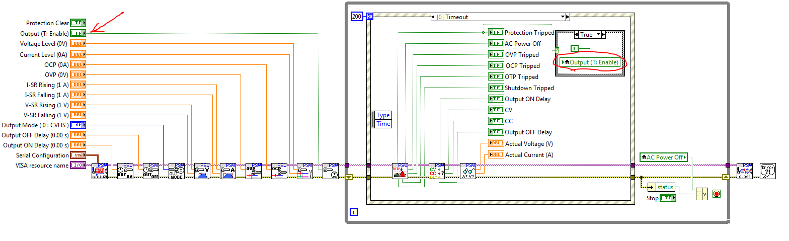
The problem I have is the boolian called variable "Output (T:Enable)" which is located in the .VI power supply example is a Panel button, but it is called several times as a local variable.
(once again, I did not write this part and please no lectures on why you should never use a local variable...)
When you change the State of the button "Output (T:Enable)" Panel, the power supply turns on and off as it should.
The problem comes when I try to control this value boolian using my timer VI. I've tried several things, and using debug, I can't 'Output (T:Enable)"to change state.
The value will change ONLY if the button is pressed or not.
ATTENTION: The illustrated local variable condition is also a security in case of short or overload, power off if the name cannot be changed.
Is there a way I can trigger "Output (T:Enable)" using 'My exit timer' but always make sure that stop you it if there is a short circuit?
This left me speechless... I tried several different things and just can not understand. Any help would be appreciated.
Thank you!
The guy
Hello guy!
You are not sure, I understand the problem in its full extent, but I'm guessing that you want to trigger the event that controls the output (T: Enable)? If you want to programmatically, create a node of the control property and use the property "value (follow the signs). Writing of a local variable will not draw the event, although this will change the value of the façade.
-
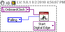
How to generate a digital signal on a negative slope of the clock?
Hello
I need to get out a finished length of the Digital pulse which will begin on request to the negative of the clock slope import (or export).
I try to get the clock, exported or imported, but in any case, I can trigger output signal on the negative slope.
What is the trick?
Thank you
Pawel
What camera you use to build your digital signal. What is the source of the clock? You can attach your vi? Normally, there is a function of data acquisition for configure the trigger where you choose the source of the trigger and the trigger slope (rising or falling), should be declining to a negative slope.
-
HP LaserJet 3800 DTN optional tray 3 will not open (but empty)
I have the optional tray 3 for a HP 3800 DTN laserject
3 tray does not open.
I have removed the printer and cannot open it.
It appears that on the left side has some kind of catch which will not be shared. I say this as wel I try to open the drawer, it tilts to the left (the right tries to get out but the left side crashes upward).
Please notify.
I solved the problem myself.
There are 4 feet at the bottom of the tray 3 optional. The 2 to the front of the unit have screws. I removed the screws and waved the units of feet that double as guides of drawer slide. Once both have been removed, the sliding drawer.
The problem was spring loaded pressure feeder had been stuck in a State more compressed inside the drawer box. The guides of slide based feet have a trigger output on them which frees pressure loaded spring trough when the drawer is pushed into the tray of the firm. The spring loaded drawer charger never push completely compressed while the inside of the cabinet drawer, and outside the cash drawer. If the spring supply pressure responsible is locked in it more compressed position inside the cabinet drawer it cannot slide past the release trigger wihtout withdrawal based foot feet.
-
That is my question.
My project is to use a cRIO-9073 there are three modules of analog inputs. Two modules of outputs analog and a relay output module. All are running in Scan Mode.
Currently I have the chassis with modules installed on my desktop. But I am not connected to any IO of the real world.
I did some initial testing with the host country and target and I'm now create IO Alias Variables I will use in my code. However, I am a little unsure about the types of variables that I should use for this project. IO Alias Variables do not have the possibility of FIFO or any buffering that I can see. But I don't know if I need that or not.
The project will be some oversight and checks carried out on the target of RT. A couple of analog inputs will be defined to trigger outputs digital if they exceed a set value.
The host will record all entries of a database and keep a circular buffer of the data in memory for display on a graph "on-line". There are also a few manual controls and access to the setpoint using the target RT.
It is a slow process. The faster the data will be recorded is once per second, and nothing does no react faster than that.
So far, it seems very easy for me to use my IO Alias Variables on my target or my host. I think that the things speed will be operational, this method would be more than sufficient. However, we have a very short development envisaged for this project cycle and I really want to avoid potential problems.
Anyone with some experience can tell me why this method may or may not have problems?
Muchly appreciated.

Patrick,
If the sampling of your application rates as you said in your post, there is really no necessary mode FPGA. Scan mode should be more than enough to get you all the data. Don't forget, you can go up to about 1 Khz using the scan mode (given that your modules are capable of these rates). Also, using scan mode I/O variables is by far the easiest way to overcome your data to the host. In fact, you drag and drop variables of e/s, corresponding to the physical channels of your modules directly in your host VI PC. Overall, I don't see any problems with your design until now, but at the same time, you did not say too much about the requirements of the project.
If you are looking for more information about cRIO Mode Scan, I suggest the following:
Using NI CompactRIO Scan Mode with the NI LabVIEW software
The Interface of RIO scanning under the hood
See you soon,.
Maybe you are looking for
-
can't connect to MSN premiun with quest
I've been waiting with msn sales and support 1-866-205-6768. I have quest and want sign up for MSN premium. I can't sign in to MSN - say account is no longer available. But said registration extended til 7/15. It is poor.
-
I have a job with 20 steps. This error occurs for any stage of perticular. It produces randomally at any stage. "The return value is unknown. The process exit code was 128. The step failed. »
-
Compaq dv6000 - screen divided into 4
Compaq DV6000 with processor intel core duo and 950 GMA intel card, whenever I start the computer, as soon as it starts, the screen is divided into 4 identical screens, and remains in the same way even after check-in. on vista home premium, looked at
-
Has been affected by a virus "Antivirus XP 2010" that has created multiple questions. I was able to fix/repair most, but this one; When I try to start in safe mode, I get the blue screen message A problem has been detected and windows has shut down t
-
Wount Windows Update, I get that 80244004 error code
What is windows update error code 80244004? Tryied updating, but he wouldn't, and I got this message.