TTL meter
I have a program of 13 dasylab which is taken from measures and sending signals TTL using a MC1208FS to a servo-motor
who performs an operation in advance or reverses jog based on data. The actuators are 11 steps in front of the sensors to measure in this application and
I would like to install a counter where, once the servo is triggered, it starts a counter which counts 11 cycles before allowing the next adjustment servo occure.
In dasylab 13 what options would be the best to perform this task. ?
Thank you Kent.
Here is a sample of litle on how to use the combitation
Tags: NI Products
Similar Questions
-
Hello
I would like to know if there is any couters who can count CMOS output pulse.
The coast of CMOS pulse are:
Pulse output: 5 v CMOS
Output pulse width: 10 ns
(It is actually the output of the unit of counting photons Hamamatsu C9744)
I have some cards PCI (6014 and 6110), but their logic of meter is not TTL, CMOS.
When the CMOS output is connected to a meter of these cards, the number of meter
has increased, but it may not be a correct counting.
If you have a good idea to count with the products OR, please let me know.
Thank you for your time and your help.
Hiro
Hey, Hiro,.
The essential is that a TTL meter will be able to read the introduction of CMOS, but not the reverse. Therefore, you are OK. This is mentioned in the last line of this link: http://digital.ni.com/public.nsf/allkb/5AB6172CAE2BEF3E8625629800597B3F?OpenDocument
An explanation of the thresholds of tension associated with each level in the chart in this link:http://www.interfacebus.com/voltage_threshold.html
The counters on your devices covered by standards TTL/CMOS, who can count a pulse input CMOS. Some general information on each standard can be found at this link: http://digital.ni.com/public.nsf/allkb/2D038D3AE1C35011862565A8005C5C63?OpenDocument
Kind regards
Jeff L.
-
Generation of signals (c) FIFO PXI-6225
Hello.
My user requests an upgrade a system existing.
I'm an analog input I need to convert to a digital waveform. As the analog input varies, I need to be able to vary the frequency of the digital wave to match. Just recently, I discovered that I should probably use a line in Port 0 on my PXI-6225. I tried using digital model Generator.VI and writes the result to a Write.VI DAQmx. I wish that some checks before I'll and rewire my material that I'm on the right track.
Thanx.
Hi Bill,
So it seems that you need to output a pulse train that changes frequency proportional to the voltage of your analog input (or proportional to an input of pulse train). If this is the case then the best way to do it is actually NOT with correlated digital i/o but rather with one edge counters. He would use the PFI lines rather than port 0.
I would like to start by this example that shows how to change the frequency of an output of TTL meter on the fly:
Output frequency of meter to change on the fly
You can read your task of entry in the same line as the generation (or you can try instead an architecture of producer/consumer ). I hope this helps, let me know if you have any questions!
Best regards
-
several finite pulse trains of TTL
Dear members of the forum OR,.
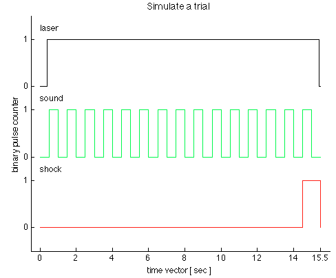
We have just received a chassis NI SMU-1073 with an SMU-6361 OR switched in PXI1Slot2 and a shielded connector BNC-2111. Aims to generate trains of three TTL pulses to control a laser, sound and shock via Matlab Application. I use the C OR-DAQmx API with Matlab MEX to integrate C in Matlab code.
I came up with the following code in the examples in C to generate a pulse over TTL time-based train:
initialDelay float64;
float64 lowTime;
float64 highTime;
uInt64 periodsPerTrain;
float64 taskMaxTime = (lowTime + highTime) * periodsPerTrain + 2 * initialDelay;Configure Pulse
DAQmxErrChk (DAQmxCreateTask ("", & taskHandle));
DAQmxErrChk (DAQmxCreateCOPulseChanTime (taskHandle, "PXI1Slot2/ctr0","", DAQmx_Val_Seconds, DAQmx_Val_Low, initialDelay, lowTime, highTime));Configure the Pulse Train
DAQmxErrChk (DAQmxCfgImplicitTiming (taskHandle, DAQmx_Val_FiniteSamps, periodsPerTrain));Departure Train
DAQmxErrChk (DAQmxStartTask (taskHandle));Wait for execution
DAQmxErrChk (DAQmxWaitUntilTaskDone (taskHandle, taskMaxTime));Clean
DAQmxStopTask (taskHandle);
DAQmxClearTask (taskHandle);I'm stuck with two problems:
1.) SMU-6361 has 4 meter signals ctr0-3. With the above code, I can generate separate tasks for each TTL signal and evoke them consecutively with DAQmxStartTask. But in this case, I guess that the tasks are not synchronized. Can I use the clock signal to synchronize the other 3, for the tasks of each is triggered at the same time? What will be the right way to do this with the C API? The step of the smallest of the discrete-time in the example is 500ms. see the picture as an attachment to check how the TTL signals should look like.
(2.) what is my physical connector on the BNC2111 to outsource these signals.
/ PXI1Slot2 / ctr0-> PFI12/P2.4
/ PXI1Slot2 / ctr1-> PFI13/P1.0
But what ctr2 and ctr3? How can I configure the physical connector outsource? Is there a function to specify that?
Thank you in advance for any advice, suggestions and directions!
see you soon,
go9kata
Hello go9kata,
for your second question, with the BNC-2111. You can route the signal from the counter for
lines PFI avialable on the block of connection BNC 2111 with the following syntax
DAQmxErrChk (DAQmxSetCOPulseTerm(taskHandle,"/Dev1/PFI0"));
I hope that helps, if not please let me know.
-
Hello
I'm reading pulses TTL of a generator of service using a meter. I apply a 1 kHz signal to the meter. Each time counter reads the pulses correctly in the first cycle of measure, but it lacks some counts in all subsequent cycles.
I use NEITHER 9181 cDAQ chassis and NI 9402 module with 2014 LabVIEW and NI Max 14.0.
My computer has the Windows 8.1 operating system.
Please find the VI joint and the front image after EXECUTION.
I also used the same VI with chassis USB cDAQ-9171 . Results have been improved, but the same problem persists.
What could be the reason for this, please guide.
Thank you!
B. Sharma
1. the loop time is defined by software and therefore won't be compatible.
2. you restart the meter patch between each iteration of loop - so that the task is restarted, it does not take samples. The new start is faster on the USB device from the device ethernet due to the latency of the lower bus, so that explains why the behavior is improved on the 9171 compared to the 9181.
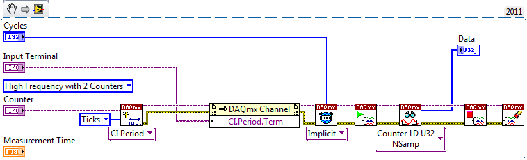
Using method 2 meter would be a clever way (maybe too smart...) to implement which, according to me, you are looking:
This will configure a second counter (ctr0 is paired with ctr1, ctr2 is paried with ctr3) to generate a signal of a period known (time measurement). The meter is taken into account the number of external pulses during this period, and since we are because data in terms of 'Ticks', it will give you the number that occurred during the measurement time. This measure is repeated for the specified number of Cycles without software-timing or latency between cycles.
The appeal of reading will have a time-out value long enough to ensure that all cycles have completed (or you can query to see if the task is made first of all to give the user the option to cancel the measure).
Best regards
-
How can I use two counters to capture a pulse ttl for a specified time
Configuration: Card counting 6062 PCI w / BNC 2121 Board running under LV 9.0 PerkinElmer Avanlance Photodiode (SPCM-AQRH-13)
I searched through the forums and fell on the theme of framing an image while collecting signals from a source for a specified time.
The example in terms of falkpl in 2005:
"
Dismal Hello,
I'll try to point you in the right
direction to start coding the application, but do not forget my
suggestions have to be modified to your specific request.For
the task output redeclenchables finished meter you need to
your counter seconds in this application, I suggest to take a look
in the Finder example in LabVIEW ('Help' are examples) and less
DAQmx hardware entry & exit"" generating digital impulses. Here,
you will find some Gen dig Pulse - Retriggerable.vi. You can use this for
Create your door 4 pulses ms it's over (not a pulse train) and
redeclenchables (for each time you go to the next step.In
regards to the configuration of the first counter, there are several things to
consider, and I can offer initial help to get set up. You
in-house allows to route internal CTR1 (4ms of pulse) output for your CTR0
Door to measure only during the time. Here are additional
Info to do this in LabVIEW. The source of your task of edges ABOVE County
will be the TTL signal you are measuring and counting. It comes
on the PFI line that corresponds with CTR0 Source.When
you make a measurement finished with CTR0, you will take only heads while
the door is high and your source has a rising edge. You can set the
measure over to start on a trigger, which is not clear in this
for example, that you have identified. Since you know that you have a finished 4ms pulse
time to measure, you can set the duration of your measure
as a result.I found this
Forum which may help some, but the coding is
textual. I hope this can give you a good starting point for
programming. -
OR USB-6211 is used to count climbing on board TTL
Hello
I'm new to NOR-DAQ cards, and so before buying whatever it is would like to know if it is possible to use a device, NI USB-6211
County and bin amounting to edges of a TTL signal.
What I want to do is to count how many rising edges of a TTL signal I get in a period of 1 ms; a 20 Mhz sampling frequency should be fine.
I would like to use Matlab to control and read the number of edges that are counted as well as in the meantime write and read digital IO ports from the USB-6211.
Is it maybe possible to leave the external TTL signal trigger a 6211 counters, an output then periodically (1 ms) and reset the value of the counter?
Is it possible and if yes, is it a good idea?
Thanks and regards,
Manual
Manual Hi
In order to generate this signal, I could use a second timer mode continuous pulse Train generation, right?
-> Right. You can choose between 2 options
(1) get the signal to another device, for example signal generator or something like that. If you cannot use such a device, you must select the second solution->
(2) generate the 1ms period square wave with the meter of the USB-6211 seconds
I don't know a smart way to generate the 1ms period signal without the software side. You need the software to configure the second counter, route the signal to the second counter for the first counter and so on.
Maybe you can use what is called "panel test" inside the Explorer Measurment & Automation to generate signal. The Measurment & Automation Explorer is a tool provided with the driver for the DAQ cards. The original purpose of this software utility is to configure your hardware, test and so on.
I don't know if it works, but I imagine that the following solution:
You use the test panel called inside the Measurment & Automation Explorer to generate the 1ms period signal (see attached screenshot and http://www.ni.com/white-paper/4638/en). You have no additional program to run the test Panel. Box USB-6211, you use a wire to connect the signal output of the meter of second at the entrance to the first counter. After that, you run Control Panel to test the generation of signals for the seconds counter. At the same time, you start your Matlab program and configure only the first counter. You will need to run the Testpanel all the time if you want to run your measurment.
Not very nice, but maybe the only solution.
Best regards, Stephan
-
Problem with signals TTL metering: confused with counting
Hello
I use a TTL of 0.2 Hz signal to synchronize two devices. I use a Usb-6210 card to count the pulses TTL. The meter goes off when it detects the edges increase. In my case, the meter was sometimes triggered at low altitude, which causes wrong results (see attached pictures, the TTL signal is sampled at 20 Hz and the dots represent an increment of the counter). How can I solve this problem?
In addition, the cable that connects the TTL output was welded by myself, would that be a problem of bad contact?
Thank you very much
K-X
What is the nature of the device producing the TTL trigger signal? Is it possible, for example, that it could produce a 1 microsecond pulse (which might not be visible on your signal ground) that would trigger the meter? You really produce a digital pulse (i.e. your something circuit which is 'on' or 'off' as opposed to 'product analog voltage in the range of 0 to 5 volts')? Are there any other devices around that could produce the impulses that are "picked up" by your meter? The cable connecting the TTL is armored pulse for the meter? The shield is based at one end?
These questions (and the previous) suggest that the problem may be 'electronic' rather than 'LabVIEW '...
-
measurement of input frequency TTL with sheet metal entered on a device USB 6363
Hi all
Is there a simple LabView vi to measure the frequency of entry TTL cable for the entrance/s, four counters available on a device USB 6363? I have LabView 2014 FDS installed. I guess using 2 4 meters would be better than 1 for 32-bit resolution, correct?
Thank you
John
Hi jac2015,
There is an example of a measure of frequency located in LabVIEW help-> find examples-> material-> DAQmx entry and exit-> entrance of counter-> meter - reading pulse width and frequency (continuous) .vi
Take a look at it and see if that helps. There is also a very useful white paper on considerations to make when measuring frequency, you can find here:
«Measures of frequency: practical Guide»
http://www.NI.com/Tutorial/7111/en/
The main considerations is how often should the signal you want to measure?
I hope this helps!
-
Sampling rate higher for the measurement of precision meter
I have a BNC 6259 M Series DAQ USB. I am currently using the DAQ Assistant to perform simple cash rising measured with the measuring mode single sample on request. I tested my VI with a known square wave with a function generator signal and it clearly lacks a few edges. I think that the solution lies in faster sampling. However, I was not able to understand how to use clocks to set up continuous sampling mode. I tried the forums and I found articles that were close, but not quite exactly the problem I am facing with as (http://forums.ni.com/t5/Digital-I-O/trying-to-use-NI-6251-s-DIO-port-as-input-and-output/m-p/448035#...) or (http://forums.ni.com/t5/Multifunction-DAQ/Using-Counter-of-PCI-6024E-with-Quadrature-Encoder/m-p/984...). Any guidance here would be great.
In fact, the calendar should not have anything to do with the edges being detected. Configuration of a sample clock for a county of just edge task allows you to enjoy deterministically in the account register and has no impact on the edges which can be counted. Also, the analog examples really have nothing to do with what you seem to be asking questions on.
... So it leaves the question unanswered as to why you might miss the edges. Perhaps the following information could shed some light on the question:
1. it is possible that you do not configure the counter exactly as you think you are. Can you post the VI you use? As a point of reference, count digital events shipping example does not use any clock sample timing and just questioned the value of the register count with a software loop, but the meter should not miss all this edge on the input source. There are examples that are timed by the material available as well, but this is not necessary, unless you need a constant specified dt between your counter samples. To use the examples of the timed sample, you will need to generate a clock of either another subsystem on the map or use an external clock.
2. assuming that the configuration of the counter is not the issue, there may be a problem with the method that you use to determine if you are away from the edges. How do you know that you are away from the edges? The function generator produces only a finite pulse amount? You start the meter before start out impulses?
3. If the two points above do not raise red flags, it seems likely that the meter is registered just not some of the impulses of your FGEN. Can I assume that the output of the FGEN is 0 - 5V TTL? What is its frequency and duty cycle? The maximum external source for the meter on the M-series products: DAQ (like the 6259) is specced at 20 MHz, but this depends on a clean signal with good connections. At frequencies above it, the bandwidth of the front-end of the PFI lines becomes limiting. If you have an available specification document for your FGEN I'd like to be able to see it.
I hope this gets you throw on the right track to solve the problem - impatience comes back with more information.
Best regards
-
Count the edges of the 2 signals TTL (Heidenhain linear scale)
Hi all
This is my first post here. :-)
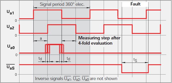
Currently, I'm doing a VI to be used with a linear scale. The linear scale gives 2 TTL signals that have an offset of 90 °. The change in distance of the linear scale is given by counting the fronts and edges of the two signals. See the following image: Ua1 is signal 1 and signal 2 Ua2. You can ignore the other signals.
Now, I want to count the 4 edges in order to translate the 2 signals in the distance. This means that I need advanced two counters for Rising-rising, Rising-Falling Falling Falling, falling on the rise for 2 signals. I tried to do 4 points two counters in LabVIEW but that of course does not work, because an acquisition of data can access the card TTL or I did it wrong.
Once I have to handle this, I also want to understand the meaning.
My card TTL: NI 9402
My electronic Heidenhain interface: 100 IBV (http://www.heidenhain.com/fileadmin/pdb/media/img/598_160-23.pdf - also at the origin of the image)
Hardware configuration: linear scale-> IBV (Elektronic Interface)-> NI 9402-> LabVIEW
Signals: Analog 3-> 3 TTL-> OR 9402
I hope I do not double post. Any help would be greatly appreciated.
I used Heidenhain linear scales in many applications.
As stated in the previous post, the output of your balance is as a quadrature encoder. Therefore, you must use an entry of the DAQ card counter to measure the position of the scale.
The desired X 4 mode is done by the meter itself (not possible with some old maps of OR).
As starting point, see measure angular Position.vi that comes with examples of LabVIEW. On your linear scale, change the type of the polymorphic DAQmx create channel VI CI linear encoder and etiquette of pulses per revolution at a Distance by pulse.
Feel free to post back if you need further assistance.
-
Why do I get signals ghosts with the meter?
Hi, I am able period using the NI 9401 on a cDAQ9174 chassis. I have a sensor whose output is 50mV LO and HI 4500mV, and this is easily measured with a scope and a DMM. Furthermore, the scope shows very clean transition, no noise near the 2, 5V TTL threshold. The probe monitors pattern reflecting on a spinning wheel. Measures the time of the order of less than 0.3 seconds, but, curiously, the measurement period seems to be good for a few cycles, and then suddenly these values close to ZERO are observed. (Excel data show these values literally '0'.) What is c? Where are these unwanted readings from?
Also, see the code that I use to record data from the period, and a typical example of the data plotted in Excel. One thing I'm confused about is the timer in the WHILE loop. How the meter may return a value that is smaller than the function parameter WAITING in the WHILE loop? The WAIT function is set to 100ms, but the meter will return to values far less than 50ms.
Is there a way to remove these values in the software? For example, can I just throw any value less than 0.050 seconds? This kind of fix would be perfect for our application; It's a little gross, but she would get me to the next step in our project.
I really appreciate your comments! This photointerrupter is supposed to have the advantage of being a camera and free of noise in the environment, up to now, the only noise in our environment is the small DC motor spin our wheel on our lab bench... not a harsh environment at all.
Dave
Hi Dave,.
That's what I think is happening here. In the configuration of the measurement of a meter task period DAQmx, the source of the signal is connected to the door of the meter and the internal time base is used as a source. When the input signal is HI at the entrance to the Terminal, a count is saved for each rising edge of the timbase to the source of the Terminal. When the signal of door to LO County is drawn from the register in the buffer and legumes subsequent source are ignored until the door is HI again.
Now assume that the signal of your door is swinging very quickly prior to staying at the State HI or LO. Whenever a HI LO oscillation occurred, a count would be drawn from the register of the meter. If this rise and fall of the door happened quickly enough, it is quite possible that very few or none of the timebase impulses were actually counted to the source terminal, thus recording a very low double value in a buffer of the computer. When these sets of values has been extracted from the buffer and written into the worksheet, accuracy of scripture to the worksheet VI may have been set to the default 3 decimal, so write "0" s to the file.
The speed of the swing may be the order of 10 to 100 ns, fast enough at your fingertips, do not register. The quote that I copied the help file describes the behavior with the digital filter enabled. When you apply the digital filter, a county is not from the register unless the signal of the door remains HI for a fixed minimum amount of time. With the filter, the period 0 counts are not sent to the buffer because the door is not HI for the minimum period of time.
Brian
-
Hi everyone, I'm trying to accomplish something that seems simple to me, but I'm having a hard time to implement.
What I have is two impulses. The first impulse triggers off a signal external TTL at 10 Hz with a 3ms delay, so it also fires at a frequency of 10 Hz. The second impulse triggers off the coast of the first impulse with a delay of 100 microseconds, but I need this impulse to fire at 1 Hz instead of 10. This seems to be a classic example of triggering, but I have a problem with LabVIEW. (Note: the 2nd pulse triggers the first pulse instead of the external trigger for the stability of synchronization.)
What I need is very similar to the example shown here: http://digital.ni.com/public.nsf/allkb/204538A044431C9B86257377004EB952, as in, I would like to break my fast signal using a small moment of a slow. Except that in my case, my fast meter (10 Hz) is triggered and the slower meter (1 Hz) can be arbitrary, rather than the reverse as in the example.
I tried to do by using the three counters. One of them is a redeclenchables impulse that controls the 1st impulse (ctr0). Another is the same thing, but used for the 2nd pulse (ctr1). And the third uses just the implicit/ongoing synchronization tool to create a 1 Hz signal (ctr2). I then tried to put in the 'break' property node in ctr1 use the output from ctr2 as source to pause, but it has erased my 2nd pulse.
I'll upload a VI as soon as possible (maybe it is a negligible error), but this sounds like a correct approach?
Thank you very much!
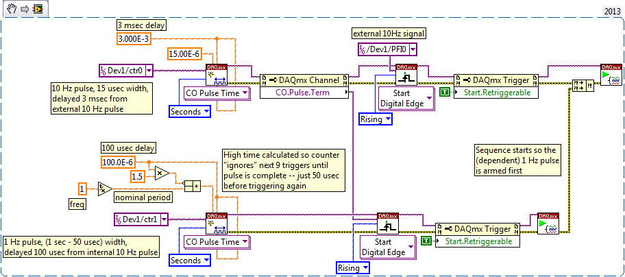
The code snippet below is a starting point to generate your 2 impulses with only 2 counters. No need for a 3rd counter or type of relaxing break.
Hypothesis: I treat only the rising/tip of impulses as critical timing functionality, making sure that the edges the timetable you have described.
Both are just redeclenchables single pulse, one triggers the external signal of 10 Hz with a delay of 3 ms. The pulse is short enough so that the meter will be easily ready to retrigger 100 milliseconds later.
The second counter triggers the release of the first with a delay of 100 usec. This time the pulse is set to be long enough that the pulse will not end, for about a second. It ends just in time for redeclenchee by the 10th later trigger edge. If these impulses will be at 1 Hz, with edges of attack delayed by usec 100 to another counter msec and 3.1 of the external pulse source.
-Kevin P
-
DAQmx generating triggers TTL and triggered read it
I am running LabVIEW 2013 on a Windows 7 PC and I use a card PCI-6251 DAQ with a BNC-2110.
For my application, I need to generate triggers TTL (for example, with a frequency of 1 Hz). At the same time, I need to run data to HAVE which is triggered by the same TTL signal.
So far I managed to implement the TTL square signal properly with a spot of meter output - I can see the triggers on a scope. I also have a task of entry of HAVE and included a digital triggering. He works in part, and I have a few questions:
- The physical channel of triggering TTL is set to ctr0. This seems to be associated with the PFI12. I rather would specify the terminals directly in my program - is it possible? The ctr0 is not labeled directly on the BNC-2110.
- The task of IT is triggered by the PFI0. I connect a cable from PFI12 to PFI0. Is this really necessary? The task of the AI can be triggered internally for the same counter? My external hardware must be triggered with the same signal as the acquisition. So far, my solution seems to be the only way I can make it work.
- Digital triggering for the task to HAVE it is configured to 'rising edge' trigger. However, when I run the task to HAVE it continuously in a loop, it seems that it is triggered Alternatively edge bearish and bullish. I checked this by connecting the meter to exit on PFI12 directly to the input string for the task to HAVE it, and I observe that the periodic square wave changes sign. Why is this? It is a problem for my application - I need to be able to always trigger on this same Board.
Thank you very much for your help.
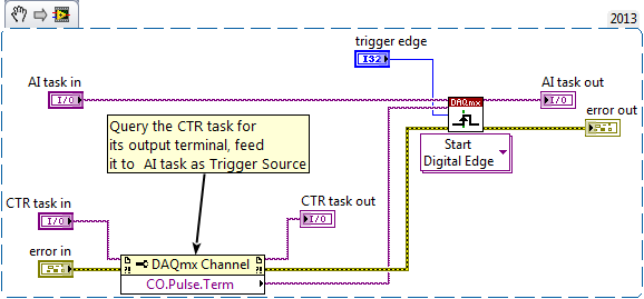
hmalissa:
You can query programmatically for the pulse of a task of the meter output terminal using a property DAQmx channel node. Here is an excerpt. Just save the image and drag the file into a LabVIEW block diagrom and turns it into code. You do not have to use this as a Subvi, controls & indicators are just there to identify the task who is who.
Bob: interesting experience. But to help future readers to draw the erroneous conclusion, I just would insist that a timed hardware task still * fact * produce much more repeatable calendar timed sample a software task programmed in a software loop. Example of Bob is not address the regularity of the individual sample interval, just by comparing the driver DAQmx or MS Windows timer is more sensitive (and repeatable) to marking the end of an interval of 1000 msec.
-Kevin P
-
DIO using loop to generate TTL
Hello
I have a sbRio and on the FPGA, I have a loop that runs every 5 US. The loop has a counter that increments with each iteration, and I acquire analog data each cycle (effectively setting the rate to 200kS/s). The counter is used to generate a Boolean value True or False. Thus, for example, if the count is less than 200 (for example) the value is False, but greater than 200, it's true. The counter then resets back to zero in, say, 400. This counter is used for two purposes - the resulting value of T/F is sent to a DIO port then it becomes, in effect, a TTL output, and because I store the meter with the analog data, it acts as a reference for where the data were sampled in the cycle TTL.
My problem is that when I look at the output "TTL" on an oscilloscope everything seems pretty OK... except that now and then I get a glitch where it suddenly either falls to zero or "stutters".
The question I have is this - if I write a True value for a port DIO in a timed, loop makes this "lock" of value until it is changed or does literally flick on then turned off during a period of time (the implication being that it is actually not a true continuous, but a series of true/false steps which occur on a timescale much shorter than my loop time)? If so, is there a way to make sure the value remains constant until the next iteration of the loop? If this isn't the case, then should I move using ticks rather than at the loop timer?
Thanks (and sorry for the length).
I think the question is read the values half/full cycle. If I replace those with constants, the problem seems to disappear. I moved the reading of those outside the main loop, and that seems to have worked.
Thanks for your help! The loop of the case has been deleted since, as you pointed out, it was not necessary. Oh and sorry for the twisted...
Maybe you are looking for
-
Hello world I face a problem, whenever I create an album with radio stations, my iTunes just takes a random file as cover photo. How to solve this problem?
-
Available to the pins of the webcam module
I'm building a detector simple alpha particle and want to use this webcam that I'm waiting to receive. So I hope someone can help me understand what the pins are on the webcam module. As the picture below shows the number of spare parts is 626656-001
-
Call the allocation of memory function of library
Hello I want to call a dll of LabVIEW and one of the entries expects a pointer to double (double *). I did things like that before and use create table to allocate memory in LabVIEW to pass to the dll. This time what is expected is a pointer to a uni
-
backup of several computers with windows 7
If I backup multiple computers to a single drive external HARD, with the backup of windows 7, I'll be accidental image or are they separated? My concern is that each computer will replace the previously backed up computer and everything I have it is
-
FIX: Cannot change font size WinMail/WLMail with installed IE9 [FYI]
You can't change the font size in Windows Live Mail or Windows Mail after installing Internet Explorer 9http://support.Microsoft.com/kb/2601253 The fix above is included when you install... MS11-081: for Internet Explorer Cumulative security update: