USB-6343
The laptop does not recognize a new device when I plug the USB-6343 in the USB port. He used to work, but then has been intermittent, acknowledging only from time to time, but now it doesn't work at all. Any ideas what could be the problem?
It ends up being an intermittent USB-6343. Slightly pressing the instrument would be to appear on the bus.
Tags: NI Hardware
Similar Questions
-
synchronize the outputs digital AND digital NI USB 6343 entry
Hello
I use NI USB 6343 to fly 1 TTL devices. This device can also produce a TTL signal to indicate if the door is opened/closed.
I use digital Bool 1 line 1 Point. I was able to reverse the opening/closing of the door on time. But I would like to synchronize the DI and DO it right.
I tried to throw in the clock aboard, but he failed.
Is it possible to synchronize the DI and DOI onbaord/hardware clock?
Any idea will be great!
Thank you!!
Hello
Synchronization of your tasks of DI and shouldn't be possible with your device. You'll need them timeless has a clock that is usable by both. This information is available in the X series user manual
http://www.NI.com/PDF/manuals/370784f.PDF
PG 6-9 and 6-13You can also find information and examples of synchronization of the various tasks in the article below.
http://www.NI.com/product-documentation/4322/en/Good luck
Eric
-
Sample USB - 6343 Counter clock
I use a USB-6343 CTR0 to measure the angular position. I expect to ~ 1 million encoder pulses (or account) per second. What USB-6343 clock signal would be preferable to use the counter sample clock?
Dar Hi,.
At what resolution do you need measure the angle?
One of my colleagues has compared the maximum sampling frequency on the counters of series X USB to be approximately 8 MHz for a single channel, continuous operation for 10 minutes. However, if the signal that you intend only generates pulses at 1 MHz, 8 MHz rate seems unnecessary because you will receive the same reading several times.
Concerning the two methods you mentioned, either would not be possible:
(1) you could count the external signal and sample at regular intervals. For example, if 10 kHz sampling you'd expect to see ~ 100 strokes per sample if clock signal is 1 MHz.
(2) you can also use the meter to count a time base internally (for example 100 MHz) and the sample out of your external signal. Thus, during a period of your external signal, you expect to see 100 graduations of the time base.
It seems that what you're trying to do is to measure the frequency of your encoder at regular intervals. To do this, I suggest you actually a variant 3. X series cards support a measure of frequency clocked for example (see the X Series user manual). The card has two occurrences of the external signal as well as occurrences of the internal time base known and uses it to determine the frequency. The one caveat is that the signal you are measuring the encoder must be at least two times faster than the sample clock signal. I suggest to use Freq Out or another counter to generate the sample clock.
Best regards
-
Measurement of temperature using NI USB-6343
Hi all
Someone at - he temperature ever measured using an NI USB-6343 or something close to it? Encountered problems?
I was reading on the device and it has been suggested that the conditioning of signals may not be required, and I'm a little worried...
Normally I use a DAQ Agilent but this specific project, I'm working on that will require a unique moment and USB-6343 handles a majority of my problems along will be many examples of coding.
-scrider
Scrider,
You want a device that has USB connectivity like the 6343? If so, we have several hardware based USB DAQ for thermocouples. The links below will show 3 devices, we have:
http://sine.NI.com/NIPs/CDs/view/p/lang/en/NID/208177
http://sine.NI.com/NIPs/CDs/view/p/lang/en/NID/201881
http://sine.NI.com/NIPs/CDs/view/p/lang/en/NID/207471
Now, I know that some of them will probably not ideal for your app, but I wanted to just give you options. It also depends on how fast you want your sample rate is. These devices are specific for the use of thermocouple, but you can still use them (excluding the tc01s) for voltage readings. I hope this helps!
-
NEITHER USB-6343: erratic low frequency 1 counter measures
Dear members,
I'm looking for help with a measure of low frequency counter. I tried to make it work for a week or two, but I keep getting erratic measures. It will read the rpm properly for a second or two and then it will give a ridiculous value on the order of 10,000 times the correct value. I can not get a constant value.
I use a DAQ series X NI USB-6343 multifunction with Geartooth Honeywell GTN1A111 sensor. I enclose a sketch of the wiring configuration. I think that it is correct. Sensor output to the door of the meter.
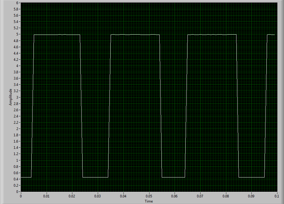
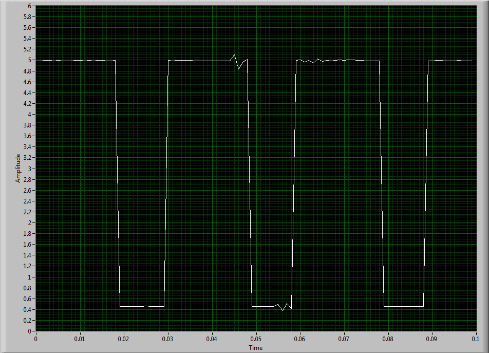
To try to solve this problem, I hooked the sensor to an analog input channel to make sure that I was getting a TTL signal by sensor. I noticed every once in a while I'd see a glitch of little noise in the signal and I guess that's what is causing my problem with the meter. I inserted two waveforms of the sensor signal (one with the clean signal) and the other with the glitch of noise. My understanding of a TTL signal meter channel will examine LO voltage when it is below 0.8V and HI when it is larger than 3.8V. So I really do not understand why these little glitches could be the cause of the problem because they are well below and above 0.8V and 3.8V, respectively. I think that the noise comes from a frequency converter used to drive the engine. I tried the system as much as possible of the Earth.
I guess I'm looking for another approach. I could potentially use a digital filter to help with noise? The glitch is in fact the problem or I forgot something. The VI in question is attached.
Thanks in advance,
Mike
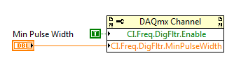
Have you tried to set up a digital filter yet? Obviously the seeds are collected as an additional transition (the method of low frequency counter 1 measure the period and then reverse, so a short glitch would record as a very high frequency).
You can enable the digital filter with the following property node:
Min pulse width is guaranteed pulse past the filter, so it should be low enough for the real signal is guaranteed to pass through (but high enough so that the glitch is always rejected).
Best regards
-
How to synchronize clocks on USB-6009 and USB-6343
Hello
Can anyone provide an example on how to synchronize clocks on USB-6009 and USB 6343?
I checked the example screws, but it shows that we must use 2 counters, one as the clock of the source and the other as a trigger. But only 1 CLK 6009.
I read the user manual and it is mentioned to use (AI/start-trigger) in order to use PFI0 as source.i am somehow confused about how to achieve this.
Furthermore, what would be the physical connections?
Thank you
LV_Enthu
Unfortunately, you won't be able to completely synchronize your devices USB-6009 and USB-6343. As you have seen, the 6009 has only a meter on board.
You can certainly use PFI0 as an input to start your tasks at the same time digital release. However, the 6009 is a strictly timed by the software. There is no way to import an external sample clock.
-
Simple examples of analog output USB-6343
I've tried passing by 'find' examples and does not know how to find what I want.
I'm doing a simple analog output on a USB-6343. Examples of waveforms say they work with the USB-6343, but I really don't want a waveform, just analog of output does not exceed 10 Hz speed of renewal. Some of the more simple examples show that they work with the pcie-6343 but do not list USB-6343.
I worked with USB-6009 in the past, but when I try to use an analog output task that uses 1 sample on request, I get the error "not buffered operations clocked by the hardware are not supported for device and channel type.» Set the size of greater than 0 buffer, do not set up the timing of the sample clock or the value Type of sample On Demand time"
I tried samples N, 100 samples to write to 10 Hz - the same error. Samples of continuous - same error. 1-sample - timed HW - same error.
There is a series of examples of I/O for the X series? Is it possible to search the device examples rather than go through all the examples and by checking the list of devices individually?
Is 'size of the buffer' the 'writing samples"in MAX?
After contacting the support I was provided with the names of the more simple examples for analog i/o:
Analog output-Gen power Update.vi
Analog Input-Acq & chart voltage-Int Clk.vi
They are found in the getting started screen of
Click 'Find examples' near the lower right corner
Filter the results to material by clicking on the menu drop down for the material in the lower left corner and selecting USB-6343 (only connected equipment will be displayed)
Don't forget to check the box "limit results to material" below.
In the center pane, double-click 'Material Input and Output'
Double-click DAQmx
Path for the analog input - double-click Acq & chart analog measures - double click on tension - tension-Int Clk.vi
Double click on analog generation - double click on Power - Gen Update.vi of analog channel output voltage
The examples are for the single data point. Samples and exit multiples are produced by putting the writing or reading VI inside a loop. The beginning and the clear functions should be out of the loop.
Additional information, I need technical support was how material-filter results and identification of more simple examples which were not obvious from the examples of names.
-
I inherited a data USB-6343 acquisition unit and tests a few pieces I designed. The latest version of the chip has 3.3V / s and it appears that the 6343 only supports digital i/o to 5V. Is there a quick way to convert the output data acquisition in 3.3V 5V? Thank you.
Hello
I thought it might be useful to display some of these to the top on the same topic:
I understand you are trying to run the code example "Static digital output with adjustable logic level. When you set the level to 3.3V logic you see an error message.
Here is an article on knowledge (KB) which explains what this message means. In this KB is now talking of another property, but the concept is still the same.
http://digital.NI.com/public.nsf/allkb/05A563FE3AA7B3C286256FF90077C303?OpenDocumentI also did a little more research and found this useful reference which caught shows supported properties for the device, and you can see that this property is not supported.
http://zone.NI.com/reference/en-XX/help/370471Y-01/cdaqmxsupp/USB-6343/In conclusion, you are limited to the 5v output only if you need to obtain 3v to drive your relay maybe I could suggest that you use a converter logic circuit that converts your 5v with 3.3V.
I hope this information helps.
Let me know how you go.
Kind regards
Kevin Ross
National Instruments
Engineering applications
www.NI.com/support -
Frequency counter measurement crashes when you're away point zero (NI USB 6343, error-200284)
Members of the Forum,
I have problems with a measure of the frequency on a DAQ Mulitfunction of NI USB 6343 X series. I use the meter 1 (door axis for frequency signal, PIN to DGND 82 77). The couple HBM T10F flange that I use (powered by a power supply of 24V) emits a signal of frequency between 5000 and 15000Hz with 10000Hz being the zero point. Couple flange has a capacity of 5kN.m (15000Hz = 5kN.m; 5000Hz = - 5kN.m).
I have been using the VI attached for a few months now without any problems. Now, the VI works fine as long as the couple remains inside a few hundred Hz of the zero point. However, when the frequency increases further reading couple begins to freeze and finally I get either of these two errors:-200279 or-200284 related samples is not not available. I noticed that the light on data acquisition close compromise during these periods of frost.
Here is an example step by step my problem using cal shunt of the flange of the couple:
1. I have run the VI and couple bed properly around 10000HZ (Active light, indicator light ON)
2. I have apply the excitation of 5V to the shunt cal and frequency climbs to about 50% of the ability to couple brackets (as it should)
3. as soon as I remove the excitement 5V playback freezes and the light on the acquisition of data.
4 if I apply the 5V once again, until the timeput occurs, the led turns on and the acquisition of data reads the signal correctly.
This type of problem would be more DAQ-related or is it the flange of the couple itself.
Thanks in advance,
Mike
Solved.
I did some troubleshooting this morning and it turns out that the vibrations of the system had not tightened a screw that was connector to the stator flange torque causing a bad electric signal of the torque flange itself.
Everything works fine again.
-MB
-
NEITHER USB-6343 analog and digital grounds
In the manual for the NI USB-6343, it is said that the mass input/output, analog and digital terrestrial are related, but by a small sign. For my application, I am attaching all 3 these grounds to exit the box (I'm tie all areas with physical threads). It is perhaps a silly question, but it's OK to do, correct?
This should be OK unless there are large currents flowing on ground conductors. If you have important currents in the ground, you have other problems that must be resolved before you connect the DAQ hardware.
Lynn
-
Error writing to usb-6343 digital output
Hello...
I have a trask to produce some digital waves... so I use usb daq-6343. to start, I am writing 1 simple value (i.e., 1) to the first pin of the port. but I get the error here, I enclose error png and part vi of the code... Please help me here...
Thanks & best regards,
-
How to generate a square wave of continuous digital output using USB 6343?
I need to generate a square of 600 kHz from my 6343 wave. The specifications indicate I could use PINS P2.0, but I get an error saying that it is not supported.
Thanks in advance for your help.
Jodi
Dan,
Thank you very much. Counter method worked very well.
Jodi
-
NEITHER USB 6343 negative DC voltage after power function generator
Hey all,.
I'm having a problem with my DAQ. I'll generate a square wave in Labview with a generator function and that the output to my DAQ. The function exited through the acquisition of data very well; However, when the production is stopped, a negative voltage remains equal to the amplitude ("drawing" below). This happens if I use the express VI DAQAssistant, or manually create the channel, generate the function and the function read/write on the channel. This tension continues even after the VI is finished running. The only way to get rid of it is physically cut the DAQ and turn it back on. Any thoughts on why this might be, or how to fix?
Start VI
____|____|____|____|____|____|
____|____|____|____|____|____| _ _ _ _ _ _ _ _ 0V
____|____|____|____|____|____|____________ - A V
____|____|____|____|____|____|
End VI
Tom
I thought about it. I had to add some more to the clock. I had added a data point in the table of waveform which was written for the acquisition of data because the timer wrote n samples, instead of n + 1

So, to recap: I pulled the table leave the waveform data, inserted a '0' at the end of the wave, reintroduced the data of Y in the form of wave and incremented to the timer of a sample (because I added a sample for waveform data).
-
No configurable USB-6343 with instrument I/O assistant
Hello everyone,
It is the first time I use a camera OR with Labview (normally using third party material), and I have parameters upward.
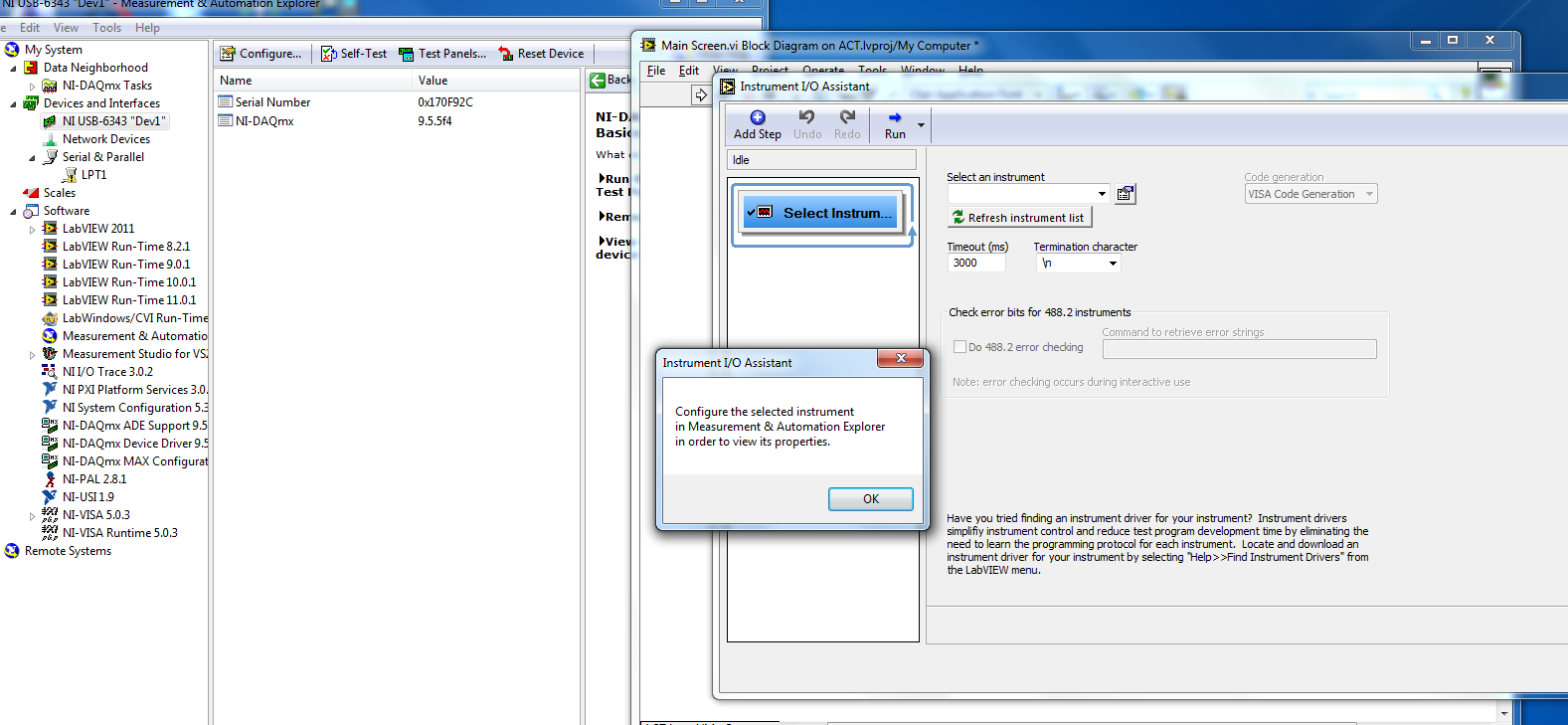
Istalls fine device driver and I he sees with the measure Automation & Explorer. What should I put in place in order to make the nodes in labview?
I always get the message that I need to set this up, first (list remains empty). What do I need to set up? I tried to add a task, but I don't see anything else.
The evil wizard. Use the DAQ Assistant.
-
Hello
I use the digital output to USB-6343.
Sometimes when I stop writing (clear the task) the rest at high output pin (I see it in the oscilloscope).
Is it possible to set that after earasing task output pin will always be low?
Thank you
Leonid
Thank you
Maybe you are looking for
-
The remote control is included in Qosmio DX730?
I have a Qosmio DX730 - Manual of the user is pointing to a media remote.What is it meant to be included? There is no reference to indicate that it is an optional element.
-
I bought MS Office Professional for download, my opus system is XP. I think that my PC cannot install this Office software because my Service Pack 2 has expired 2 years ago? Then... often I download SP3 from the Microsoft Web site or I have to b
-
Logo of Windows vista desktop on startup
How can I remove the logo of 'Windiows Vista Starter' in my office?
-
WRVS4400N does not connect to internet
At home, we have a linksys WRVS4400N router. As of recently, it does not share the internet for the rest of the network... and I don't even know if it has internet. I tried to reset the router, the modem (7 years at Wired speed of bellsouth) reset an
-
Boot CD not reconigized by operating system
What should I do to fix this