VeriStand Webcast
Hello
I tried to visit the German webcast of NI VeriStand
It works well on page 11 of the 23. Then it is not working well the speech flashes
I tried it on some other machines - still the same.
Is a webcast in English available
Jürgen
Hello
I got it running in safari webbrowser and more recent adobe flash player. #
It seems Veristand could be very interesting tool for me.
Concerning
Jürgen
Tags: NI Products
Similar Questions
-
With the help of a data base with VeriStand BOX
Hello
I use a BMS that communicate via CAN with VeriStand. I imported the database of the device with NI-XNET (with 3 nodes CAN) and I can see some parameters of acquisition under veristand correctly.
But now I want to order a State request and check if the command is well transmitted.
To do this, I sent a node and try to see the information in another node and it does not work.
So is this the proper way to check transmission CAN or is there another way?
Thank you very much

Hi Vincent,.
If I understand correctly, what you're doing are a loopback test. It is indeed a good practice for communication. Have you connected your ports CAN directly together? In some cases, depending on the hardware you are using, you may need an external power supply for the transmission CAN occur.
In all cases, you can also check your good communication using the tool called NI XNET Bus monitor.
Does that answer your question?
Good day
M junior
-
AutoStart VeriStand using LabView project
Hi all
I want to manage through selection LabView and deployment of projects on my PXI system.In order to know which project is running that only, I founded the solution to create an ad-hoc ALIAS that appears at the top of the list. Is there anyone who knows a smarter way?
Attached is my example .VI
Thank you very much for your answersYou can watch the NI VeriStand - Get function System State.vi located in the NIVS palette. Notably, she returns the path to the definition file deployed where he is already running a (and you can use Connect to System.vi to run a definition instead of a project file). It is perhaps more convenient than your alias workaround solution!
-
Custom control in the new VeriStand workspace
Anyone know if it's possible and how to make the custom to the new UI controls? I have a custom device that creates channels 400 + and I would like to find a way to add them to the user interface without having to manually configure each channel individually.
I have a way for the user to choose if each digital output is discreet, PWM or encoder mode. Currently, they have to drag into individual channels labeled 'Enable channels', 'Output Mode' and either 'Discrete Value,' 'PWM Duty Cycle' & 'Frequency PWM', or 'Encoder quarter' & 'encoder Index Control. " Is it possible to create a custom control that contains Boolean controls and digital necessary? I know that this was possible in the old VeriStand workspace, but I have not found a way to do in the new, as there does not appear to use a directory full of screws for its controls.
Thank you
Mitch
Hi Mitch,
I'm sure that this functionality does not yet exist for the Manager of the user interface, but I guess that NEITHER is likely to know that it is a widely used feature.
When I asked him about this a few months ago, I think the answer is that it must continue to use the workspace controls customized with the workspace and migrate the rest of your features to the UI handler. Once the UI handler and the Worspace may operate at the same time in the same application VeriStand.
Could you describe the feature you're looking for with screenshots?
I hope this helps, but maybe someone of NOR can enlighten us more about it!
-
Mode of scanning/FPGA for a CRIO by Veristand
Hello!
I have a small error using my CRIO 9081 use with CAN communication, here's what I did:
1. I use the CRIO with scan mode and customized it "Scan engine" and Ethercat for show my analog modules under VeriStand, it's ok
2. I use the CRIO with FPGA Scan interface (together under Labview) to detect my modules CAN, also ok
3 - then I wanted to see the CAN and analog modules, so I use this page:
http://digital.NI.com/public.nsf/allkb/0DB7FEF37C26AF85862575C400531690
And here's my problem:
with this method I am able to see the two modules with the custom device 'analytical engine and ethercat", which is really nice, BUT, impossible project VeriStand, the error message asking me to turn the chassis using FPGA, but then I lost the analog module...
So is it possible to run a project Veristand using both Scan and FPGA interface mode?
Thank you very much
Hi Vincent,.
When you tried to implement, you use the procedure described in the following document in the section use of Scan Engine and EtherCAT with NI 986 x custom device modules XNET ?
From what I remember, because you use a cRIO-9081, you will need to compile an empty bitfile for your target and place the controller in Mode FPGA hybrid mode on your chassis.
Could you post a screenshot of the error of deployment, you see?
-
CAN communicate with Veristand
Hello
I use a CRIO9081 with a module CAN 9268. I made a good configuration with detection of MAX module, power module, adding CAN wear under a Veristand project and I have NI-XNET...
Now I want to interact with a sensor using CDN per Veristand, but I am a novice with CAN communication: you know some "user manual" on how to use CAN by Veristand to interact with another material?
Thank you
Hi vincentlg,
In order to communicate with an external sensor via CAN, it is likely that you will need to set up a database BOX. You can create this with the OR-XNET database editor that is included with the XNET driver. The data BOX is responsible for converting frames in 'real' values (see: http://www.ni.com/white-paper/2732/en/#toc6). This also means that you can add a frame/signal to VeriStand. In doing so, signal will appear as a channel in the environment in which you can get (or set) the value of the channel in the VeriStand workspace.
You can see that the manufacturer of the external sensor will provide a database or the scale that is required to convert the images into meaningful data. It is very unlikely that this will correspond to the sample database.
Journal of tiara Bus converter allows to take the raw image data and convert it acquisition AFTER meaningful data. You will always need a data BOX to do this.
To sum up: you can acquire data from a database, but you will have the raw images, which may not mean something to you. If you create a database, you will be translated these frameworks of the relevant data.
I hope this helps, but I would like to know if I can clarify anything.
-
NEITHER 9871 best way to create the customization to veristand
I would use a NI 9871 module with NEITHER veristand to connect with over RS-485 devices using the modbus Protocol. I know that this device can be used in mode of scanning and orders VISA, but won't work with the custom device EtherCat Scan Engine.
I was wondering the best way to change NOR veristand.
1. Create custom FPGA personality and write the drivers to directly interface with the ports on the device by modifying cRIO Modbus.lvproject http://www.ni.com/example/31166/en/. Expose the commmands as channels passed from the FPGA personality to the workspace and command those from the workspace.Current limitation, I am unsure how to modify this into a custom device or model due to the FPGA IRQ in the RT application used for timing. Can this be included in the custom device?2 use the 9871 in scan mode and write a custom device to interact with it using the VISA. Deploy with e/s Modbus device custom servier and send orders to shared variables in the workspace. It would be easier and more robust driver, but I'm not sure how to implement if my other 7 modules use the custom scan engine. I can't apply it in scan mode and the other seven in FPGA because of the DMA only 3.
3. change the Scan Engine custom device to support 9871? Not sure if this is possible.
Thank you
Mike
4. do not use the NI 9871 and use the serial port on the Crio with a custom modbus device. This leads to a problem of timing, as five devices I want to interact with, I a port. Can reduce functionality.
An update, since I've found a method that worked well enough and was easier than I expected.
If you use the cRIO in scan mode with custom device of the scan engine, the ports will appear in MAX for the module 9871. I didn't when I started at the beginning of the post above. From there, you can use all the functions of ports similar to the rs232 port which is included on the NI 9074.
I wrote a custom device which opened a VISA session at my port and then was able to apply the code I need to communicate with my camera rs485. I worked with modbus Protocol and functions worked within my device custom without modification. I could also adjust VISA settings in MAX and could run a VI of my pc that would send/recieve data ports. This will be useful as an additional way to test or change the settings on my outside NIVS rs485 devices.
It should be noted in my last post, deploying a Modbus Library did not work. Shared variables of Veristand work incorrectly with the variables that they have been configured in the modbus library that I deployed. I was able to set these manually from the Distributed System Manager. I could also do standard shared variable variables and would update the workspace NIVS in distributed systems manager, they would not change the value in the modbus server. I decided to abandon it and create a custom device that just use VISA vs. shared variables.
-
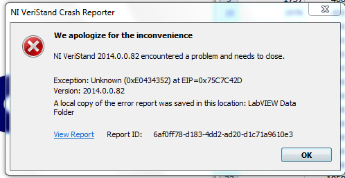
Help interpret the VeriStand crash report
If VeriStand 2014 is left on for a few days, he will break eventually. I run VeriStand on other test systems and very stable. On this basis, I am sure that the accident is related to a unique piece of code (custom, device model, etc.) or the installer for VeriStand on this test bench.
The error log is attached. I need help to interpret the error log to refine the question. Normally I would remove just a piece of code, and let it run to see if it crashes, but this project is big enough, it would take some time to solve the problems in this method.
Through the error log, I found this message, but I do not really understand how to solve this problem.
C:\Users\Public\Documents\National Instruments\NI 2014\Custom Devices\NHR Power Module Rack\Data\NHRDCPowerModule.dll VeriStand
ExtFuncDWarnOnCorruption: connectorTDR is
TDR (1/2): @0 x 0000: 'NHRDCPowerModule_ReadArray': 8
@0 x 0000: 'return type:
@0 x 0004: "Vi":
@0 x 0008: 'MeasurementsBufferSize ':
@0x000C: 'Measures': [V0]
@0 x 0000: ":
@0 x 0010: "method":
@0 x 0014: ' ValBuff
TDR (2/2): erSize':
@0 x 0018: "Val": [V0]
@0 x 0000: ":
@0x001C: ":
@0 x 0000: 'ValActualSize ':Little background for this project:
VeriStand deploys on windows for NH Reseach Power Supply target and she deploys on cRIO9081 with 9144 chassis EtherCAT. The project contains multiple models and custom devices.
This type of report should be sent to support NEITHER.
They could provide a solution to this, or at least be aware of this problem.
-
readings of Veristand instruments with a remote system
I'm new to the National Instruments and Veristand material and I'm trying to use an instrument with Veristand to see if I can get readings of this instrument. I use a PC with Windows Vista and I am connected via a network to a PXI-8108 controller in a PXI-1050 chasiss chassis. The instrument is just a thermocouple which I use to become familiar with everything. The thermocouple is connected and the connection SCB-68 block which is connected to a PXI-6221 multifunction data acquisition in the chassis. I am able to create a task in MAX under remote system and everything seems to work. What I want to do is to get the readings in Veristand, and I don't know if I need to create a custom device that is related to the acquisition of data somehow, or if there is another way to do it. I created the DAQ hardware in the system Explorer, but I see no way to link the real DAQ hardware on the remote system. I wonder if anyone can help with this.
All advice is appreciated.
Thank you
You can read the value of your thermocouple directly from VeriStand channel, but the process is different than using MAX.
In the system Explorer, add your DAQ hardware that is wired to your SCB-68. Make sure that you specify the same name (i.e. ' Dev1'), which is the make up something, you also that you have imported the peripheral canal which hangs to the thermocouple (i.e. "ai0"). There is no way in System Explorer to specify that this channel should be scaling of thermocouple. VeriStand initially served this string value value brute power. However, you can set the limit high and low for this channel to something small as +/-1V, since thermocouples have very small readings.
You add the balance to your system separately after the deployment of the system definition, you have created the target of RT. For this to connect to the target using the workspace and select the tool to the workspace on the Tools menu called channel scaling and Calibration Manager.
In this dialog box, you will see your TV listed DAQ. Navigate in the dialog box assign an appropriate scale of thermocouple to your channel. Once this is done, the target will remember the scale for this channel until what crush you.
I would like to know how it goes...
-
VeriStand missing in Simulink blocks
There are two computers I meet currently on this problem. I installed matlab + simulink then all my software from national instruments, including simulink interface toolkit anf NI Veristand 2009. I didn't completely install matlab before installing any software of NOR. I've done it before with other computers and everything worked. This time however the veristand blocks are missing in simulink. One of the computers that what happens on is 64-bit. It has 64-bit matlab (I couldn't get 32-bit matlab to install; according to mathworks 32-bit ML under 64 bit OS is not supported, but should work; See link below) and 32-bit NV. could it be a problem? The other computer is running a 32 bit OS. I tried to reinstall completely Veristand and blocks are still missing. Any suggestions? Thanks in advance.
http://www.MathWorks.com/support/solutions/en/data/1-1CAT7/index.html?solution=1-1CAT7
Hello Jon VT,
It seems you could faces two different problems. The first being that NI VeriStand is a 32-bit process and therefore cannot communicate with Simulink of 32 bits.
Second, NI VeriStand updates some files during installation that can sometimes be marked read-only, so it is necessary to do updates yourself for these features. This is described in the help topic communication with the NI VeriStand Server.
Hope this helps,
Angela M
Product Support Engineer
-
DAQ in Veristand readings do not match the MAX readings
I have three accelerometers attached to a block of SCB-68 connection that is connected to an NI PXI-6221 data acquisition on a RT system. I have created a task for each accelerometer in MAX and have tested each one to see that it works and gives appropriate readings. Veristand, I created a workspace file to test the accelerometers and I the acquisition of data created in the system Explorer. After the deployment of the system definition and running workspace, I created three simple graphics and connected ways appropriate to each curve. I reduced tensions in the same way exactly, I put on the scale the to the MAX, but for some reason, one of the accelerometers gives tensions that are far away from where they should be. The other two accelerometers work perfectly and one that does not works perfectly in MAX. So I don't think that there is a problem with the accelerometer, it just would not work in Veristand for some reason any. I wonder if there is someone who can at least have an idea of why something like this could happen. I have all three accelerometers that are related to the same connector block and I wonder if put too much in a block would do something like that.
Any help would be appreciated.
Thank you
For all those who can do I understand what the problem is. The default setting in Veristand read channels of differential measures, so anything connected to channels 8 or below is mapped to both channels, (e) and has (n + 8), where n is the number of the channel. For me to use the accelerometers in the way I set up the I just need to go to unique benchmark measures ended (CSR) in the system Explorer.
Once again thanks for your help.
-
the parameter mapping constant to a control block Veristand simulink block
Hello
I'm trying take a simple model of an RL circuit in simulink (build a DLL) and control of the constant blocks in Veristand to dynamically change the value of R and L constant through Veristand Slider indicator or digital. I can see the output of the model run, based on the initial values that I have loaded, but I'm not able to mapping of these parameters to any digital control.
Any thoughts on how to do this!
Hey, Trever,.
You must use a command of calibration model to interact with parameters, and not a digital control.
Take care!
-
I'm just starting to use the evaluation copy Veristand to see if it can do what I need it to do. It seems very customizable, and I tried to create controls in the workspace personalized with Labview. I would like to make things like radio buttons, lists and menus in the workspace to control my drop-down model. I have tried everything just by taking one of the digital controls and its replacement by one of the controls mentioned previously, but it gave me an error message saying they were not supported. It seems that I'd be able to do this using the free label template, but I'm not sure how to do this. I was able to find an example of a custom indicator (min/max one), but could not find everything related to custom controls. Are there examples or tutorials, that I could look at? How could I go for some of these controls of Labview in things that I could use the Veristand workspace?
-Eric
Hello Junior, I have some answers for your problem.
1. I have attached a zip file that contains your renamed control and build a project in it. You should be able to unpack, check the construction features and make sure that the output destination is C:\Documents and Settings\All Users\Documents\National Instruments\VeriStand\Display models. Trigger a build on that and you should get EricHettlerSample - Radio.vi and EricHettlerSampleControlSupport.llb in there. Once you have this launch a workspace, you will be able to drop the EricHettlerSample - Radio in the control list control.
2. for the explanation. I think that when you perform a save as on the example of the min - max you download the Web of LabVIEW cross link on the screws that the llb with that of the vi.lib. Do a save as will not work. What works, it is that you create a project and setup a source distribution to generate the custom control. Here are the steps that I have take based on your attached file:
- Rename in windows Explorer, the attached digital indicator - radio.vi to EricHettlerSample - radio.vi
- Open LabVIEW convert the .llb you connected to a directory.
- Create a new project file.
- Radio.vi open EricHettlerSample - under my computer, when LabVIEW invites me to some VI I search in the directory to convert llb. Note that LabVIEW search more files under vi.lib because these are the files that NI VeriStand install labview directory.
- Once I added some of the screws, I mass compile the project.
- Create a source distribution. Add the EricHettlerSample - radio.vi. Go to setting source file main vi for the folder models and all otherwise go to a folder of llb.
- Trigger the build, LabVIEW will do a better job in creating an isolated component which is properly connected.
In General, you always want to create a project to create a custom, control given that Save As not always worked with the LabVIEW VI link in NI VeriStand.
To create a completely custom control project base what you do is:
- Copy C:\Documents and Settings\All Users\Documents\National Instruments\VeriStand\Display Templates\Decoration - free Label.vi in Explorer windows in a directory of your choice.
- Make a change of name on VI in Windows Explorer.
- Open LabVIEW to create new project add the renamed VI in my computer. This will create an empty project to customize the custom controls.
I hope this helps, let me know if it still does not for you.
Also if you still embarrassed by the error messages appears so you will want to clean directory C:\Documents and Settings\All Users\Documents\National Instruments\VeriStand\Screens this directory being where NEITHER VeriStand puts all the controls that you drop into the workspace cache. So if you have a control that cannot be loaded remove all screws in this directory should remove the wrong screws.
-
Compatible for the cRIO 9063 VeriStand?
Hello
I currently have Veristand 2014 installed, but I'm not able to install veristand engine to MAX.
My 9063 cRIO is compatible for Veristand?
Thank you
Support for targets cRIO that running the NI Linux operating system real-time has been added in 2015 VeriStand
-
Custom device error VeriStand-307603: no specified main page?
I get the 307603 error when I try to add a custom device, I developed a VeriStand project on a client computer. The message error window States:
«Error 307603 occurred at Custom Devices Storage.lvlib:Initialize New Custom Device.vi > Custom Devices Main Page Data.vi Storage.lvlib:Get.»
Possible reasons: NI VeriStand: the required custom device doesn't have a specified master page. Contact the creator of custom feature to correct the error. »
I get this error when you add the device custom VeriStand on my development computer; only on the client computer. I tried to copy the custom device built on top of the client computer and the custom device of source based on the customer's computer. I also have three other devices custom that I developed that work fine on the same computer, so I don't know why it does not work. I checked the specification of the build configuration to ensure that the VI home page is included in the source files, and to generate test preview shows only the custom device LLB and the XML from the file in the build directory, as expected. The XML file is also oriented the correct path for the homepage VI and the GUID in the XML is the GUID file matches in overall search GUID variable. I can't think of anything to check.
Development computer:
Windows 7, 64-bit
LabVIEW 2011 SP1
VeriStand 2011 SP1
The client computer:
Windows XP SP3, 32-bit
LabVIEW 2011 SP1
VeriStand 2011 SP1
Everybody knows such a question or give me additional troubleshooting tips?
I got it to work, but I don't know exactly what the problem was. I made a copy of the part of the XML file that adds the device custom menu right-click and commented of the original, then edited the part I copied it to give the device custom a different name in the menu. It worked fine on my development computer at the time I made the change, so I thought it was OK. I just went and restored the file in the original version and now it works on my customer's computer.
Maybe you are looking for
-
Satellite A300D-13R - support metal Secundary HDD
Hi all I have a Toshiba Satellite A300D - 13R paskoe.Well, my question is where can I get the metal Secundary HDD support that goes with 4 screws to fix the disc... If I have SATA connectors? Because I can't find any site for purchase. Thank you
-
Lost the disk for recovery of Windows 8 for Satellite C855 1v9
Hello I bought a new laptop (toshiba satellite) 8 original windows pre-installed,However, I wanted to repartition my hard drive and without warning I deleted the recovery partition, therefore, the laptop could no longer starts. So I asked a professio
-
How to remove "Graphics" copper copper
Hello! How I cut out the plan copper? When I use the normal function of the polygon, there is always a small chain copper all around the polygon and parts. Using the Dungeon/Keep-out tool, I get errors when I put on parts/vias/nets... What is the cor
-
can not get updates because of error code 80040790
How can I get updates when I get an error code 80070490
-
Windows Media Center does not detect my TV tuner card
Hi a few years back, I built a Media center PC Windows Vista worked great! incredible experience recently (2 months ago) I formatted the PC and reinstalled Windows Vista now Media center options have changed and my Tuner card is not be detected BUT i