Wait signal generator complete the scan list before sending the next command
I am writing a program for Agilent E4421B signal generator scan to list between a range of frequencies (ramp up to the maximum frequency and then back down to the original frequency) specified. The signal generator has only a list of 401 points, which is a problem when I want to wash over a wide frequency range. To work around this problem, I would like to perform several scans of list in a row. However, I can't figure out an effective way to "say" the program to wait until the previous scan has finished before sending a new order of scanning for the signal generator. Any ideas? For reference, I use Agilent ESG drivers series LabVIEW.
Thank you!
If you use standard VISA calls, I would say just that send the scan command, but add; * mutual fund? (operation ends?) make a query. Then, run a VISA to read what's coming. This indicates to the device to send a 1 to the output buffer when the scan is complete (or just about any other operation, also). As you are waiting for a response, your computer will wait the amount of time to wait so he could see a response, it is not less, your way with the exact amount of time - no more - to be actually taken.
A few warnings:
(1) make sure that the time-out is longer than the length of most slow scan.
(2) there are variants of the '1' being returned. I saw '1', '01', and even "1.00E + 3" therefore to allocate more than one byte to read."
Tags: NI Software
Similar Questions
-
Device requires two characters of endpoint to complete the "READ" command
Hello, I'm the Labview programming, an application to receive data from a device series. One of the problems is that the unit always displays CR + LF after each measurement. However, in Labview, it seems that a single character is allowed. This causes problems for me, because when I choose LF as the stop character and I'm scanning the reading string, it contains the other termination character, who is sent to my data table, file and waveform, and it also fails to plot the data in the table of waveform, since the digital channel is not pure numbers.
Is there a way to get around this? Thanks for any help.
Define LF as your character to terminate employment. Search for the string of the CR function and return the data before the CR.
-
"Could not complete the Photomerge" error message
I use PHOTOSHOP CS6 (64-bit) and WINDOWS 7 ultimate (64 bit) when I trie to use Photomerge I have this message:
Cannot complete the Photomerge command because Photoshop was unable to find the plugin JavaScript
Try this:
http://forums.Adobe.com/thread/1233874?TSTART=0
If you have more problems, you will need to provide more details.
Mylenium
-
Can we start a P2V and check the result the next day?
We will conduct P2V to a number of physical machines. We plan to start P2V at around 18:00 and if it works well for 10%, we will check the result the next day. Is this OK or we should keep an eye during the conversion?
Thank you
Personally I would keep an eye incase there is a problem that can be solved, but if you feel confident it I no reason why you can't let this run and see if she successfully completed the next day to remember if it does not you may have a few waaiting furious users for you.
-
Shuffle resumes songs before completing the reading list
Hello!
Since I upgraded my ios to 9 (a few days ago) my music application behaves differently.
I'm still using the 'Random' option, but given that 'upgrade' songs are repeated frequently. There is no more "Song X on Y ', only of songs randomly with frequent recurrences. He did not finish the playlist until I hear the same song again, and it happened a few times that only after 20-30 songs the same song appeared again.
It's a nice feature to see the history of played songs and to see songs that are install next - but there again I can see rehearsals. A song I heard is coming up next. (and no - I did not duplications of the same song on my playlist).
What can we do about it? I don't want to downgrade my ios just because of this, but it is unbearable.
Can I pick up the the old behavior without downgrade my ios?
Thank you.
-Switch to view playlists in-app music
-Launch the playlist
+ Click the thumbnail of the playlist, or
+ Press the 3-ball icon on the right, then press play then, or
+ Tap the 3 ball on the right and press Add in the next place
[Close to that I can tell, if the queue is currently empty, all three of these options behave the same.]
-Bring up the player screen
-Press on the small icon to the next to bring up the screen to the top next
-It will read: "up NEXT: PLAYLIST {name}".
-Press clear and confirm by pressing 'Clear Up Next. "
-Press "Done" to exit the screen to the top next
-You should be back to the display of the player with whatever the currently playing song
-Go back to where you started reading list from and this time, whether you want to use:
+ Play the 3-ball icon on the right and tap Next, or
+ Added the 3-ball icon on the right and tap in the next place
-Make up the screen of the player again
-Press on the small icon to the next to bring up the screen to the top next
-It now reads: "up NEXT: SONGS {# of songs}.
-
How to synchronize the start of IT and relaxation the Scan list (DAQmx Switch)
Hello
I want to measure samples of N to the AI0 of Council NI PXI 4461. The measurement starts on a rising edge of a digital triggering provided to the PFI0 of the same Board. The measure is configured with samples of N/2 pretrigged. So far, everything is under control...
Using an NI PXI 2567 Board, the signal applied at the entrance the 4461 (AI0) switches between a V2 and V1 signal. I would like to synchronize the switch between the two signals with the trigger signal applied to the input of the PFI0 Governing Council 4461. In order to obtain samples of N/2 of V1 and V2 samples N/2. Synchronization of 1 to 5 ms would suffice!
My question is how to synchronize the start of acquisition of AI pretrigged of 4461 with the switch control given by the Council of 2567?
Thank you in advance for your help...
PS: the configuration of the system is:
-LabView 8.5
-Chassis PXI-1044
PXI-4461 on slot 2
Module 4-slot PXI-2567
Hi Frederic,.
I came back to this recently and used the following examples to run the desired synchronization.
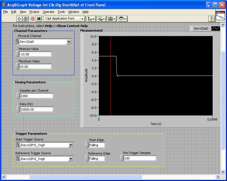
PXI-4461: Acq & graph tension-Int Clk - dig Start & Ref .vi
Samples per channel = 1000
Rate (Hz) = 10000.00
Start the trigger Source = / [name of the instrument DAQmx] / PXI_Trig0
Onboard start = fall
Reference Source Trigger = DAQmx Device Name] / PXI_Trig0
Reference edge = fall
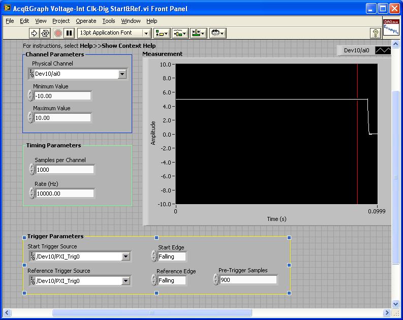
Trigger samples = Variable (100, 500, 900)
PXI-2567: Switch Scaning-SW Trigger.vi
Advance the output terminal full = / [name of the instrument DAQmx] / PXI_Trig0
Scan list = / [name of the instrument DAQmx] / ch0-> com0.
Scan list = / [name of the instrument DAQmx] / ch1-> com1;
Hardware configuration:
The PXI-2567 module controls an external relay that switches between the voltage of 5 V on ch0 and ch1 0 V.
The PXI-4461 connects to the COM of the external relay and therefore reads 5V when ch0 is connected; 0 v when ch1 is connected.
Procedure: The above examples are used in the following procedure.
1. run the PXI-4461 VI. A start trigger (falling edge) is necessary to start collecting samples before firing.
2. launch the module, PXI - 2567 VI. When ch0 is initially (and immediately) on com0, a trigger is sent to PXI_Trig0. The PXI-4461 will begin to acquire samples before firing.
3. - click on the "Connect to the next" button on the front of the PXI - 2567 VI module. This sends a trigger to entry software for the PXI-2567 module and the transitions of the scan for ch1-> com1 list. Once the PXI-2567 module remains (debounced), advanced complete relaxation is sent on PXI_Trig0 for the PXI-4461. The PXI-4461 will begin to acquire samples after outbreak.
Note: Instead of the trigger of the software entry, an external input trigger can be used (e.g. PXI_Trig1).
Results:
> Before instant release of samples = 100
Delay is caused by the time of actuation of external relay.
> Before instant release of samples = 500
Delay is caused by the time of actuation of external relay.
> Before instant release of samples = 900
Delay is caused by the time of actuation of external relay.
I hope that the attached screws and the explanation above helps you and/or other customers who have this problem.
Best regards
Chad Erickson
Switch Product Support Engineer
NOR - USA
-
HP OfficeJet 6700: Could not complete the scan
I used this Toshiba Satellite P55W-C laptop sucessfully for scanning and printing since I was 6 months ago and had a very easy installation. They are entirely compatible.
Printing now works fine.
I was in the Middle I digitizes a 7 page paper on the feedbed in TIF format, (which I did successfully several times before) when he leaves the analysis. I had to pull the output printer page.
I could click on new scan and go to the properties of a couple of times, but it is not yet complete the scan.
Now as soon as I click on "new scan" I get a pop up window that says "unable to complete scan.
I am able to complete the scan with my laptop HP G72 5 year (after the start of an hour of time), this scanner is fine.
What happened to my computer?
Hello and thanks for trying to help.
They were always connected wireless.
I does not solve the problem, after having paid Best Buys Geek Squad $100 to register for a program.
It remote access to my computer. He had to remove all the drivers for my printer and then reloaded them and it worked fine. I thought I had done this, but all I did was to remove the printer from the list of printers and devices. I had not actually entered in the list of programs and deleted all the driver and related information.
I hope this can help someone else.
-
Duplex charger HP 8620 document Mac error - 'the scanner could not complete the scan.
Hello
When the analysis attempted double helped since the document feeder, I get the following error:
the scanner was unable to complete the scan
If I don't select duplex option, the printer scans very well. I really need the duplex feature was that the printer was purchased for.
I uninstalled the printer, reset and all that gubbins.
my setup is the following, configure the printer as wireless on mac osx mavericks last generation last drivers/HP utility. Ipgraded for the latest firmware of the printer also. all without success, and now support is not open until Monday

For more information on this...
So I think that I managed to fix it. Different solutions etc. then forums all about I thought I would include it here. This is the steps that I found to work for Mac OS x 10.9.
I need to follow the steps:
- Remove the power cable while the printer is turned on wait about 15 seconds and plug it in again.
- When the installation of the printer using the selection HP not the Airprint, which is added by default on Mac OS x 10.9 - capture screen attached and operating.
If everything is working great and then if not go to step 3.
- If the printer is already installed with AirPrint go to the printer main & scanners, right click in the box on the left where you printer is displayed and click on reset printing system. -This will remove all printers found here also.
- Download of the latest version of the software for your operating system
- Install the software, restart the computer.
- Download the latest firmware, if it is available for your printer
- Add your printer and follow the steps 1 & 2. It should work and allows you to copy double-sided.
Don't know if this is a limitation of the software or drivers but ADF allows up to 300 dpi, as the manual scanner allows all the way up to 1200 dpi.
See you soon
Ed
-
How to control each channel of the signals emitted by the generator of digital waveforms?
Generator has digital waveforms of 8 channels. I need to generate two different signals for HSDIO. How to change and control two different ways? In addition, how to translate pinout of the PXI-6541 to channels? I need pin 1,3,29 and 31 control signal individually.
Thank you!!
You need to combine your personal data in a table. The digital waveforms is simply a numeric representation of the binary table. It always boils down to bit 0 of each element of the array will channel 0 (or the first string that you specify in creating dynamic channels). The next bit goes to the next channel. My last post is very clear. To display the table in binary, right-click on a table element, then select the display Format, then select binary. You can also right click on the element, select Visible, then select Radix Show to display the small b before the number. One last thing, in the display Format window, uncheck the box next to the minimum field width to use. Then set the digital just below zone 8. Then select Pad with zeros to the left in the box below.
You should not use waveforms up to what learn you more about how the HSDIO operates on the input data. It is not difficult to combine waveforms, but it is not as clear as it is using an array of U8, U16 or U32.
Trying to explain further. The first number to be written to the HSDIO will have this effect: Bit 0 (LSB) of the number is written to the first HSDIO string you specify. Bit 7 is on channel 8, you specify. If you specify no 8 channels, the bits download ignored. If wiring in a certain number will produce only a single bit on each channel. In other words, the number has already combines the bits of all channels that you specify. Combine you do nothing yourself. Return to my photo on my last post. By wiring in a table, you cause a binary model must be generated.
I hope that is more clear.
-
I'm still on dial-up. When I try to download a game, the download is so slow that my connection times out before it can complete the download. What can I do to speed to the top of my download?
Change your broadband connection. You can't wait to download a game on DIALUP! Or use a download manager for the moment.
http://www.internetdownloadmanager.com/
If this post answers your question, click mark as answer .
-
Application of a policy of VSG when the vector signal generator is offline?
How policies are applied when a vector signal generator is offline, make port profiles with an attached policy start VSG to abandon all traffic until the vector signal generator comes back online?
VPath and vServices configuration
The default value of failmode is close.
Fail mode specifies the behavior when the MEC has no connectivity to the service node. The default fail mode for ASA 1000V and VSG is narrow, which means that the packets will be dropped. The default failure of vWAAS mode is open, which means that the packets will be passed. service nodes vPath 1.0 does not support service chaining. When you use a vPath 1.0 service node in a string, traffic to that node goes into failure.
Thank you
Responsible Dan
Cisco IDP data center
You want to know more about how the PDI can help you?
http://www.YouTube.com/watch?v=4BebSCuxcQU&list=PL88EB353557455BD7
-
How to complete the list of values when loading screen
Hi all
I have a list of values based on another field (ANOTHER_FIELD).
for example
Select the value d, r
from table_name
where id =: ANOTHER_FIELD;
ANOTHER_FIELD has a default value.
But when the screen is opened to the list of values does not have the default value and the values list is empty.
Just when it is filled with submission of the form, the list of values.
Please tell me how can I complete the list of values when loading screen.
Thank you!Hello
It depends on how you have defined the default value for ANOTHER_FIELD.
I always set my default settings using a calculation, that runs before header, on the element that defines the value using a static assignment, but to ensure that the calculation is dependent on the order of the day being NULL - try this
Andy
-
With the help of the external RF signal generator
Hello.
I just want to ask how can I remove the frequency shift if I use an external RF signal generator (instead of the RF PXI-5652 signal generator module). I understand that in the case using the OR to generate RF signals, frequency shift is deleted by setting the same source of reference for the transmitter and the receiver clock (placing the clock source of reference to PXI_CLK of the façade of generation VI and VI of the acquisition).
Thank you very much.
Hi Betty,.
In this case, no changes are needed, such as modules OR still use background clock basket PXI as the ref. clock source If you are still having a frequency shift, you probably need to configure sig gen to lock a clock external REF. Usually, just make the connection of the signal is not enough - you must also indicate the sig gen to use the signal connected to the input clock ref. Terminal
If you use the sig gen as clock source master Réf, connecting the 10 MHz of the gen of GIS at the BNC 10 MHz IN on the back of the PXI chassis replaces the clock native from the newly connected with the PXI chassis backplane, and analyzers are still using the clock background basket PXI as the source clock Ref (no change to the SW settings).
Kind regards
Andy Hinde
RF systems engineer
National Instruments
-
Output a TTL HIGH 10 usec via the PFI port on AWG signal generator
LV dear community,
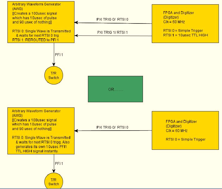
I want my signal generator (PXI-5422) to produce a pulse of 10usec with its PFI1 range each time that a wave of exit CH0. The frequency of repetition of the CH0 impulses and the port of PFI1 is 10 kHz. Is it possible for the signal generator automatically generate this HIGH TTL signals for usec 10 on the PFI1 line all at the same time produce a long-wave 100 usec?
Another approach, that I'm considering is to re - route a pulse of RTSI1 (10usec) from an FPGA and output via port PFF1 of the GTS. However, I doubt that this is possible, as the HELP MENU for the working group said that the report can only occur when the Working Group is in "idle" mode.
Any help will be greatly appreciated!
Have a nice day
 I have attached a diagram of operation that hopefully, explains what I'm trying to do a little better. Once again thanks for looking!
-Daniel
Hi Denn_Mann,
To get around the limit of 320ns, you should be able to use scripts with the FGEN markers to achieve your goal. Anything you want to do is use of script with markers in alternating mode. You may want to toggle high then low rocker after the number of samples you want pulse is high while your signal is present. I've linked some information below that should be good resources for script for you if you are not familiar.
Trigger on the arbitrary signal generators and advanced waveform sequencing
Creating an event marker in Script Mode
Script mode
Example of the expedition: "Fgen Arb Script.vi.
Kind regards
Ann Travis
-
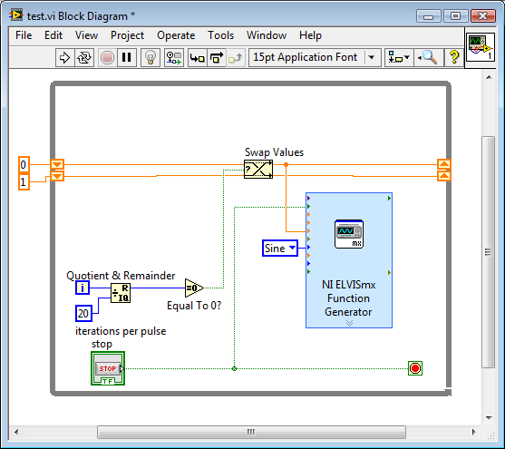
How to generate a pulse with the signal generator?
Hello
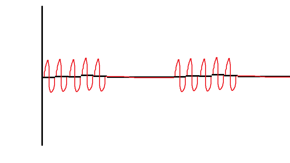
I would like to ask if anyone knows how to use the Elvis platform to generate a regulated pulse wave?
It should look roughly like the picture above. A sine wave with the regulation.
Anyone who can answer my question please respond to my post.
Thank you.
You are using LabVIEW to generate the waveform or using the Soft front panels? In LabVIEW, you can use the express VI generator function and specify the Type as "Sine". Then, simply change the amplitude of the sine wave. During the actual pulse, the amplitude would be what you want (i.e. 1 V) and while the pulse is idle, set the amplitude to 0.
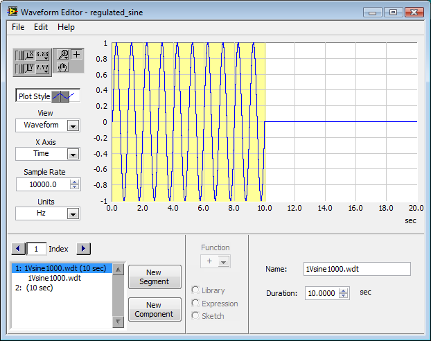
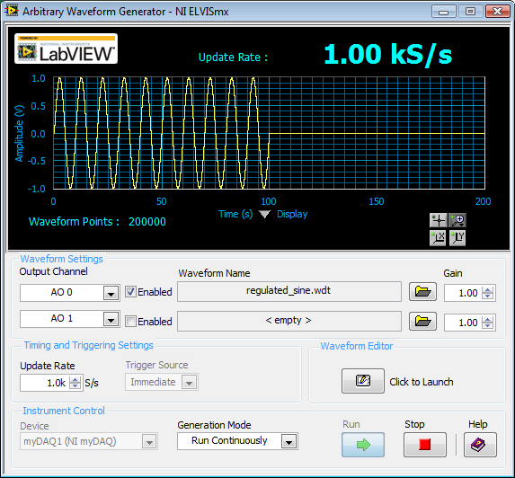
If you use the soft front panels, you can use the Waveform Editor to create a waveform that includes a sine wave for the length of your pulse and then the values of '0' for the rest of the time. Then use this waveform in the flexible front of the arbitrary signal generator. Simply create a component of sine as the first part of the wave and then add another element to a level DC '0' for the rest.


Maybe you are looking for
-
For legal purposes; How can need to research papers of Firefox, I contact Firefox to request?
In the case of a death where documentation is necessary for legal purposes, I understand my copies of emails and screenshots of the (favorite) web searches are not considered valid. The Court requires Firefox documents to prove that what is in an ema
-
Why 'Apple TV' is listed twice under 'speakers '?
For some reason, 'Apple TV' is listed twice under "Speakers" when I slide down (playing a video) to get to the Audio settings (see image). The first 'Apple TV' is selected by default, which sends audio to the TV via HDMI, which transmits to my bar of
-
Problem to run a Labview program in another pc
Hi dear, I am a beginner in Labview. I have a program made by a colleague. It works fine on the PC where it was written. When I copy it to another PC, it runs. but he can't write and read the right settings and values of the instruments. Labview vers
-
My computer guard shut down after use of a few minutes.
My computer guard shut down after use of a few minutes. When I re - start insiders 'fix the beginning upward.'
-
Can win 7 32-bit Home Basic Upgrade to 10 64-bit windows?
I wanted to know that if can get a free upgrade to windows 7 32-bit to 64-bit windows 10. I was wondering if only 32 bits can get only update for 32-bit or 64-bit also. Any help would be greatly appreciated.