withdrawal of a th ack PXI module
I need to send some PXI modules for calibration but am unable to get off the PXI rack PXI modules and rather
to force these and potentially break.
I googled for how to remove the PXI modules, but unfortunately, I can only find online information about how to install the PXI modules.
Can someone send me a link to any documentation OR how to uninstall the PXI modules from a PXI square?
Thank you
Too bad...
I just found out that National Instruments skillfully hid a mounting screws out of sight under the level of edjector
and then took the trouble of this document anywhere on how to remove a PXI module in order to improve the
customer experience.
...
Tags: NI Hardware
Similar Questions
-
Analysis of information for the PXI Module
Hello
I intend to develop a labview program that is analysis drawn from all the module present PXI chassis (such as calibration, description of the add-on dates, etc...). Need some advice which VI Labview is capable of scanning over the disclosures in which the output is "chain" so that I can
manipulate the program labview himself. As a search for VI, one option that I see is the 'MAX Generate Report', but the results are HTML or xml (as well as my PXI
crashes when I use this feature).
Appreciate any inputs on this.
Thank you
Versil1
Hi Versil1,
I advise to use niModInst, DAQmx and DAQmx system device nodes. Examples of these functions can be found here:
niModInst: the device name of query by programming or other information using the API OR-ModInst http://decibel.ni.com/content/docs/DOC-7454
Device node and DAQmx system: programmatically obtain product DAQ device http://decibel.ni.com/content/docs/DOC-3716 names
For the outputs that are not in the string format (i.e. DevNames), you can use the flatten the string function to convert them to strings.
Kind regards
-
Position of the PXI Module in the chassis
Dear Forum,
I just got a new PXI-1033 chassis as well as a single PXI-6259 HAVE/AO/DIO and two PXI-2501 switch modules module.
No matter where I physically place these three modules in the chassis?
Sincerely,
Zach
Zach-
So, I see you have a PXI-1033 chassis and two modules PXI (PXI-6259 and PXI-2501). In this case, their placement is not serious. Just a tip: If you consider the symbols in each slot, they indicate what type of device they can accept.
A symbol of circle, the location is a generic peripheral location. A generic device location will work very well for both of your devices.
A symbol of diamond, that location is a location of triggering star.
A symbol of diamond with a circle inside means that the slot is a generic peripheral location with star triggering capabilities. This slot machine also works for each device.
I found these definitions of machines slot in user guide NI PXI-1033 and specifications. Check it out if you want more information than what I have provided.
See you soon!
-
A PXI Module will work in a chassis/slots SMU
Simple question and the title says it all really. I'm 99% sure that it used because I do not know the connector backplane is different but thought I would ask for clarification.
Congratulations in advance.
Mitch
The connector backplane is totally different between PXI and SMU. However, most of the SMU chassis of NOR have hybrid slots that accept a card PXI or SMU.
-
PCI-6035E recording in MAX as PXI module
Hi all
I have some difficulty to identify and use an NI PCI-6035E data acquisition. Data acquisition is not save in MAX as a DAQ hardware, but rather as a PXI system. It is listed as PXI4::1:INSTR (PCI-6035E) as shown in the attachment.
On the same PC, I use an NI PXI-1033 chassis related through a card PCIe-8361. However, even with the system disconnected from the PC the DAQ PXI still fits like a PXI system.
My computer is running in some kind of conflict between the two devices? We want to run the two together. Currently I'm under MAX 4.3 and LabVIEW 8.5 on Windows7.
Any help would be appreciated.
See you soon.
How PCI-6035E appears in Device Manager? Screenshot of which can be useful if these steps do not work.
Also, what version of DAQmx do you have? If you don't have DAQmx 9.3, update your device driver by going here and download the driver. I assume you are using an operating system that is compatible with this driver.
If you have DAQmx 9.3, try to remove the card from your computer, delete the PXI chassis in MAX and then installing the card once again, but to a different PCI slot.
-
How to build a parser of vector signals PXI using different module combinations
Normal
021
fake
fake
fakePT - BR
X NONE
X NONEMicrosoftInternetExplorer4
/ * Style definitions * /.
table. MsoNormalTable
{mso-style-name: "Table normal";}
MSO-knew-rowband-size: 0;
MSO-knew-colband-size: 0;
MSO-style - noshow:yes;
MSO-style-priority: 99;
MSO-style - qformat:yes;
"mso-style-parent:" ";" "
MSO-padding-alt: 0 cm 0 cm 5.4pt 5.4pt;
MSO-para-margin-top: 0 cm;
MSO-para-margin-right: 0 cm;
MSO-para-margin-bottom: 10.0pt;
MSO-para-margin-left: 0 cm;
line-height: 115%;
MSO-pagination: widow-orphan;
font-size: 11.0pt;
font family: 'Calibri', 'sans-serif ';
MSO-ascii-font-family: Calibri;
MSO-ascii-theme-make: minor-latin;
MSO-hansi-font-family: Calibri;
MSO-hansi-theme-make: minor-latin;
mso-fareast-language: EN-US ;}Normal
021
fake
fake
fakePT - BR
X NONE
X NONEMicrosoftInternetExplorer4
/ * Style definitions * /.
table. MsoNormalTable
{mso-style-name: "Table normal";}
MSO-knew-rowband-size: 0;
MSO-knew-colband-size: 0;
MSO-style - noshow:yes;
MSO-style-priority: 99;
MSO-style - qformat:yes;
"mso-style-parent:" ";" "
MSO-padding-alt: 0 cm 0 cm 5.4pt 5.4pt;
MSO-para-margin-top: 0 cm;
MSO-para-margin-right: 0 cm;
MSO-para-margin-bottom: 10.0pt;
MSO-para-margin-left: 0 cm;
line-height: 115%;
MSO-pagination: widow-orphan;
font-size: 11.0pt;
font family: 'Calibri', 'sans-serif ';
MSO-ascii-font-family: Calibri;
MSO-ascii-theme-make: minor-latin;
MSO-hansi-font-family: Calibri;
MSO-hansi-theme-make: minor-latin;
mso-fareast-language: EN-US ;}I understand
Vector signal analyzers OR consist of 2 or 3 separate PXI modules: 1
digitizer, 1 buck converter of RF frequencies and 1 generator of signals (model 5663).1. can I use digitizer and signal
generator general purpose oscilloscope and generator of signals separately?2 may I build my own VSA by choosing
different combinations of scanners and the signal generators? Or replace the signal
generator by an arbitrary signal generator?3. I
intend to buy a digitizer/oscilloscope and an arbitrary signal generator
analysis of response of frequency on the transformers. Later I plan to
buy a step-down converter frequency and build a vector signal Analyzer. Is this possible?Hello
The frequency IF the 5660 and 5661 (it's the same thing) is 15 MHz, with an instantaneous bandwidth of 20 MHz. The difference between the 5660 and the 5661 is located in the digitizer that accompanies it. The 5660 uses the PXI-5620 digitizer that has a sampling rate 64 MECH. / s and a buck converter of digital frequency limited to 1.25 MHz of bandwidth. The 5661 uses the digitizer PXI-5142, giving you a MECH 100. / s rate and a PSO allowing digital downconversion circuit and the decimation of the full bandwidth of 20 MHz.
The common comment in the SBA above is the RF PXI-5600 frequency step-down converter which is a superheterodyne architecture of three floors. OL is for the three stages of this module are auto-approvisionnées in their own country. The architecture of several step allows for rejection of the improved image and filtering at the expensive of a noise floor slightly higher due to the signal path more complex. There also an OCXO on board, this gives him a time reference more precise - noise reduction phase etc. The PXI-5600 by itself is wide from three locations.
The SMU-5601 since SMU-5663 step-down is designed based on the single frequency step-down converter and resumes from a single location. The celled frequency step-down converter gives you improved noise floor characteristics and a better dynamic range, with the rejection of the image fees, having does not simply because there is only one step. The LO is provided by an external module in this case for several reasons. Have a separate external LO allows more modularity in your system, as well as the ability to share a single LO generator between several vendor-specific attributes. This opens the possibility of MIMO applications. The internal of the NI PXI-5600 LOs are not shareable and therefore cannot be synchronized between several PXI-5600 s. The PXI-5663 (all three modules) takes up the same amount of space in the slot as a single NI PXI-5600 without a digitizer.
The PXI-5154 is indeed a powerful scanner, given its instantaneous bandwidth of 1 GHz. Remember, however, that the connector Active Directory on this digitizer is 8 bits, compared to the 5622 which is 16-bit. If you need more resolution is of course entirely depends on your application. The PXI-5600, as SMU-5601 is controllable as a buck converter stand-alone frequency using the DAMA API OR. You will need to program your application with the scope API for use with PXI-5154 OR and the API de DAMA. A few other caveats to note is that there is no PSO on the PXI-5154 so you can't enjoy the Equalization filter to correct the frequency of the NI PXI-5600 response. Also, as I mentioned above, the frequency of YEW of the NI PXI-5600 has 15 MHz with a bandwidth of 20 MHz - processor 1 GHz bandwidth on your digitizer will be somewhat of an overdose of the IF signal.
While you're dead on with the advantage of modularity, I would take the time to really meet your search application and ensure that different choices of module and their combinations to meet these needs.
Hope that helps!
-
How to set up the PFI lines as input to PXI-6713 module
Hello
I have 6713 PXI module in my chassis PXI-1044. I have configured the PXI-6713 module to geneate some analog signals to my Board of Directors.
Council inturn process this analog signal and answers in return the status signals through a registry to the Board of Directors. In my application, the status bits in the register state of the governing body are mapped on the PFI 0:3 bits of the PXI-6713 (pins 11,10, 42 and 43) module.
My query is how can I configuration lines PFI as 6713 PXI module entries to read these status bits?
May be less than the explanation could give you little more information w.r.to my request.
When I use NI USB - 6008 module to read the same bits, because this unit has 12 e / s digital, I was able able to read the status bits in the last 4 digital lines by setting up those digital lines as input.
In the PXI-6713 module, I have only 8 digital lines. These 8 digital lines I used to send digital signals to the Board of Directors. I find myself with no digital i/o. Therefore, I could not use these digital lines. I'm left with only one option to use. Joana re PFI lines. Also the bits of status in the axis of the room are mapped such that the bits can be read through the PFI lines.
I was wondering do we have any example code to use inorder to read these status bits to the Board of Directors using the PFI lines.
Please let me know if you need more information to help out me.
Thank you.
Hello
When using the PFI PIN as input, you can individually configure each PFI for edge detection or level and the selection of the polarity. This information of PFI are referenced in the manual of Series DAQ Analog Output on page 6-1 (http://www.ni.com/pdf/manuals/370735e.pdf). Unfortunately, the PXI-6713 PFI lines are able to time a signal input and output for functions, AO or counters/timers. The ability to create static DI of the PFI lines is not available for the PXI-6713. However, some cards have this capability. The latest National Instruments products with PFI lines have the option of setting as PFI lines:
- Static digital input
- Static digital output
- Input signal of sync for functions HAVE, AO, DI, or counters/timers
- Output signal of the calendar functions HAVE, AO, DI, or counters/timers
(http://digital.ni.com/public.nsf/allkb/14F20D79C649F8CD86256FBE005C2BC4)
When the static value such as DIO, PFI lines are assigned to a different port (for example. PFI0-7 is Port1). More details on this subject can be referenced at:
http://digital.NI.com/public.nsf/allkb/DA2D3CD0B8E8EE2A8625752F007596E1
http://digital.NI.com/public.nsf/allkb/862567530005F09E8625677800577C27
-
PXI-5114 can hold in the SMU 1085 chassis
MY company plan to purchase the chassis SMU 1085. But we also want to use PXI module: PXI-5114, PXI-5404, PXI-5406 and PXI-6723. The image on the Web site, say they cannot insert into the slot of the chassis SMU-1085 Hyberid? Is this true? I want to be clear on this before we buy.
Thank you
Hans
Hello Hans,.
Each of these modules is hybrid compatible. The devices are equipped with the small connector XJ4. One thing to note is that the PXI-5404 (778577-02) is the compatible version of the hybrid.
The page linked below deals with hybrid compatibility further in article 2.
PXI-5404 (778577 - 01).
-
Good afternoon
I need some clarification on the simulation of PXI via MAX. I have several PXI modules and a PXI-1033 (integrated into the PCIe MXI) chassis on command. As they will take several weeks to arrive, of course, I want to simulate these devices and to start building screws
If I understand correctly the information contained in the knowledge base and forums, all I have to do is to simulate modules PXI themselves in MAX and nothing to simulate PXI-1033 chassis.
Is this correct? Guarantees as to any would be greatly appreciated!
Sincerely,
Zach
Hey Zach,.
You are right. We cannot simulate a PXI-1033 chassis, but because it's just an expansion chassis, there is no need to. You can simulate the modules themselves in MAX under DAQmx devices and then you should be able to start writing code.
Good luck and thanks,
Ryan
-
I use PXI - 1042 s with PXI-8196 embedded, each with several PXI modules installed controllers. (PXI-2530, PXI-4070 PXI-6509 etc..)
Is it possible to connect somehow to a laptop that has LabVIEW installed, such that I can develop applications (on the laptop) to control PXI modules?
When applications are completed and compiled in executable files, they will be installed on the PXI controllers.
I don't want to do, is to install LabVIEW on each PXI controllers I have to develop applications.
Kind regards.
You can develop your application... virtually simulating PXI modules - sounds interesting, but how to do this? (Or is it a matter for another post?
To simulate the device go to MAX > right-click devices and Interfaces > NOR-DAQmx simulated device > select your device and enter ok.
... but if you were to buy a PXI MXI-Express kit you can remotely control the PXI chassis - I think that's what I was looking for. But wouldn't this "work around" the on-board controller and have the executable running on the laptop instead? Looking at the link you posted, it is worth further investigation
It will bypass the controller for development purposes, but when you have generated your executable you can just charge on the PXI controller and it will run without the need of the laptop.
Kind regards
-
PXI-8431, without going into fashion with VB6 reception
I use a PXI-1045 chassis with a PXI-8431 RS422/485 card and communicating via a VB6 program
Send the output of the PXI-8431 RS485 module works well when it is in mode, the signal levels are approximately 1v and 3v for high and low, but when it is in fashion, that the outputs remain to 1v and 3v instead of going in passive mode and the two floating lines at approximately 2v with approximately 300mV differential as it should receive. This means that when remote devices send, the amplitude of the signal is about half as they compete with the PXI module and the center point of the two signals are 1v and 3v respectively. Our software does not receive the signals of the PXI module that is compatible with my theory, that it is always in the mode of sending and taking control lines, or maybe he's changed 4-wire.
I swapped the PXI card and cards remotely with our good system and the problem will not move.
I have eliminated ALL the material on the new ring by replacing it with a 67 on the way pin 9 connector plugged D directly Ohm resistor on the PXI card. With a scope, I can see that the new system will not in passive mode, but with the same connector the old system works OK.
The only difference I can see between the 6 platforms old we who work and the new 2 that don't work is the new ones use the the NOR-XNET-PXI-8513 and the 'old' use the card CAN PXI_8464. This software would be in conflict? Are there any other updates to the software OR which could be causing it?
Philip,
3.5.1 series had some issues related to the read/write mode series 2 wires, I would recommend corresponding versions of driver with your working system or upgrade to the latest driver of series.
Kind regards
-
PXI Questions - trigger and save the Communication function
I would like to use the VISA API for working with modules in my chassis SMU-1062 q. I have installed the following modules in the chassis:
1 NI PXI-5102 (scope)
2 NI PXI-5402 (fgen)
Instruments based on the registry as PXI modules are new to me for example I only worked with instruments of message in office until now. I had a number of questions on how to work with these appliances with VISAS, let me start by two of the most pressing problems for me right now:

1. I don't understand how material trigger works in a PXI chassis. For example, if I'm working with the PXI-5402 (fgen) and I want to make a hardware trigger on TTL0 that the PXI-5102 (scope) can listen, how to configure it? What I see in the NI-VISA support, the VI_ATTR_TRIG_ID attribute allows you to specify the trigger line of material (TTL0 - TTL7) for a device. Once this is done, I'm supposed to (apparently) use the function:
viAssertTrigger
with the value: VI_TRIG_PROT_RESERVE
in order to 'book' in the line. It is clear to me as agglomerates that produces a trigger on TTL0. At this point, I guess if I wanted to the PXI-5102 to be triggered by the TTL0, then I put the VI_ATTR_TRIG_ID in TTL0 for this camera as well? In addition, what is the difference between the implementation of VI_ATTR_TRIG_ID in TTL0 for the device (INSTR resource) against the implementation of VI_ATTR_TRIG_ID to TTL0 to the chassis (substantive resource of BASKET). What happens when I use viAssertTrigger in each case?
2. my other question concerns using the PXI modules using ONLY VISA orders (I rather not use NISCOPE and NIFGEN at the level of the API). I understand how to use ViPeekN (16.etc, N = 8) and ViPokeN for reading and writing to/from the registry of PXI Configuration. What I don't understand how to use functions such as ViMoveIn, ViMoveOut etc to run modules, for example, make the PXI-5402 generate a sine wave. In other words, where can I find an explanation of how to order the PXI modules and send data using the API of VISA. It seems that I need documentation that explains how to issue orders of these devices from the registry, which brings à la carte, at the place where to read data from the etc.
Thank you
I did some looking and unfortunately we do not have any support for programming level registry with our Modular Instruments.
-
Hi all
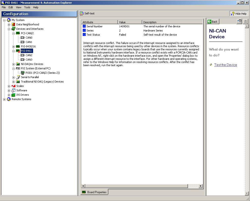
I'll put up a PXI module which, like a BOX of cards in a chassis PXI-1042 (PXI-8461) by using a controller PX-8360. I also have a PCI CAN map at the back of the PC that I use.
There seems to be a conflict - can someone help me please?
Concerning
Dave
PS I have recently updated to LabView2009 and also have installed 2.6.2 CAN
Hi all
DeltaJ came through a call to support with the same question. In the interest of everyone in the community, the problem has been resolved by simply moving around some of the modules in the chassis. Resource conflicts can often be solved this way.
Best wishes
-
NEITHER posted the following warnings earlier this year, but has not provided details about the symptoms of this block.
Possible system block with the third-party PXI Modules for some of PXI systems OR a 64-bit operating system
Notification of product: System Possible crash with the third-party PXI Modules
http://digital.NI.com/manuals.nsf/WebSearch/6C2BC403421708B5862579BF006E2D0B
This would produce a warning in LabVIEW, a pop-up window or a system crash? This error may occur in the background or only during the communication of the instrument? This would cause other LabVIEW, TestStand to hang or just PXI communication processes?
I don't want to take production systems down to an upgrade of the driver if it is not necessary. So I have the record of someone who has experienced this problem at first hand.
Thank you!!!
Sam Broyles
Test Engineer
INOVA geophysical
Sam,
If you start this problem, it is not subtle. It will stop what communication whether in the PXI chassis, including bluescreens or crashes the system (assuming that you use something in the chassis). It occurs whenever there is a 64-bit address bus, but when that happens, you will have a hard time missing.
-Robert
-
Choose specific channels to display indicators (DAQ)
Hello.
I have 4-way analog inputs connected with a (0, 1, 2 and 3) pxi module in a single task. I used a structure case for each of the input channels. I used the table to index for separate graphics and play them in a while loop. If I want to select channel 1 and 3, for example, the graphics are confused and they are displayed in the channels 0 and 1. Is there a way I can fix it channels to move in the right indicators?
Kind regards
StathPOl
Maybe you are looking for
-
I always use Firefox, but when I run CCleaner, Internet Explorer files appear... How? Why?
I never use Internet Explorer, always use Firefox, but when I run CCleaner, some files appear in Internet Explorer. Can't understand why?
-
Satellite 5100 503: engraving of a 800 MB CD
Hello Maximum capacity of a CD in the drive DVD/CD of the Satellite 5100 503 combo seems to be 703 MB. Is there a solution to burn CD 800 Mb / 90 minutes? Thank you
-
Version 4. Where the orange Firefox in the upper left tab?
After installing Firefox 4, I watched the tutorials. It is supposed to be a tab of orange color in the upper left corner of the browser - tab is called "Firefox". After installation, I found that I have no tab. Where is he? Is this necessary? I use X
-
The toolbar with Firefox parameters (0ptions, etc.) have disappeared. How to solve this problem?
Maybe it's a virus problem. Firefox no longer displays its toolbar, even after I download a new version. Only a black space appears where it used to be. I can't change the security or history or other settings. Any ideas how to solve this problem?
-
Fan runs continuously when open the mail
I have a new 15 "MacBook Pro retina, I have Aproblem with the fans running constantly. This only seems to happen when the mail is opened. If leaving the app e-mail the fan speed reduces and stops. When I open the application mail in seconds the fan s