XY plot
Hi, (I use LV 8.2.1)
I want to set the limits of a graph (like an image) to the size of the image that is bounded to the front.
(the user can change the size of the image).
I expect the VI attached to this message to do.
but for some reason, there is a mismatch between the limits of the limits of the graphic image.
Change the size of the image, and then run the vi and see that the size of the graphic is greater then the size of the image.
I would also like to add photos to the curve in different positions with regard to the graphical grid.
So I would like to find the transformation between the position in the image coordinates of the chart.
(I can add an image to a certain position in pixels, but I don't know the position of the grid of the graphic, in pixels,
Maybe it will be enough to get the position of the origin?)
Sincerely yours.
Amitai Abramson.
You're not counting the X scale in your dimensions. It could be argued that the screw that draw the graph are not to mention, if the programmer must do instead of this, but it's basically where it is.
Is there a reason that you are using the XY image as opposed to a standard XY Chart? You can always place photos (front, rear or middle) on the standard XY graph.
Tags: NI Software
Similar Questions
-
Is, mi Iphone 4S dejo funcionar el wifi from una las plots. El boton Quebec city lights el esta como auto wifi y no me permite encenderlo. Restableci las redes y el telefono pero the falla continued. Someone can help me? Gracias
Hello! Gracias por publicar in las Soporte communities of the Apple. Hemos lanzado una nueva Comunidad of Apple support in Spanish. If you interesa participar, registrate, encuentra una respuesta o publica una pregunta sober los productos y servicios of Apple that mas you interesen. Haz click in este enlacepara el sitio en Español visit.
-
Lopez Burk field (Double reciprocal plot)
Hi all
I'm doing a double reciprocal plot of my data of the enzyme. I don't know how to go from a basic scatter chart plot to a double reciprocal plot.
I got my macbook in 2014 and the software is: OS X 10.9.5 (13F1603)
Thank you much in advance.
Kind regards
J

Hello j,
Weber State University in Ogden, Utah, of a set of instruction has do a lot of Lopez Burk in MS Excel, that you can find here. Formulas to convert the data pairs are reversed, and the graph itself is a scatterplot with a linear trend line 'better to' added. Creating a table similar in number should be pretty simple by following the instructions in Excel.
Kind regards
Barry
-
Hi all
I'm doing a double reciprocal trace (Lopez Burk) for a study of the enzymatic activity. I've seen the plot on Excel but am not able to find
a similar solution in number. I tried to use the forecast function and also tried to get my bar tend to reach an estimate of values in my columns
in the negative numbers. No chance for many. How can I get the trendline to cross the y-axis? I don't know the technical steps to create a diagram.
I use numbers 3.6.1. and have a MacBook Pro from 2012.
Thanks for your help.
Kind regards
Jonelle

Maybe this will help you?

You can map all in simple X and Y, then get the best line made with a linear equation

-
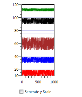
Separate ordered by plots makes data disrupted
Hello
In the attached draft, I have a check box that decide if the graph contains main axis or y-axis on each plot to exist.
in the image to follow, you can see the first screen with the data:
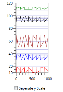
After that, I choose the separate box causing the disapear (because with 5 axes) chart - and it's OK for me.
It has problem when I unchecked the separate box, the troubled data. You can see in the following image:
This will be fixed when you move the chart by ctrl + left mouse.
Why is that happening and how can I fix?
Finally, I solved the problem in the following way:
I subscribe to plot the area SizeChanged event, and when the size is largest of the previous size & the previous size was smallest of spesific width (which means that the screen was small and now it is grown), I call Refresh.
' Private Sub PlotArea_SizeChanged (ByVal sender As Object, e SizeChangedEventArgs)

{

   < 80="" &&="" e.newsize.width="">e.PreviousSize.Width)

      Application.Current.Dispatcher.BeginInvoke (new System.Action (Refresh), System.Windows.Threading.DispatcherPriority.ContextIdle);

}
I change the priority of ContextIdle because when I opened the window to reflect the priority charge does not help, and in this case, I need low priority.
-
Graphic with several plots, a cursor jumps by programming of intrigue to tlot
Hello
I use MS 2013 with Vstudio 2010
I have a graph with 3 plots, and a slider that at design time is attached to trace 0.
I need to attach this cursor on plots of 1 or 2, according to the index of my choice.
I guess that a solution would be to remove the existing gursor and re - create a new, attached to a different field.
But can it be done using the existing slider? I couldn't find a way to do it.
I need something like:
' private void comboBoxCursor_SelectedIndexChanged (object sender, EventArgs e)
{
var selected_plot = comboBoxCursor.SelectedIndex;
var cur_indx = waveformGraphScope.Cursors.IndexOf (xyCursorScope);
waveformGraphScope.Cursors.?. Plot [selected_plot]
}Thank you
Igor
In fact, it's simple:
If "selected_ch" is a parcel number, then he focus cursor to a particular field:
waveformGraph.Cursors [0]. Plot = waveformGraph.Plots [selected_ch];
Igor
-
"print" command in Mathscript recording is not the plots in BMP format!
Hi guys,.
I am creating a vi that automatically generates a pdf for my project report. I found a way to record the report directly in pdf format (in other words, I have 'print' my report to a (PDFCreator) Virtual PDF printer that saves the file in a specific folder with the date/time under his name.) "So, this was the first step to make the automatic procedure).
I'm stuck in the next step, which is adding to the report no graphics bad appearance of labview, but the plots of the victims of the Mathscript.
Yes, after you have added as input 'a' my data to the mathscript node, I use the following commands:
Figure
Plot (a)
print the image
Now, what is this sequence is to do a beautiful land of my data and then save it as "image.eps" in the default folder.
However, the eps format is not at all useful to me because I can't import the plot with the 'Add Image to Report.vi '. This vi supports the formats BMP, GIF, WMF, EMF and JPG only.
So, I want to save as BMP mathscript plot. It's supposed to be possible, but I have not been able to find a way. Using the command 'Print' for Labview Mathscript 2011 reads as follows:
http://zone.NI.com/reference/en-XX/help/373123B-01/lvtextmath/msfunc_print/
Syntax
print
Print (a)
Print (file)
printing (, file)
Description
Print the trace window, or save it in a file in BMP or EPS format. If the trace to save window is a plot of the image or a 3D terrain, the file must be in BMP format. Other types of plots, formats BMP and EPS are supported.
There is no way for me to choose what format I want, and it automatically selects the eps. If I use the command
print image.bmp
It gives me an error. So adding the endpoint .bmp is not the way to go.
Overall, it is essential for me to export the plot in BMP format (in order to import it into the generation of report), but I can't find a way, althouth it is supposed to work.
Any ideas?
Thank you
PS. I run Labview 2011 SP1
Hello
You must use the following command
Print ('test.bmp')Instead of
print test.bmp
-
Build the table to 2 dimensions to plot a graph from UIMessages
Hello guys,.
I need some advice, the problem I have is that I want to pass an array [0 5] numbers to my throwugh of custom UI UIMessage to plot a graph with these data in the same grapgh (see the behavior of the 6 signals on the same graph), but so far I could only pass a value and see only a signal in the graph.
Is there a way to pass the french table UIMessage using the activeXDataParam? Or may be otherwise?
Thanks for your comments.
Eder
I threw together a simple example in TS 2014 and 2014 LV. I think it does what you want. Simply run the main vi in the project and select the random sequence file Array.
In addition, attached is a photo of my UserMessage vi.
Hope this helps,
-
Graph plot legend colors Signal not updated when mixed with the property node
Hello
We try to put the colors of the trace of a graph of Mixed Signal using a property node. Although we can change the color of the data in the field correctly, the colours of the plot in the legend do not change until some apparently unrelated operator action is performed (for example, to resize the window or by double-clicking a field name). Waveform to XY charts don't seem to have this problem.
Anyone know a work around? I think I saw a similar topic on the forums earlier, but I'm sorry that I am unable to find it now

See attached vi.
Thank you
-john
I should probably have joined the last post of VI, but I have has been a thread of error between the two loops. I also deleted the text you had so I could see the I need to press the button.
-
Hello
I have 2 data in Labview, we're a couple time and Temperatura x time x. I want to put this in a report in a way I'm havo two pieces of information in the same chart, but without going through the plot. My idea is to make the bones of color temperature curve x acodding time change to the value of the couple at the same time. So when the torque curve will be red and when the couple is low the curve will be gree, and between the maximum and minimum values, I have a range of colours...
What is an easy way to do it?
Thnx
Hi Marcus,
You must double-click the 3D graph and check the legend box in the lower left corner of the dialog box to display the legend. After that, you can click on the 'Settings' button to the right of the "Legend" box to change the appearance of the legend.
Brad Turpin
Tiara Product Support Engineer
National Instruments
-
angles, positive and negative area on a plot of polar
Is there a way to label the sector on a polar plot angles with +/-values? We generate a lot of bosses of directivity of sonar and angles scored from-180 to 180 instead of 0 to 360 have long been the norm. Looking at the definition of the curve and Polar - display the tab - it doesn't seem to be an obvious way to do it.
Hi Greg,.
Unfortunately, there is no way to do in tiara at the moment. I presented a report of Corrective Action to resolve this (#323394), and I hope that this feature will be included in a future version of DIAdem. Thank you for that bring to our attention.
Kind regards
Jackie
-
I have a graph of waveform with two parcels and a cursor with = NearestPoint SnapMode.
When you remove the plot that the cursor is currently pointing, I want to associate the slider with another plot.
For this love, I subscribed to the the cursor PropertyChanged event. When the plot of the cursor change, I expect to be drawn from this event. In the handler, I agree with the Disposed of the new plot event. In the Manager has, I point the cursor to another plot.
The problem with this approach is that the PropertyChanged event is not raised when the cursor is moved from one parcel to another plot.
Although there are several ways to work around this problem, this behavior is unexpected. I expect a PropertyChanged to be triggered whenever the plot of the cursor property changes.
Reproduced with version 2010 SP1 (9.1.0.204)
Seems that they have made some changes in 2013 MS, see 384987. Thank you for the study.
I'll look into it when you upgrade.
-
WPF graphics, display plot marker (with contact information tooltip) on the mouse event
Hello
I need display the coordinates of the point of the field when the mouse pointer is positioned top/close to him.
I already display a ToolTip with coordinates using the code in this LINK (works equally well for graph).
However, it is not easy to see where the field is selected, especially when you have more than one land close to eachother. Is there a way to display some sort of a 'marker '? A bit of as Signal Analyzer?
Thank you.
If you want to display a target and the label next to the value as a user moves the mouse over a graphic, a possibility would be to use
SetRelativePositionon a slider.If you want to just use a marker in the chart and keep the label in the ToolTip, you can set the relative position of a Visual in the
Childrencollection:XAML
ni:Cursor x:Name="cursor" />
Ellipse x:Name="marker" Width="10" Height="10"
Stroke="Black" StrokeThickness="2"
niPrimitives:RelativePanel.RelativeHorizontalAlignment="Center"
niPrimitives:RelativePanel.RelativeVerticalAlignment="Center"
/>
Code
private void OnPlotAreaMouseMove( object sender, MouseEventArgs e ) {
IPlot plot = graph.AllPlots[0];
Point screenPosition = graph.GetPlotAreaPosition( e );
Point relativePosition = graph.ScreenToRelative( screenPosition );// Option 1
cursor.SetRelativePosition( relativePosition );// Option 2
PlotValue nearestValue = graph.FindNearestValue( plot, relativePosition, query );
if( nearestValue != null ) {
graph.ToolTip = string.Format(
"Nearest value is at ({0},{1}).",
nearestValue.Value.CastPoint nearestValuePosition = nearestValue.GetRelativePosition( );
RelativePanel.SetRelativeHorizontalPosition( marker, nearestValuePosition.X );
RelativePanel.SetRelativeVerticalPosition( marker, nearestValuePosition.Y );
}
} -
Cannot zoom plot unless I have add another parcel "dummy".
I have a weird situation...
I add programmatically to the plots in my nor: graph (c#)
ChartCollection
Plot = new Plot (label);
parcel of land. Renderer = new LinePlotRenderer() {Stroke = brush, StrokeThickness = 0.5};
Graph Data.Add (chartCollection);
Graph Plots.Add (plot);.....
chartCollection.Append (Initializer.DictionaryOfAllPossibleFrequencySteps [frequencyStep] .frequencyVal, realVal);Everything works fine except when I try to zoom by using GraphInteractionPalette, the LATEST added intrigue remains static, while everything else is zoom.
For some reason if I add a "dummy" (with no data) when I'm done adding actual locations, all well zoomed in... including the last plot. It's almost like the last parcel is not be 'active' or something. Am I missing some appeal?
Thank you.
I just wanted you to know that this (#476665) problem has been fixed in the version of Measurement Studio 2015 .
-
Graph: graph of WPF. Error Plots.Clear)
Hello
I need dynamically add patches to the chart. Code like this,
ObservableCollection
Graph DataSource = dataSource;
public void AddOnePlot (Point [] pointData)
{
Plot = new Plot();
Graph Plots.Add (plot);
dataSource.Add (pointData);
}
But when I call graph. Plots.Clear: the error is "beach action are not supported.". How to erase all the plots in the graph?
Looking forward to your response. Thank you.
The
Plotscollection on theGraphclass derived fromNotifyingCollection, which raises a single optimized global event when several items change. On the other hand raises theObservableCollection.NET separate events for each item in the collection. Measurement Studio controls are supported on both models, but the WPF controls such asItemsControldo not support aggregation events ("actions range" in the error message).However, there is a bug in the current version of the
Legendcontrol: If you bind theItemsSourceproperty to a collection rather than a chart, you may encounter this error if a default collection view is created. To avoid this, you can serialize events (as you demonstrated above, removing individual items instead of compensation), or you can use theNotifyCollectionChangedSimplifierto adapt the collection for the model "a separate event for each item:xmlns:ni="http://schemas.ni.com/controls/2009/xaml/presentation"
xmlns:niPrimitives="http://schemas.ni.com/controls/2009/xaml/presentation/primitives"...
... -
Hi guys,.
I've been using Diadem only 1 month and I got answers a lot of this forum earlier. This question may seem trivial, but could someone tell me how to plot a channel by writing a script. So far, I have this:
View.Sheets ("sheet 1"). Cursor.Mode = "GraphPoints".The only way I found to import a channel in this area is to call interactioOn(), import it manually then put an end to the interaction. I want to do it manually, I tried this but it would give errors:
View.Sheets ("sheet 1"). Areas ("area: 1"). DisplayObj.Curves.Add (1.3)Can someone give me a hand?
Thank you
Hi Leillo,
Try this.
Call View.LoadLayout ("view3")

Set the sheet = View.Sheets (1)

Set area = Sheet.Areas (1)

Area.DisplayObjType = "CurveChart2D".

Graph of the value = Area.DisplayObj

Call Graph.Curves.RemoveAll

Curve value = Graph.Curves.Add (XChannelRef, YChannelRef)
Brad Turpin
Tiara Product Support Engineer
National Instruments


Maybe you are looking for
-
It is possible to activate the option "Highlight the whole line" on and off during execution in a multicolumn listbox? I know that the option is available in the right click of the FP control menu, but I was wondering if this can also be done program
-
Error 800705AA during the upgrade to Windows 10 via Windows Update tool
I have my old HP laptop with preinstalled WIndows 7 32 bit. Some time ago, I decided to install Linux alongside Windows, so I deleted the partition that allows you to reinstall the operating system (don't ask my why I deleted it instead of parition H
-
Hi Experts, We have a project consisting of AV systems with control using Crestron system and videoconferencing system using SX80 codec. The plan is to all the controls will be done using the Crestron with its touchscreen for centralized control syst
-
Hi all I had a question about the assessment of DAP & endpoint. We are looking to replace our Pix with ASAs. One of the conditions will be a remote VPN access. We have about 25 people with the company issued laptops that need the ability to VPN in. W
-
We have a MX200 which lies outside our firewall outside parties can call the MX200. It is a new system and since I installed it first, I noticed that after a day or two, I saw a lot of calls missed the newspaper calls. I don't know whether or not t