2960S stack Member priorities
I have sought a clear answer as to what defines a 'priority' on the stack members.
Documentation of configuration of the battery and election of master reading, it is clear to me if a lesser number integer or integer greater is a higher priority. More simply put, 1 the highest priority, or 15 the highest priority possible?
Priority member values
A high priority for a member value increases the chances that he will be elected master and keep his membership number. The priority value can be from 1 to 15. The default priority value is 1.
Reading through the documentation for stack configuration and master election, It is unclear to me if a lesser integer or greater integer constitutes a higher priority.
'15' priority is the highest value or priority. A switch with a priority of the battery of the '15' doesn't mean 'no election '.
Tags: Cisco Network
Similar Questions
-
2960S - no connectivity to interface fa0 mgmgt?
Hi people,
I'll try to make this short!
I have a pair of 2960S stacked (LAN basic WS-C2960S-48TS-L to be exact) toggle 12.2 running (58) SE2 configured with multiple VLANs. No of them have VLAN interfaces active L3 and the switch can therefore be managed by the management port fa0 (via https/ssh) and the console.
The problem I have is the fa0 connectivity fails, depending on where I'm ping of. For example:
Port 2960 (fa0) MGMGT--> switch upstream<-- 2960's="" vlan="" 100="" (gi1/0/26)=""><-- client="">
|
|
Rest of LAN
Pings to fa0 LAN or switch upstream - PASS
Pings to fa0 VLAN100 customers - FAIL
Pings to rest of LAN of VLAN 100 customer - PASS
Lets say we extend the above as follows:
Port 2960 (fa0) MGMGT--> switch upstream<-- 2960_vlan_100="" (gi1/0/26)="" |="" 2960_vlan_100="" (gi1/0/28)=""><-- downstream="" switch=""><-- dsktp="">
|
|
Rest of LAN
Same results as the initial installation, but additionally:
Pings to fa0 customer switch downstream - FAIL
Pings to rest of LAN switch/clients downstream - PASS
So I think that what is happening is that the 2960 detects fa0 MAC resolves to one of its own interface addresses and therefore do not pass traffic on the switch upstream. The end result is that the traffic never reaches fa0. Could someone please confirm if my reasoning is correct here? And is it possible around this installation problem?
I have attached my configs in a zip if it helps.
Thank you very much
Alistair
EDIT: I would also add that the ARP entries for fa0 are present and correct in the ARP tables to downstream customers.
Edit2: Added 'loopback' command to fa0 with no luck and downloaded Windows EOL RC
Hey, Alistair,.
I believe that the best route to effective management would be to assign an IP address accessible to an available LAN VIRTUAL interface, configure your settings vty and disable Fa0. If security is an issue, you can always also set specific security settings.
Hope this suggestion helped!
Thank you
Mikey
-
Hello
Before you start left exercise me the by official "help I'm not a network guy" sentence!
I just bought 2 x N2048 L2 switch with stacking cables. I need to configure these to work with an existing pile of L3 PC 6224. 6224 battery has 2 x 10GB sfp module links and is configured as an access and management with all VLAN resulted them in a firewall.
the order of for the States of N2048 (not stacking inter series) stacking is very different between these 2 switches is not surprising - so it seems I should these LAG? -What would look like this?
Thank you and all my apologies if this is very blurry
Rob.
Hi, Rob!
The LAG (aggregation of links) is simply two or more cables of connection between two network devices. A single cable connection can also work, but using several cables can provide higher availability (backup in case where a cable/port breaks down) and higher bandwidth. GAL (also known as the Group of channels or channels of port) can be created through 2 or more ports of the switches of members different battery.
In your case, it seems that you want to move forward and to stack your switches N2000 using cables stacking that came with them. Once this is done, you can use two or more cables to connect the two batteries. Each stack will look like a single switch to any other network device that connects to it. Each of your stacks think so in this case, that it only connects to another switch even if it is actually connected to another battery (multiple switches).
For high availability, plug a cable in a stack member (any port) and the second into a second member of the same stack stack (any port) is the best practice. Do the same for the other battery when connecting the two batteries. In this way, if a member breaks down, connectivitiy between two batteries will stay up. This example is just using an OFFSET of 2-port, but the same thing could be done if you use more ports.
B
-
Hello
I'm trying to get our network out of a topology of flat to work with the hardware I have on the spot I have setup the network and local networks virtual, but could not get any other VLAN to carry. Here is what I use:
Reference Dell PowerConnect 6248 as my router from Layer 3 and three PowerConnect 2748 detach the 6248 in three GAL groups all with four ports together. I have VLAN 10-50 for various average things regime 192.168.10.0/24, 192.168.20.0/24, 192.168.30.0/24 ect.
Here's the question: 10.0 network works fine, but on any other VLAN, I get an IP address from the DHCP server, but I can't ping my gateway let alone ping another VLAN.
Heres my living room will be output:
console#show run

    !Current Configuration:

    !System Description "PowerConnect 6248, 3.3.11.2, VxWorks 6.5"

    !System Software Version 3.3.11.2

    !Cut-through mode is configured as disabled

    !

    configure

    vlan database

    vlan 5,10,20,30,40,50

    vlan routing 20 1

    vlan routing 30 2

    vlan routing 40 3

    vlan routing 50 4

    vlan routing 1 5

    vlan routing 10 6

    exit

    stack

    member 1 2

    exit

    ip address 192.168.6.6 255.255.255.0

    ip default-gateway 192.168.6.1

    ip address vlan 5

    ip routing

    ip route 0.0.0.0 0.0.0.0 192.168.1.1

    interface vlan 1

    routing

    ip address 192.168.1.2 255.255.255.0

    exit

    interface vlan 10

    name "Servers"

    routing

    ip address 192.168.10.1 255.255.255.0

    bandwidth 10000

    ip mtu 1500

    exit

    interface vlan 20

    name "Production"

    routing

    ip address 192.168.20.1 255.255.255.0

    ip helper-address 192.168.10.110

    exit

    interface vlan 30

    name "WD Staff"

    routing

    ip address 192.168.30.1 255.255.255.0

    exit

    interface vlan 40

    name "Non WD Offices"

    routing

    ip address 192.168.40.1 255.255.255.0

    exit

    interface vlan 50

    name "Church"

    routing

    ip address 192.168.50.1 255.255.255.0

    exit

    username "misterp" password beda28c8e29f04603da19eb1b3b239ee level 15 encrypted

    !

    dhcp l2relay vlan 20

    dhcp l2relay circuit-id vlan 20

    dhcp l2relay remote-id 1 vlan 10

    dhcp l2relay remote-id 20 vlan 20

    !

    interface ethernet 1/g1

    switchport access vlan 10

    exit

    !

    interface ethernet 1/g2

    spanning-tree portfast

    switchport mode general

    switchport general allowed vlan add 20,30,40,50 tagged

    exit

    !

    interface ethernet 1/g3

    channel-group 1 mode on

    exit

    !

    interface ethernet 1/g4

    channel-group 1 mode on

    exit

    !

    interface ethernet 1/g5

    channel-group 1 mode on

    exit

    !

    interface ethernet 1/g6

    channel-group 1 mode on

    exit

    !

    interface ethernet 1/g7

    channel-group 2 mode on

    exit

    !

    interface ethernet 1/g8

    channel-group 2 mode on

    exit

    !

    interface ethernet 1/g9

    channel-group 2 mode on

    exit

    !

    interface ethernet 1/g10

    channel-group 2 mode on

    exit

    !

    interface ethernet 1/g11

    channel-group 3 mode on

    exit

    !

    interface ethernet 1/g12

    channel-group 3 mode on

    exit

    !

    interface ethernet 1/g13

    channel-group 3 mode on

    exit

    !

    interface ethernet 1/g14

    channel-group 3 mode on

    exit

    !

    interface ethernet 1/g15

    switchport mode trunk

    switchport trunk allowed vlan add 10,20,30

    exit

    !

    interface ethernet 1/g16

    switchport access vlan 10

    exit

    !

    interface ethernet 1/g17

    switchport access vlan 10

    exit

    !

    interface ethernet 1/g18

    switchport access vlan 10

    exit

    !

    interface ethernet 1/g19

    switchport access vlan 10

    exit

    !

    interface ethernet 1/g20

    switchport access vlan 10

    exit

    !

    interface ethernet 1/g21

    switchport access vlan 10

    exit

    !

    interface ethernet 1/g22

    switchport access vlan 10

    exit

    !

    interface ethernet 1/g23

    switchport access vlan 10

    exit

    !

    interface ethernet 1/g24

    switchport access vlan 10

    exit

    !

    interface ethernet 1/g25

    switchport access vlan 10

    exit

    !

    interface ethernet 1/g26

    switchport access vlan 10

    exit

    !

    interface ethernet 1/g27

    switchport access vlan 10

    exit

    !

    interface ethernet 1/g28

    switchport access vlan 10

    exit

    !

    interface ethernet 1/g29

    switchport access vlan 10

    exit

    !

    interface ethernet 1/g30

    switchport access vlan 10

    exit

    !

    interface ethernet 1/g31

    switchport access vlan 10

    exit

    !

    interface ethernet 1/g32

    switchport access vlan 10

    exit

    !

    interface ethernet 1/g33

    switchport access vlan 10

    exit

    !

    interface ethernet 1/g34

    switchport access vlan 10

    exit

    !

    interface ethernet 1/g35

    switchport access vlan 10

    exit

    !

    interface ethernet 1/g36

    switchport access vlan 10

    exit

    !

    interface ethernet 1/g37

    switchport access vlan 10

    exit

    !

    interface ethernet 1/g38

    switchport access vlan 10

    exit

    !

    interface ethernet 1/g39

    switchport access vlan 10

    exit

    !

    interface ethernet 1/g40

    switchport access vlan 10

    exit

    !

    interface ethernet 1/g41

    switchport access vlan 10

    exit

    !

    interface ethernet 1/g42

    switchport access vlan 10

    exit

    !

    interface ethernet 1/g43

    switchport access vlan 10

    exit

    !

    interface ethernet 1/g44

    switchport access vlan 10

    exit

    !

    interface ethernet 1/g45

    switchport access vlan 10

    exit

    !

    interface ethernet 1/g46

    switchport access vlan 10

    exit

    !

    interface ethernet 1/g47

    switchport access vlan 10

    exit

    !

    interface ethernet 1/g48

    switchport access vlan 10

    exit

    !

    interface port-channel 1

    spanning-tree disable

    spanning-tree mst 0 external-cost 5000

    switchport mode general

    switchport general pvid 10

    switchport general allowed vlan add 10

    switchport general allowed vlan add 20,30,40,50 tagged

    switchport general allowed vlan remove 1

    exit

    !

    interface port-channel 2

    spanning-tree disable

    spanning-tree mst 0 external-cost 5000

    switchport mode general

    switchport general pvid 20

    switchport general allowed vlan add 10

    switchport general allowed vlan add 20,30,40,50 tagged

    switchport general allowed vlan remove 1

    exit

    !

    interface port-channel 3

    spanning-tree disable

    spanning-tree mst 0 external-cost 5000

    switchport mode general

    switchport general pvid 10

    switchport general allowed vlan add 10

    switchport general allowed vlan add 20,30,40,50 tagged

    switchport general allowed vlan remove 1

    exit

    exit
As a side note, I don't have really messed with other VLAN only 20.
Any help would be great. I'm just puzzled.
Thanks Daniel, I understand this problem. on the 27xx series switches I was marking traffic on clients without realizing it was not labeled. New network equipment in collaboration with a Cisco and DELL all this background I've ever had to deal with THIS a marking was done automatically.
-
Replace the battery. Reference Dell 6248
Hello!
We have a set of three Dell Powerconnect 6248 switches.
One of the switches must be replaced with the new one (same model).
the well known "pwcnt_stacking_switches.pdf" document does not say how to replace a member of the battery,
just how to add additional, or to remove switch a.
It is said in the documentation for the 3524 powerconnect switches:
Exchange of stacking of members
If a member of the stack with the same unit ID replaces an existing UnitID with the same ID of the unit, the
the previous device configuration is applied to the inserted stack MemberEven apply to 6248? This approach works?
How a stand-alone switch can be prepared to be added to the stack as some number of particular unit (excluding implementation stack-port mode battery)?
is it
Renumber (conf) #switch
?
Yes, guess I replace unit Number or number 2. (out of three)
Once I have remove the old unit 2 and insert a new one, the new switch will get UnitID = 4.
After I using renumber
switch 4 renumber 2
He will get all the previously attributed to the old switch 2 port configuration?
-
2960 - S FlexStack - stack integration issue?
I have a client with two features of WS-C2960S-24PD-L, both devices have Flexstack modules and run a software C2960S (C2960S-UNIVERSALK9-M), Version 12.2 (55) SE2, VERSION of the IOS SOFTWARE (fc1).
The first switch is for use with a running-config on it and because of migration the customer asks me to add the new switch to the existing switch to make a single stack (CoXYZStack).
I dug around on Cisco's Web site and am not able to find the following Guide Flexstack;
http://www.Cisco.com/en/us/prod/collateral/switches/ps5718/ps6406/white_paper_c11-578928.html
Unfortunately, this document is not really detail the configuration that I need a switch? Someone got the configuration Cisco Flexstack experience, if so can you give me some advice on the system requirements on the two switches.
Basically what is happening, is that both switches act as independent 'stacks' in their own name and I am unable to get them to recognize each other or operate together in one set.
1 supply ws-c2960s-24pd-l switch
switch 2 supply ws-c2960s-24pd-lI tried the 'x' provision "xyz" switch line configuration on CoXYZSw1, and as you can see when you do a 'detail of switch sho' it shows as provisioned but on the CoXYZSw2 nothing ports battery or battery come off the power ring?
CoXYZSw1 #sho switch retail
Switch/battery Mac address: c8ba.bf77.1234
Current H/W
Switch # Mac address priority Version State role
----------------------------------------------------------
* 1 master c8ba.bf77.1234 14 1 Ready< you="" will="" see="" i="" also="" tried="" altering="" coxyzsw1="" priority="" to="" 14="" to="" ensure="" it="" came="" up="" as="">
2 Member 0000.0000.0000 0 1 put into serviceCoXYZSw1 #sho switch stack-ring speed
Speed ring battery: 10G
Configuration of the stack ring: down
The ring protocol stack: FlexStackCoXYZSw1 battery-ports of the switch #sho
# Port 1 Port 2 Switch
-------- ------ ------
1 down DownAnd as you know the switch does not see or recognize his neighbor? I tried the two possible Flexstack wiring configuratione i.e. battery 1 battery 1 / Stack 2 to 2 and 1 battery battery battery 2 / 1 battery battery 2
CoXYZSw1 #sho neighboring switch
# Port 1 Port 2 Switch
-------- ------ ------
1 none noneAnyone has any ideas or a configuration example would be greatly appreciated.
PS: Also had a trial with this config "stackmaker", but that doesn't seem to help much either? "stackmaker name CoXYZStack.
You need a minimum of a battery cable is connected.
Make sure that the 2nd switch DO NOT HAVE any configuration in there.
And Yes, turn off the switch member of battery 2, connect a cable from the console and it lights up. After the generated output.
-
SPF % SFF8472-5-THRESHOLD_VIOLATION: WE stack 2960 X swtich
Hi all.
We install a 4x2960X new switches. of master swtich to the basic link. shows the battery captain
% SFF8472-5-THRESHOLD_VIOLATION: item in gi1/0/50: low power warning Rx; Running value:-20,3 dBm, threshold value:-17,0 dBm.
FPS is a cisco SFP and the version of the stack is c2960x-universalk9 - mz.150 - 2A .ex5 .bin.
could some please explain what is this way to journal.
Hello
That is right. The message does not damage anything.
HTH
-
Hey Cisco,
I think that I'm not the only one facing this issue when run command reload
I tested x 2960 as version below
normal run charging for Member or another switch of type charging slot 2, it works very well by charging slo type 2
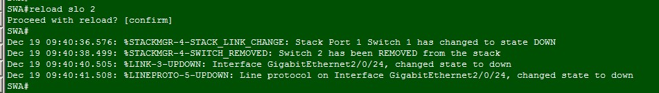
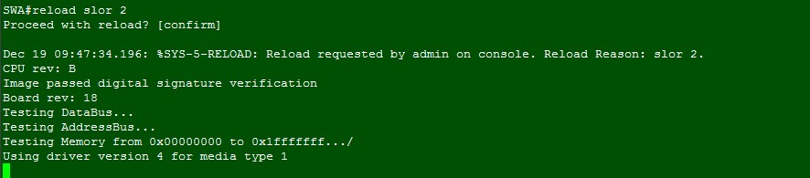
When I switch to reload CSL 2, typo invites me error, but seeking to confirm it; In this kind of situation, I just press on enter because I guess I type correctly
Surprise, it reload the entire stack switch
so I test it with the version recommend
same question comes, it recharges battery set switch
If typo recharge slotx 2, it always reload the entire stack
Please consider this question
Hi Vui,
The behavior you are observing should because you do not use the correct syntax in order to recharge the required slot.
The correct command is as follows, please note the keyword exact "slot:
SWA#reload slot 2
By typing "charge CSL 2", you say the battery to recharge all members for the reason "CSL 2" which is used management and logging. Please see the following link for more details about this command: http://www.cisco.com/c/en/us/td/docs/switches/lan/catalyst2960x/software/15-0_2_EX/stack_manager/command_reference/b_stck_152ex_2960-x_cr/b_stck_152ex_2960-x_cr_chapter_01.html#wp3486313748 -
Port Mirroring a LAG on stacked Dell PowerConnect 6248 s
Hello
It is possible to port mirror use as a source, a SHIFT, consisting of 4 ports (2 in each Member of a set of 6248 s PowerConnect stacked). Whenever I'm trying to add the source, using GUI, I get an error:
Error! There not together "Type" with "Tx and Rx" error occurred in FILTER_MISSING
This allusion is what filter?
I can't select a spring, unit 1 or unit 2, members of the LAG, like the gui only shows them not from the ports drop.
Thank you.
Unfortunately, the switch is able to mirror individual ports as source ports. You can check this by trials of establishing a mirror session where the source port is not part of a LAG.
-
Adding to connect 6224 replacement for stacking
Hello
We just had a power connect 6224 replaced under warranty.
-J' removed the stacking of the faulty switch module and installed in the new switch.
-Power switch replacement and active stacking ports
-Saved config, power off
-Attached to the other switch in the stack with stacking cables
-Powering new switch
-Master restarted
-Circuit breaker is backup and running normally, however the Member switch shows "code incompatibility?
I tried to turn off the Member, remove the Member from the stack, and then restore power (I can not reset the master only outside the hours). But I still get the same code shift.
Any suggestions?
Looks like the firmware is not the same. Use the command > view version, to see what firmware the switches are on. The replacement switch must be on the same firmware as the pile. If they do not match, now may be a good time to get them all to date.
Tell us what you find.
-
Im doing sort of a proof of concept, and I just want to make sure that this will even work on these switches, because I'm not finding a path in the web interface that makes it look as if it was possible...
I would like 2 switches on both ends of a connection of the battery and then use a copper and fiber run to a SHIFT to battery. Ideally, I'd put fiber as part of a battery and the copper in the other Member of the stack. This way if I lose a member, I always one connection through the other.
Best as I can tell, the ports of battery works very well in that I can get a master light on one and one ID on the other. But I'm not sure I see how to specify in the stack, the LAG exists in a way such that it is on each of the switches.
But with the LAGGY menus, it looks like im only able to specify the ports 1-8 and no ports G.
I'm too complicate this and missed something simple or and I just totally out of the way?
Well apparently my just stacking was not not display correctly... I made a start of led and was able to successfully achieve my pile of numbering.
After that, the interface switch stacked came on menus LAG and I was able to set the time to wait/priority/etc very well.
-
I have 2 stacked N2048P switches. Shortly after the deployment, I started to have constantly the errors below:
DRIVER 172.x.1.x - 2 [108576100]: broad_hpc_drv.c (4362) 8073 %% unit: 0
CDC RX FIFO error table entry 0 39 ECCDRIVER 172.x.1.x - 2 [108576100]: broad_hpc_drv.c (4362) 8121 %% unit: 0
CDC RX FIFO entry error 37 double-bit ECCHere are the nine switches configured by Dell. I'm not familiar enough with the operating system to solve problems. Everyone knows this? If so, how to solve it?
Hi chanjohn01,
The error is a memory error. You can try to update or Flash the image and see if that helps. http://www.Dell.com/support/home/us/en/19/drivers/DriversDetails?driverId=Y7V3N&FILEID=3376784553&osCode=NAA&ProductCode=networking-N2000-Series&LanguageCode=en&CategoryID=NI
If this does not resolve the problem, try unstacking and ensuring that it is just the first member of battery that is giving the issue, the error refers to unit 0.
-
Dell PowerConnect 7048 P reference stack Questions
Hello
I have two switches in L3 7048P I want the battery but I'm not sure how it works. The two switches have the same firmware.
1 must. the two have the same configuration running on both to make it work?
2. in addition, I created a VLAN (3) voice on the first switch with an IP address of 10.0.3.254. I use the same IP address on the second switch in the VLAN 3 addresses or assign another?
Thank you!
There is a guide especially for stacking switch 7048 on the Dell page networking white papers:
en.Community.Dell.com/.../2580.Networking-guides.aspx
Just search "Dell PowerConnect 7000 Series Switches stacking". Page 16 will tell you how to add a new Member to the battery with minimum interruptions. Both can present the same firmware in order to stack. So the answer to question 1 is no, the configurations do not need correspond to stack them. Once stacked, both will look like a single switch, and you use only the IP address of the master swtich to the whole stack. Therefore, treat the two switches as a single switch during Setup. The guide provides more information on how it works.
Hope this has been helpful.
-Victor
-
Member of the main force in a pile of N2000
Hello
I have a stack of switches N2000. For fair and easy management I want to force the master to a particular switch do not rely on higher MAC or other options in the manual.
Is my question, possible to force a master member into a pile of N2000/N4000? (I read on the failover standby and initiate force, but it is not a good enough solution for me).
Kind regards
Hello
I confirm, renumber ID does not affect the election of master. There is no way to force the election of master.
In any case, becomes the ID is just enough to switch identification which was my goal prymary.
Kind regards
-
I am brand new to PowerConnect switches, even though I am familiar with the concepts of VLANS, aggregation of links and spanning tree.
I am on a deadline to get some new ones installed 6248 in our baskets and get them functioning as a stack. What are the bare minimum commands for:
- Three switches in a stack (master/Eve/member)
- 2 ports grouped between each (total redundancy) switch with loops WITHOUT switching
All the switches are running firmware v3.3.9.1 (January 2014).
Thank you
The range of interface Ethernet 1/g1-1 / g2 allows you to select the ports you want in the channel of the port. Page 293
Channel-group 1 Auto mode to create 440 lacp lag page
Select the Group of channels with interface port-channel 1
Switchport page 601 in trunk mode
Switchport trunk allowed vlan [VLAN you use]


Maybe you are looking for
-
On the "management of bookmarks.
You provide all the functions that can allow me to create a "bookmarks folder" which collects similar bookmarks?
-
Re: Crash on Tecra M3 of screen
This morning my Tecra M3 green screen LCD turned and then slowly disappeared in a cloudy cloud.When I restarted I had a large screen with red and white rays online and weird graphics. Windows XP logo comes up but is covered with white lines vertical
-
Equivalent DAQmx claims NIDAQ orders
Then I start to excavate in the VB6 code that has been written about 8 years ago by one of my engineering students. Best I can tell, some of the first calls the NIDAQ functions are: INIT_DA_BRDS() AO_VWRITE() Basically, he checked to see if the stat
-
A few months ago my mousepad stopped working for no. (obviously there must be one) reason. I noticed it after that I started to share music with other computers on our network. At first, I thought that the red light was something to do with it, then
-
Impossible to run a program as an administrator
I have windows 7, I try to run a program and it know the I did not have high enough privileges to run the program, I have to be an administrator. I am an administrator on this computer. I did prompt net user administrator / Active: Yes and log in a