6259
Hello
I am currently using the connected to a block TBX-68 and Labview 2010 6259. Basically, I'm trying to just use it for a multimeter to get accurate and timely measures, but there is something I don't understand all the examples in Labview.
My program is set up very similar to the "Acq a Sample.vi." I use a wizard DAQ with CSR configuration. When I connect a voltage source to a resistance that is connected to the PIN 68 to the TBX and spindle 67 to the land of the source voltage and the current measurement, I get a reading, however the current changes only as a source of voltage is changed. If I trade on the strength of a higher (or lower) value, the current does not change. I think it has something to do with the resistance of internal shunt within the program, but if I need to measure current with precision to determine an unknown resistance, how can I do this?
Mayy_B,
First of all, you should not use CSR to your measure, you should use NRSE because you don't measure a floating source. More information can be found in this article: http://www.ni.com/white-paper/3344/en
Please note that this will change the wiring on the TBX-68 block and require the negative line go to pin 62. In addition, there is no internal resistance in the 6259, an external shunt resistance must be used. This resistance must be connected between pins 68 and 62. You specify the value of the resistance in the DAQmx create virtual channel vi which is put in place for the current task of Analog Input. This should lead to a current measurement precise.
Tags: NI Hardware
Similar Questions
-
Detection of pulse NI 6259 photon counter min
Hello
I have a PCI 6259 DAQ card which I use as a counter. Is there a limit to the minimum pulse width it can count all operating as a counter? My meter of photons gives the TTL pulses with widths of 50ns which I think is less than what the meter may read unless I'm mistaken. I use 100 kHz as the clock source internal clock. Is there anyway to get the counter to pick up these small impulses?
The NI PCI 6120 DAQ card would be a better choice for this kind of measure? I should be able to get my hands on a bit of time.
Thanks for your time,
Select this option.
Well I just learn something new, I didn't realize earlier that the time base of 100 kHz could serve directly as a sample clock for the tasks of counter as described here.
The task of the meter must be able to count incoming edges at rates well in a few tens of MHz. If you stop the recording of managers when your fn Generator hits 1.5 MHz, I bet it's because the impulses become too round or too low in amplitude to be recognized as transitions TTL.
Try to insert a property node DAQmx channel between the creation of the task and start. Select the property "Counter Input-> edges of the County-> input terminal". Make a writable property and create a constant connection. Right-click the constant, select "Browse...". "and choose the 20 MHz or 80 MHz time base. Run it and check that you get always 200 or 800 counts per interval.
If using the internal time base works as expected, you will need to put emphasis on the integrity of the pulse of your fn generator and your real instrument.
-Kevin P
-
generate the output waveform on 6259
Hello
I would like to generate signals of "simple" digital square output 3 6259 NI Board of Directors of 80 Hz.
Because of the wiring of my test tool driven 6259 Board, I can't use the output of the meter, but I need to plug into 3 output lines.
I re-used an existing vi and made by a subcontractor, but the generated waveform on my DUT does not have the expected frequencies (although it seems OK on the generated graph). Indeed, there are some forms of square waves, but not continuously. A sort of "pomade" and "elected" frequency does not match the measured frequency. If someone has an idea to help me, I have not experience on labview yet!
Thank you!
You have 4 unique digital States aimed at bike. Each cycle produces 1 full period of each of your square waves. If you want the output to 80 Hz, you must set the sample to run 4 * 80 = 320 Hz clock.
The other thing you see on the scope is that there are short bursts of pulses with parent long time between bursts. The calendar during the bursts are what control tasks. The time between bursts is caused by using the button "run continuously. Also that according to them, you complete vi almost immediately rather than waiting until they run awhile. Put an end to the execution of vi initiates self-cleaning of LabVIEW. These things represent the time brief burst and the ISH between bursts.
-Kevin P
-
Tiara dac combined with the NI PCIe-6259 does not send the data
Hello
I have a card OR PCIe-6259 & DIAdem 11.2.0 (version 2010) on a windows 7 PC.Inputs outputs & analog analog + digital are configured in MAX 9.8.0f0. (Global virtual channels)
When I run a dac, entered analog works perfectly.
Outputs analog and digital does not work. Only one of the four analog outputs give the value that has been send.
In the past, I had the same problems with this version of DIAdem in combination with a third party USB card, but this has been resolved by the new firmware & software drivers.
Someone who has had similar problems?
Thank you.
After trying many things, I finally found the solution.
In the output ==> pilot ==> options pilot "weighting the digital bus" must be verified.
-
PXI-5122 and PXI-6259 read 2 channels simultaneously
There is a single PXI-5122 digitizer card and a PXI-6259 DAQ card in our PXI system, we use Labview and TestStand (model Batch) to test the multiplication Board simultaneously, sometimes up to 8 boards are tested. We have some problems, such as the results of the tests is not reliable and sometimes blocking of Labview. Everything works fine when test single board. Thus, we feel that multiply causing this problem of acquisition of string data. It's great, if someone has the same problem and we can share the knowledge. My question is as follows:
1. If two channels have been configured, read the two channel simultaneous cause blocking of the system or data damaged?
"lu niScope WDT.vi" is reentrant, we can use two Subvi to call the "niScope Read WDT.vi' access the two channels simultaneously.
2. If we set up a channel in another channel is reading the data, this situation will cause the search system or corrupt data.
Concerning
Samuel
Hi Samuel,.
You shouldn't have any difficulty to read several channels on your 5122 or between your 5122 and your 6259. You receive an error message when your test is blocked? What happens when your test is not reliable? Are you incorrect data and if so what is the data vs expected data acquired? You should be able to set both your channels in a single task, which would be using a read niScope WDT.vi to be used by the device. You are working from example or have you developed your own code? What version of the driver NOR Scope and NI-DAQmx driver do you use? You can find the driver version number in the measurement and Automation Explorer under the software section.
What kind of test are you running? Your PXI chassis is controlled by a computer or by an on-board controller? Evolution of the rate of acquisition has an effect on your program?
-
I'm having a problem of selection of a clock for the PXI-6259. I've seen several posts on the forum on this issue, but the solution seems to be "read the manual"; I am not able to total, try it.
I have a chassis with an analogue 6723 static on the map and a 6259 multifunction data acquisition. I provide 4 sets of 2 digital inputs: a guideline and a pulse line. The user selects a number of impulses, a pulse width, and a destination for the pulse train. I use the number of pulses and pulse width to set up a digital waveform clocked. I can write the direction static c on the 6723 and the train of pulses at the timed HW DO on the 6259.
My problem is to select a clock for the pulse train. I tried using the sample AO clock and the sample clock HAVE to give me the ability to adjust the pulsewidth. I add the additional sample for the "wait until what Done.vi", but it times out when one of these clocks are used. If I use the time base of 100 kHz, the vi works well - but only for a 10us impulse. With the help of the time base destroyed my ability to change the pulse width.
I have attached the screw below; He let me just tie three.
The vi parent - control Tach, Full.vi
The creation of impulse vi tasks - create Pulse Channels.vi
The output vi - generate Tach Pulse.vi
The RWA selector is a typedef that selects one of the four outputs to send the train direction of signal and pulse to.
The typedef of Direction is converted to a Boolean value to write to the direction of entry.
I first create an array of tasks for the static DO the map of 6723, a special track.
Then, I create an array of tasks for the pulse on the map of 6259, including the establishment of the clock. I do this by taking the desired number of pulses, doubling (each pulse takes two samples), then adding one to allow the impulse to settle. I also add another sample, in addition to that for the vi "wait until what". This is the vi where to select which one to use.
I then choose the task of a pulse and direction, enter the values in the buffer and start explicitly jobs. After that wait until done return, I stop the tasks.
Waiting until it times out (I used up to 10 s) am the AO or sample clock is used. If I remove the wait until done, I get a warning (task may have stopped before all the written samples) with no output pulse train. It works very well with a time base of 100 kHz, but of course its fixed and cannot make any other sample rate other than 100 kHz/10us.
I have three questions:
1. the main problem - what I'm doing wrong with the clocks?
2. I put the program in time loop to allow the sending of one of the 4 outputs. I can send reverse or forward impulses out even any number of times, but the VI produces an error if I try to switch to another output (turned off, so I don't have the exact error code; it tells me that the task is reserved).
3. is it necessary to replace the task in the table when I'm done with it (for example, replace the code table subset)? What is exactly included in the thread of the task?
Had some extended time for testing today, and I found a solution. It is much more complicated as the example shows, although it seems obvious, once I write it.
It takes two tasks and two knots of timing to accomplish the digital generation timed by material:
A single task and node of synchronization for the digital task, I had put in place already
A single task and calendar for an analog task node allow the sample clock. I needed an analog task with a channel not used AND a timing node. Analog synchronization node should have the same sample rate and the number of samples that the node digital synchronization, but the source entry should be left blank to use the default clock (sample clock HAVE for a fictitious analog input channel).
Sailing smooth after that. Thanks for the help and insight!
-Nick
-
How to connect USB 6259 so that I can generate trains of pulses of a meter
Hello
We just bought NI USB-6259 BNC. We used to use BNC-2110, which integrates the connectors BNC for trigger and the meter so that we can send trains of pulses through it to our electric Stimulator.
However, I find no terminal BNC for the output of the meter on the new device. Could someone teach me how do?
Thank you
Jay
Hi, Jay.
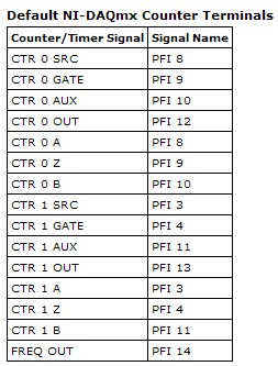
Big question. The screenshot below will give you the Signal of Counter/Timer associated with its respective PFI line:
This table is located in the NOR-DAQmx help (using terminals of NOR-DAQmx devices"OR USB - 6259 BNC).
To access these lines PFI one of the BNC (User 1 and User 2) user-defined, the line due to PFI line of the user desired. For example, if I wanted to access counter 0 Out of 1 BNC user, I would wire pin 1 USER on pin 12 of PFI. Manual specifications USB-6259 BNC does not give a good description of how to access the user 1 and user 2 BNC, so I refer to page 9 of the Manual of the BNC-2110. It's the same idea, just different pinout.
Let me know if you need more information. I hope that you are having an amazing day!
-
RF Mux PXI-2546 driver stops working when DAQ SMU-6259 is used.
Hi, I am experiencing a very strange thing. I have a system with two 1065 equipped chassis with about 15 different instruments.
It was working fine and has done for several years. Today the SMU-6363 DAQ crashed, I tried to replace it with a spare DAQ SMU-6259. I started with switching just the daq spare in but then the computer crashed every time during the installation of the pilot SMU-6259. So I thought that I need a driver update and installed DAQmx 15.1 (previous version was 14.5). It has not made any change. Computer always crashes constantly. Finally I found that if I remove the PXI - 2546 Rfmux in the SMU-6259 DAQ system will install and work properly. But now Rfmux PXI-2546 will not work when acquiring data SMU-6259 are installed on the system. I can get the Rfmux to work if I take the DAQ and vice versa.
Why is it like this and what can I do to solve?
I do not understand why a PXI-2546 Rfmux and an SMU-6259 DAQ interfere with one another.
/ Erik
Hi Anton, thanks for your answer!
Yes, it's very strange. I narrowed down it to these two devices. I got the blue screen during the installation of the Windows driver. So I tried first update the driver OR DAQmx. Who did not have any change.
Then I tried to roll back the NOR-DAQmx driver to a previous version. Crashes stopped then, but I could not both devices to work simultaneously. In the windows Device Manager, he showed a problem for the NI DAQ PXI-2546 peripheral device. I don't know why a mux is considered DAQ hardware either. The description of the problem says "some free resources". If I could get the Rf mux to work if I unplugged the daq and vice versa.
For the last two days, I was reinstall the system from scratch. I'm not done yet because it takes so much time to do this, but it seems to be ok now. But what a pain. I started with just the driver Rf Mux (Switch).
To do this I had to download almost 3 GB! For a 2 x 4 x 1 Mux driver. Then, the driver for the installed switch some NOR-DAQmx which I had to then update and download even more.
I think that NEITHER makes it very complicated with the pilot stuff. Instead of having these huge drivers packages which supposed to cover everything, it would be better with the smaller specific device drivers that could be easily found on the web under each device.
In any case I hope it should work ok now. I wonder what will happen when I get home my repaired SMU-6363. Should I plug it in or simply do not bother because I could face the same problem again?
/ Erik
-
6259 switch digital input to output
Hi all
I use the NI PXI-6259. One of the digital inputs I want to switch to digital output, send a serial code and switch again one digital input.
Does anyone have experience with this kind of configuration change during execution of the VI program.
Thank you
Basically delete the task that he had as an input, create another task DAQmx with channel configured as output, this task, erase it, create the task with channel configured as an input.
If you need a tight with switching schedule, I wouldn't recommend this Board. You may need to set up a Council of RIO with LabVIEW FPGA.
-
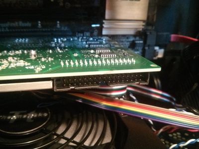
What is this on my PCI DAQ connector? (PCI 6259, M-Series)
I'm building a new rig which includes a PCI-6259, am confused by this connector:
What this is, and which mates with it? This is the place where I expect the power connector PCI-E to the power of the system, or the 'hard drive connector"that the M series is supposed to have. But this has about four times as many pins I guess than to have. It is not schematized or mentioned in any job I can find online.
Yes, version PCIe card has the supply and on the back of the card connector. The PCI version does not work. I think it's because PCIe is a lot of current as long as PCI, so the extra power is needed.
Both versions have if the RTSI connector.
-
My PCIe-6259 will work in a different PCI slot?
I have a DAQ PCIe-6259 case in an old computer that experienced a motherboard failure. I'm looking at building a new computer, but I wonder if I have to get a motherboard that has a dedicated x 1 PCIe slot, or if I can put my PCIe-6259 in a different PCI slot? I would also welcome the recommendations of the computer/motherboard.
Your knowledge would be greatly appreciated.
Thank you!
It must be a home PCI Express (PCI, not), but it doesn't have to be a PCIe x 1 location; Peripheral PCIe work in PCIe connectors longer, they don't just use the additional lanes.
-
The channel numbers and the USB-6259 BNC
The front panel USB-6259 BNC labels BNC connectors as channels 0-7 and 16-23. Most odd... I have a software written in C++ using NOR-DAQmx that my client will try to use with this unit. When using the channel superior numbers he (not unusually, really) Gets the error-200077 saying that they can only be used in unbalanced mode. But it is not natural for him to use the channel numbers printed on the front of the unit.
Can someone tell me how the front panel of this device is the channel numbers, you must specify in the code?
This requires the switch (source of the source/grounded) floating FS/GS that appears under each BNC connector?
Here's my proposal: differential mode: in the software, channels 0-7 are front channels 0-7. Software 8-15 channels are front 16-23.
Asymmetric mode: software channels 0-7 are cover 0-7 and 16-23 software channels front 16-23. And 8-15 and 24-31 channels are absent...
It takes just the opposote of what you have. In differential mode, aix is paired with aix + 8. so, ai31, ai9, AL10, ai11, ai12, ai13, ai14, ai15, ai24, ai25, ai26, 27, ai28, ai29.ai30 and ai8 channels are not available for selection in differential mode. Front panel for ai15-23 labels should be correct and matches what you select in the software.
-
Card PCI-6259 is compatible with the Dell Precision 390?
Hi all
I need help in answering this question. I want to buy a better computer for my data PCI-6259 acquisition card. I tried to search to see if the card is compatible with the PC and there's previous numbers with this set-up before other users. Do you have a link to the list of the DAQ cards with tested PC configurations? I want to just make sure that when I buy the computer, everything will work without problem because I only have one shot at this.
Thanks to all in advance.
Kind regards
justdomechanicalengineering
Hello
We do not have a link to specific DAQ board/PC pairings, but the specifications for the Dell Precision 360 indicate that she has three ports PCI 5V which must be compatible with your PCI-6259.
Best,
Dan Nelson
Technical sales engineer
-
Communication problem between LabView and acquisition of data USB 6259
I want to monitor a data USB-6259 acquisition using LabVIEW 8.6. However, when you try to create an explicit task (using the DAQ assistant) in order to acquire a signal, I get the message asked supported device found¨. I can see the USB-6259 under ¨Devices and interfaces¨ to the MAX, but when I try to import the configuration data for NOR-DAQmx 8.7.2 in MAX, I get the message ¨Can´t import file configData.nce. File not found¨. I use NEITHER-DAQmx 8.7.2. Any suggestions?
Corneliu
Hi, Corneliu,
This question could be generated due to a corruption of database of MAX. Here is a link to restore the database to the MAX.
http://digital.NI.com/public.nsf/allkb/2C7480E856987FFF862573AE005AB0D9?OpenDocument
Just follow the steps and let me know if that solves the problem.
A greeting.
Jesus.
-
I want to develop an application in real time on PCI-6259 with Matlab / Simulink, but I don ^ t know this device supports Simulink or not.
Hi umutozkan...
Thanks for the post and I hope that your well today.
First, you must be the MATLAB® Data Acquisition Toolbox, which can be used with NOR-DAQmx. OR Simulation Interface Toolkit (SIT), which, by default, generates DAQmx screws to connect with map DAQ. It seems to your post your using Matlab, so option 1.
The Data Acquisition Toolbox version 2.12 supports DAQ hardware that uses a software driver OR-DAQmx or NOR - traditional DAQ . MATLAB supports supported version 8.5 or higher OR-DAQmx and NOR-DAQ traditional version 7.3 using this box to tools.
The Data Acquisition Toolbox 2.8 version has been made especially to work with NOR-DAQmx 7.5 and 7.3 of NOR-traditional DAQ. Older versions of the Toolbox of Data Acquisition for MATLAB® versions of NOR-traditional DAQ support only.
Site Web IThe the Mathworks, Inc. has the latest support information about NOR-DAQmx.
See all this forum long post.
Use with DAQmx M series cards in Matlab!
http://forums.NI.com/NI/board/message?board.ID=250&message.ID=10165
I hope this helps.
-
Create two independent signals and a pulse train with NI USB-6259
Hi all
I'm new to the forum, I searched but I've found no info about it.
I have recently set up a vi that is able to generate from an NI USB-6259 case two different signals in frequency, amplitude and phase (see attachment).
To do this with each cycle of the memory buffer size is changed accordingly for frequencies in order to see a whole number of periods and, thus, having not leak in the generation (or breaks).
Now, I would like to generate a pulse train at a frequency that is an integer multiple of the frequency of the input signal (not the 50 Hz one).
The resulting frequency of the pulse train could be changed on the fly (or at least be updated at each new round of vi).
I'm stuck because I have already said that two analog output channels and I want the pulse train so that a digital camera for my Board (channel PFI) output, you have any ideas?
Thank you very much
Alberto
PS. the vi is "program generazione.vi" but you must first install "signal.vi production".
Hello
It is a simple .vi which generates a configurable, buffered pulse train dynamically. I also want to let you know that with this type of advice (DAQ), it is impossible to update the output in real time. You must be careful because the time between you use "DAQmx Write" and the output effective physical change not IS NOT FIXED.Kind regards
Matteo
Maybe you are looking for
-
New update will not download on my Macbook Pro 2012
New update will not download on my Macbook Pro 2012?
-
Connection PBS on 3rd Gen Apple TV
The PBS app will not leak any content, it doesn't have for a week at least, on two quads in my house. (Yes, I'm in the United States) The only message I get is "a connection with PBS is could not be established." Is switched off, back into the thing
-
open copy vs ios spreadsheet numbers App
I have set up several excellent spreadsheet to transfer in the iOS app via iTunes numbers. Numbers gives no option to "open" the files, if their file type is of numbers or Excel. But... I can "copy". Is 'copy' the newly darkened Word for 'open' in
-
Problem downloading program practical driving test success
Problems with the installation an error message and the program says d3drm.dll is missing on my computer. What this mean and how can I fix this please?
-
show / hide the Group of radio buttons
How to set the visibility of a group of option buttons? Basically here is what I have, I have a radiobutton group which shows, if a user selects a specific element in this radiobuttongroup, I want a second group of radiobutton to become visible as th