8051 C in multisim
Hi people
Could someone point me in the direction of all documentation on writing C for 8051 in Multisim?
It is more precisely C, asm not
And especially for the multisim 8051 compiler.
I'm new to multisim, if I have a lot of experiênca with the 8051 and C I can't understand how to reference pins MCU and records.
try to include the results of the reg51.h an error and of course without this code as "P1 = 0xA4" gives an error because the compiler does not understand "P1".
I tried the google search this site and the site of Hitech for these simple elements with no luck, all using asm or is a thread unresolved / unanswered...
Thank you very much
I haven't used the hi-tech compiler of in Multisim, but I use it as part of MPLAB to take pictures but I think it's the same thing.
The function must be declared as type of interruption and have not all parameters, for example: interrupt Sri (empty)
This function will be called when ANY interruption is detected. You need configure and activate the first interruptions. If you have several sources, they will all call this function.
Look in the folder C-Tech docs in the manual installation directory. Mine is C:\Program Files\HI - TECH Software\PICC\9.80\docs\manual.pdf. My manual has a section "INTERROMPRE HANDLING IN C".
Tags: NI Software
Similar Questions
-
The following program is unable to reach good results. I find the problem with oscilloscope as "the PIN TXD of 8051 cannot produce clock to exit", in fact, it should provide for outdoor clock, after "MOV SCON #10 H.
Is this a bug of multisim?
ORG 0000H
AJMP START
ORG 0100H
DEPARTURE: CLR P1.0
SCON MOV, #10 H
SETB P1.0
JNB RI $
MOV A, SBUF
MOV P2, HASSJMP START
ENDHi Yufei,
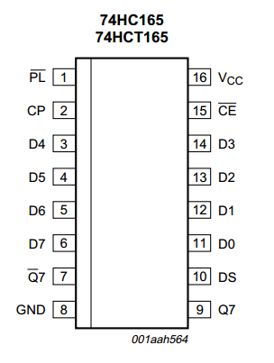
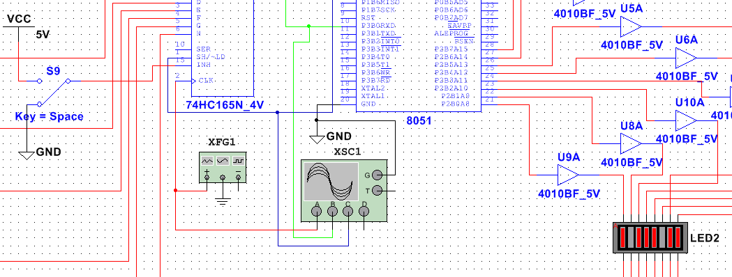
Thank you for your schema. I found the problems and got them fixed, the first is the way in which you use the 74HC165N.
According to the datasheet (connected to the last), CP is the clock (CLK) signal, PL (low enable) is to load the data(SH/~LD), THIS (low enable) is to allow the clock (INH). On your diagram, you have not activated the clock, that's why you don't have the output to the end QH.
To fix it, lower the level of logic to INH (15 pin) when you want to send signals.
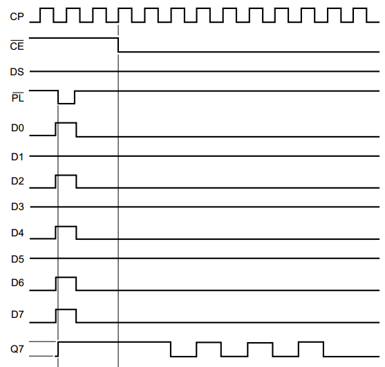
The second problem is the clock to TXD signal. Real serial communication, must exist. But here in Mulsitim, we already build it inside the simulation. It is no need to care about this now, just as there is no need to add an external oscillator between XTAL1 and XTAL2 of the MCU ends. But, here, we must add the clock using the function generator to the 74HC165N.
Run the simulation again, set 8-bit information and pull downwards of INH to send it. You can then see it displayed. :-)
Attached are the modified file and the data sheet 74HC165N.
Hope this helps! :-)
-
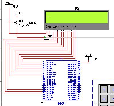
MCU: Metalink 8051 assembler and LCD_Display_16x2 problems
Hello
I'm currently building the 8051 tutorial here:
But I have problems in Multisim. I create the circuit and seem to connect everything correctly, at least multisim don't is complaint not and assembler doesn't mind my code, but he could not navigate to the build directory, so I loaded the file .hex instead, but he LCD does nothing. I have attached the files, can someone help please?
It seems your beginner to multisim.
U must Notea thing.
The display module Controlwords changes from a builder.
The codethat you have connected seems to be simply copied from the Web site.
To find the instruction bytes to the given LCD display click information in the Properties window for the LCD.
and some of the routines written for your tour are just useless
Find the file of work below. some changes are made.
Regaurds
A.Chaitanya
-
Multimeter simulation Multisim not showing after reading press simulation
I'm running student multisim version 14. I made a very simple circuit and to place two multimeter and run a scan dc.
But the problem I am experiencing that I'm window calculation but multimeters not show any value of simulation.
can someone help me understand this please.
Hi shabeesatsangi,
The meter components are intended to be used during the interactive simulation. When you run the DC OI analysis, you will see the results in a table in the grapher.
To display the values in your multimeters, change your simulation mode to Interactive and run the simulation.
I hope this helps,
Jeff
National Instruments
-
HP and/or Techtronix Multisim and GRAPHER
Is there anyway to have the results of the Tecktronix and the HP o-scopes in Multisim appear in the Grapher? Not sure why they don't, but they do not.
Hello
Impossible to Multisim to connect directly with third-party tools and import signals from the scopes in Multisim. If you are able to get information on the scope and create a file .csv with this information, you can import this file in Multisim.
I got this from another forum.
"The Piecewise linear (PWL) source accepts data as the voltage or current time. You can find this part by selecting site > component, go to the group 'Sources' then select 'Sources of voltage Signal '. Place this part on the working area, double-click it and there should be an option to open a .txt file.
-
Cannot install multisim 11 Visual c ++ runtime error
I always get runtime error while installing or multisim 11 on my PC my Configuration are Intel dual core 1.8ghz 1 GB ram and windows 7 Professional genuine fully updated what can be the possible reason, someone can tell me answer as soon as possible.
Hello
I've not heard of this error before (and we have installed on a number of Windows 7 machines).
Usually, when there is a runtime error, there is also an error code. Could you give me this error code. Also, when this error happen? You are uncompressing the installer, installer boot, while the 'parties' are being installed?
Finally, if you downloaded the installer, have you tried redownloading?
-
Import the SPICE model for transistor BJT BFP720F in Multisim
Hello
I'm trying to get the SPICE model for the BFP720F transistor provided by Infineon to work in Multisim.
I have attached the template as provided by the manufacturer.
If I import it as-is, I get error messages "invalid node identifier '<4>'" (I have translated that German, it might not be exactly this message in the English version).
So I tried to replace all the "<4>" with "4", which seems to help, but now the error is "adjusted temperature setting"VJC (PC)"negative" and "incorrect use of the parameters of the model. Now I don't really know what to do with it.
Is the template provided in the wrong format? I somehow can it in the right so I am able to use it?
Because I need for my project semester in College, any help would be much appreciated.
Thanks in advance!
Hi NikoNR,
When writing a detailed description of what I did exactly with the Wizard component, the component again to create in Multisim from scratch, I found that there are different SPICE models provided in the package for use with AWR MWO. They have a different file extension, but are normal text SPICE inside files.
It turns out that they actually work with Multisim. The difference is small, there is only one temperature (TNOM) setting that is absent in these models, distinct from the "general" I first tried to use. It seems that Multisim had a problem with this setting, leading to the error I encountered.
Anyway, the problem is solved now. Thanks for your help

Good day
(The now much happier) EE-student
----
Edit: I have attached the SPICE model, that I ended up using, in case someone at - he never met a similar problem. The only change I did this, is to replace '<4>' with '4' in the part of the diode (single occurrence here). I had to zip to download with his original extention (.mdl).
-
Multisim for transfer Ultiboard Glitch
Hello
We have made many PCBS using Multisim as our software for schematic capture and Ultiboard for layout. The last room back does not work because the netlist in the schema is incompatible with the netlist in the provision of one piece (which is used several times on the map). Not only all the pins are reversed, but one of the pins is quite non-connected. Since the 8 pins are connected to the schematic side, this clearly isn't simply a matter of mixed up of PIN, but when I annotate with impatience, it is said that found no difference.
I went through and double and triple checked the symbol, the footprint and mapping of the PIN, and everything is OK. As a witness, I created a new schema with nothing else that the part in question and transferred to Ultiboard, and everything was OK.
Everyone knows about this problem before? This is a known bug and is there any workaround or recommended solution to avoid something like this happening in the future (outside routing by hand and without taking into account the ratsnest altogether).
Thanks in advance for the help!
CDM,
Please contact our support group. You should not see this question in v11.0. I'm not aware of the important issues with annotation front/rear, since we redesigned the annotation capability and improved reliability in v11.0 (from 10.1).
http://sine.NI.com/apps/UTF8/NICC.call_me -> select ask support
Kind regards
Pat Noonan
-
I use LM1181 to scan my data. I build the tour that seems very well according to the data sheet of the Active Directory Connector, but I get the result as 000. and the PIN BACK a 0V instead of 1.5V. is there a problem with my circuit? I have attached my tour here. Help, please.
Is possible to export my data didgitized in text file?
Hello
In Multisim, there are two virtual ADCs, you could try: ADC and ADC16. They can be found in the Mixed Group, ADC_DAC family. They are not the real components, but they can be used in the simulation.
I hope this helps.
Kind regards
-
Hi all
I played a bit with multisim for a few years now, but later began to really use the features of simulation of the program. I noticed that transient analysis of the very basic circuits seem to work fine, but nothing more than (especially those using pwm controls) after bogged down as some ridiculously short period of time. Also, before it freezes, things as the output of the oscilloscope function very slowly. I have attached my circuit for reference and using all that you wonderful people out there. What I am doing wrong?
The wizard of error correction is not really take care of the problem.
FYI, this is a converter circuit high power for which I would like to study the out performance characteristics by changing the frequency of the triangular wave or setting of the amplitude of the sine wave from 0 to 1. The goal is to produce a sinusoidal current output to the primary of the transformer. The resistance of inductance and conductor of leakage have been modelled, as well as an inductive load on the secondary of the transformer.
Thank you!
Yes, I tried for a few days and all the other typical timestep of bugs and it does not always work. The solution was to replace the igbt with the command switches in idealized voltage and barrier diodes schottky antiparallel... and on the ground of the transformer floating seconday. It works now
-
Component USB 6008 in Multisim
Hello
I conceive my system in Multisim 12 and I wanted to include OR components of the database.
I need a component for the NI USB-6008 case and the other for the NOR cDAQ-9174 with two NI9217.
My question is: these elements already exist (in the database, on the Web site of OR or a third party) or what I have to design?
Thank you
csiquet,
Here is an example of a database of these parts NOR (symbol only):
To merge into your DB, to do this: tools-> database-> merge database
There are 'rated' components blow up / stop working if too much voltage/current passes through them.
Master DB-> base-> Rated_Virtual
Kind regards
Pat
-
I can make the subcircuit in multisim as sub - VI in labview?
in my project I have to work in modules, I can connect?
as we use slot - VI in labview, I do subcircuit in multisim?
Yes! "You can select just to the right of all the components that you want to do a subcircuit of and right click ' replace with subcircuit...
You now have a sub-channel that is registered with your design. "" If you like to have different files for your modules (I personally), you can create instead of the Sub-channel in a separate file, connect HB/SC connectors PIN you want to send signals to, save the file and in your main circuit, right click "Place on schema" hierarchical block of file... in this way, the module can be reused as many times as you want.
See you soon,.
-
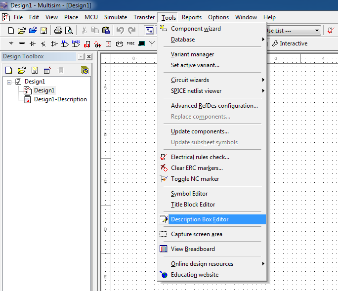
Document of several pages of text of Multisim
I use Multisim 14.0 and is working on a scheme that someone else did. One of the pages is a text document. How it was created? I would like to add a page similar to one of my patterns, but cannot figure out how. Thanks a lot for your help
Michael
Hi Michael,
You can place a description box (tex document) by selecting 'Editor Description' in the Tools menu:
See you soon,.
Jeff
-
student in multisim edition installation problem
I first installed the version of multisim student and uninstalled it.now I am unable to re install the program.i tried to solve the problem by removing the directory program files.please help me solve the problem
Hello
This error occurs generally if there is a problem in the installation program, or there are already traces of the software on the computer. If you could answer the following questions I'll try my best to help out you.
-Is the first time that you install the software? You have a previous version?
-Do you have other National Instruments software on your computer?
-What operating system do you use?
-You have an administrator account on your computer?
-Make any other mistake?
-
Multisim co-simulation / LabVIEW
Is it possible to add contacts from two States to Multisim and control of Boolean way to LabVIEW?
the attached example schema
Maybe you are looking for
-
I had a 3rd gen iPad and he fell, bursting from the screen. I bought an iPad 2 Air and implemented the backup of my old iPad. The new buffer using iOS 9.2.1 the old cushion used 7.1.2 but that shouldn't be a problem, right? So I implemented the new p
-
Where can I find for sense of database SQL IPCC of each table? I have the database db_cra and I would like to know the meaning of each table.
-
Cannot open my photo album of t-mobile of their site.
I have a new e-maching with operating system windows 7. I have no problem logging into my t-mobile account and access to my information. But when I try to open my photo album (photos I took with my cell phone and sent over the internet to my t-mobi
-
UCS Manager and using Microsoft Certificate Authority
Everyone crossed by the configuration process UCS Manager with a certificate issued by a Microsoft certification authority? If yes I would appreciate some help. I was able to create a request and have generated the certificate successfully, but I s
-
How can I accept an invitation from the team when my email client blocks the link "accept"?
Hi, I work in a company that uses Lotus Notes as an e-mail client. I was sent a team invite you to join their team CC, but the email I received Adobe has no link "accept the invitation." I know there is a there that when I send the email to another a