Background basket 1409 PXI trigger
Hello
I have an installed 1033-1409 PXI, PXI-5105 pxi chassis. I want to route a signal to trigger for PXI-1409 to the RTSI bus backplane and then use this signal to trigger RTSI bus trigger PXI 5105 as a trigger to start. PFI 5105 PXI is already occupied by the synchronization code signal Therefore, the only way to configure the startup to 5105 trigger signal. I'm using C++. However, after reading the reference of function and the examples coming with 1409, he does not seem such a function to perform this task of routing. Is it possible to 1409 and 1033 for this? If possible, could someone give me a short example? Any suggestion is appreciated.
Sincerely,
Bin
Hi Binar,
You will be able to drive a trigger on the lines of the RTSI with your PXI-1409. If you look at this knowledge base article, you will see that the projector 1409 is one of 5 Councils who have RTSI triggering capabilities. That being said, if you look in the NIIMAQFunctionReference document, you will be able to find information about the necessary trigger under NOR-IMAQ functions functions > functions high-level > functions of i/o signals. In particular, you will need to look at the imgSessionTriggerDrive2 and imgSessionTriggerRoute2 functions.
Paul M
Tags: NI Hardware
Similar Questions
-
Salvation;
I have an SMU-1065 with the following modules: PXI-6529, PXI-6280, PXI-5114, & PXI-6713. I have 3 questions:
1. how the RTSI is launched?
2. how this trigger can be monitored?
3. How can I create a task is triggered RTSI?
I'm fairly new to LabVIEW but I work with other more experienced programmers.
Thanks for any help.
4BoysDad
Hello 4BoysDad,
Before talking about your questions, I will provide some information about the cards you because I think it will help me to answer the questions completely. First, the PXI-6529, the PXI-6280, PXI-6713 uses the DAQmx driver but the PXI-5114 is a digitizer and uses the driver NOR-Scope. Knowing this, I would focus on the passage of relaxing between 3 maps DAQmx first before thinking about the PXI-5114.
At the same time, you have an SMU-1065 chassis. With this chassis, there are 3 segments of trigger bus essentially dividing backplane. If one of these cards is in a different segment, you'll have to correct bus together segments to spend relaxation through the bottom of basket. To see how backplane it broken up, please look at the Datasheet for the SMU-1065. I would recommend that you put them on a PXI trigger bus segment.
With that in mind, here are my answers to the questions:
1.) how is initiated the RTSI trigger? How to create a task is triggered RTSI?
Before doing so, you will need to select a master device to the other slave devices. If the master device is a DAQmx device and you are passing to an another DAQmx slaves, here's a example of how to implement this. The relaxation will be initiated by the master device and in this example, the trigger is a beginning arm (for more information about this, please see the DAQmx help). Looking at this example, the RTSI trigger is managed in the synchronization of tasks - Trig Skew correction. With outbreak RTSI, this VI also allows you to synchronize the clocks of reference for each of the devices. Given that this example provides detailed notes as well as step-by-step instructions how it works, I will not repeat the information here.
If you want to synchronize the card extended with DAQmx device or multiple devices, you will need to export the signal to the other card. This example explains how to implement the scope as a master and the DAQmx device as slave. As others explain, it provides a general explanation how to achieve this as well as step by step instructions how to implement this.
2.) how this trigger will do?
Regarding surveillance of relaxation, I looked in the DAQmx and the pilot of scope but also consulted with my colleagues, and it is not a function, we found who will tell you that the shutter has been sent. We found one way to check this is to use the timeout for task/sessions to see if they started. If they have not the trigger has not yet been sent to the other device. You are looking for this feature for debugging purposes or will you for use in your program somehow?
If you have other questions about this, feel free to post.
-
5154 PXI trigger on the external input
I use a PXI-5154 and want to change my previous program to trigger the external source. I'm feeding the external source from source to V 2.5 and it seems to trigger fine. However when data acquisition the vertical range of the oscilloscope will 5 V which is too high as to my request I acquire in the millivolts range. I tried to show the vertical range of the channel I acquisition, but although I put it as the active channel I get the following error:
Error 1074118616 has occurred to the property node (arg 1) in PD_measurements_v11_test.vi
Get a base attribute value channel failed because the channels interviewed have different values. Please specify a channel when you query a string based attribute.
I enclose you a printsceen of the relevant part of the code.
Kind regards
Karavellas
Dear Tunde
I managed to make the changes you suggested and the works of the example. I'll look in my code and see what the problem is. I'll get back to you if it has been fixed in my code or not.
-
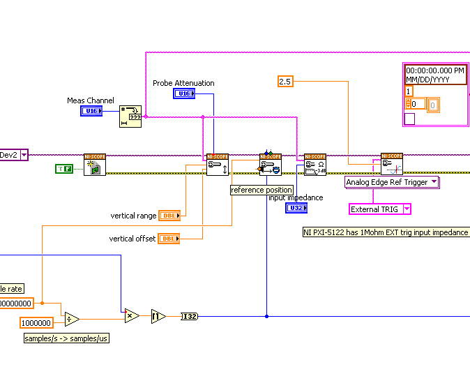
Hello
I use a PXI-5122 to record an external event triggered. When I run my setup using an oscilloscope, the relaxation and the answer are aligned (see first attachment, response is the most noisy, curved channel 1). Transfer when the installer for LabVIEW, the shutter is badly programmed and seems to happen until the trigger is actually received (see second attachment). The outbreak of the second curve point should be at the beginning of the climb and it should also be at t = 0. The trigger that I use is triggering external edge Ref-OR-SCOPE (VI included as the third attached).
I guess this problem is caused by the trigger being a trigger for reference, but I don't see other kinds of relaxation to use and I don't know how to deal with this problem. Can anyone help?
Hi Glen,
Looks like you're right that the problem is that the scope is configured to use a reference trigger. By default, the reference position is 50%, which means that half of the samples in an extraction will be before the outbreak and half occur after. The scope accomplishes this by storing data continuously as it is acquired in a circular buffer so that the most recent samples are available when the reference trigger is received.
In this perspective, the challenge is really very simple – you can specify the reference Position as input to the niScope configure VI of horizontal sync:
Fair value the reference position 0 (default is 50) and you will receive all of your data after the trigger occurs. A value of 100 would give you an entire record of samples before firing.
Best regards
John
-
Dear community,
I am trying to implement a background basket (software) PXI trigger on a chassis NI SMU-1082 with LabView 2015 (32-bit) running on an SMU-8135:
HS-DIO (SMU-6544) in slot 2,
-Acquisition of data (SMU-6363) into the Groove 4,
-Flex RIO (SMU-7962R + OR-6583) in the Groove 3.
The trigger schema is explained in the attached file ' LV-PXItrig-HSDIO-DAQ - overview.jpg ".
Scenario 1: written DAQ analog signal and sends signals trigger HS-DIO (software) through bottom of basket, after East of waveform of the complete signals to DAQ for acquisition.
Scenario 2: logical impulse on an external port HS-DIO triggers signals HS-DIO, after HS-DIO waveform is complete DAQ triggered for the acquisition of the ADC by the backplane.
In principle this breaks down to send a trigger of module A to B by PXI backplane. The SMU-1082 chassis has a bus trip with 8 lines (PXI_trigX, X = 0,..., 7) more a trigger in Star controlled the slot 2.
I've linked to implement a software trigger, but I can't access the refreshing resource and execution, see the attachment. Other ways of implementation including the DAQmx Terminal / routine disconnect Terminal have not worked for me either. I am aware about the connection of trigger using the node property VISA but I can't make a trigger.
Tips, comments or solutions are appreciated. Thank you!
For scenario 1, you want to trigger the HSDIO acquisition to begin as soon as the analog output DAQ starts? You can use
DAQmx Export Signalto send the trigger for the start of one of the lines from the Trig PXI backplane. Then, you need to configure your HSDIO acquisition to use a trigger digital beginning on the same line of trigger. Take a look at the example of the "Dynamic hardware generation start trigger" in the Finder of the example (help > find examples)For scenario 2, looks like you do a dynamic unit HSDIO generation when a digital trigger arrives on one of the PFI lines. Once the build is complete, you want to send a trigger for the DAQ hardware to begin sampling. If this is the case, you again use a trigger to start material in your task of NOR-HSDIO, as you did for scenario 1, but use external trig line as the source, rather than the bottom of basket. There is no case of material when the build is finished, but you can use a marker in script mode event instead. The example of the Generation with dynamic event marker' in the example Finder gives a good starting point for this type of operation. You'll want to set the output terminal for the event to be a line of backplane trig, and then tap the DAQmx to start on the same line trig trigger.
-
Hello colleagues LV coders.
I've looked everywhere and can't find the answer to the following question: How can I access a trigger in Star in a PXI 1031 DC chassis? I know this must be through SLOT2.
I currently have a micro controller PXI - 8102 SLOT1, an arbitrary generator (AWG) pxi-5422 the SLOT2 and a PXI-7954r FPGA with a digitizer 5761 nor in SLOT4. I know that activitate the outbreak in Star, a "Timing and synchronization' card must be in the SLOT2. Is it possible that I can use either the microntroller in SLOT1 or the Working Group in the SLOT2 for access to the relaxation of Star? I think that the microcontroller will probably be able to reach, but what about the Working Group?
Follow-up on issues is as follows: suppose that I am able to implement this Star trigger correctly, once the working group receives the signal to send its chirp 10usec by having the Star trigger go HIGH, is there a way of simultaneously to adjust the line of PFI0 HIGH in the Working Group and a time that the 10usec is completely sent to set the PFI0 on the BASS line in the generator of signals for usec then 90? This could be repeated indefinitely and the PFI0 line is used to control a switch via a cable. In addition, this PFI0 of the GTS line will always be equal to "output mode".
Thanks in advance a ton. If I found the answer elsewhere, I'll make sure to update here.
-Daniel
The link "what GIS speeds. do my chassis PXI Trigger lines Support' really helped me to understand how triggers are connected in the bottom of the basket of the PXI chassis. In my case, I need my shutter button to get to the e in 1 usec and thus the PXI Trig. Bus to get there. No need to worry about the outbreak in Star for my application. Thanks for the research!
http://digital.NI.com/public.nsf/allkb/892204272FF2C0BE862575C500636AF6?OpenDocument
-Daniel
-
Trigger the playback status of the PXI/lines of buses in a PXI system
Hi all
I ' am, developing an application in which you cards inserted in the PXI chassis will send a trigger on the PXI trigger line signal 0 1 bus, while another card on a different slot waiting for the trigger on the trigger line specified. These two cards are cards of third parties (OR not) who support the trigger through its drivers and are inserted into the slots which is part of the trigger bus Beach chosen. (My frame has 3 bus trigger). It seems that my second card does not relax. So I don't know if my first card actually generates a trigger on the specified line. So I would like to know if there is a technique to control the States of triggering in labview, so that I can check if the trigger is actually that occur or not.
Note: because the cards are third parties, I booked the line trigger PXI 0 in NI MAX settings for my chassis.
Waiting for a quick response.

Oscilloscope? Connect an entry is not used for the trigger signal?
Mike...
-
Impossible to send software trigger using 6682 and OR sync
I can't send a trigger of global software to the PXI (PXI_Trig0) trigger using the PXI-6682 card and the software of synchronization OR (beta 3.0 and 3.1). I ran the example vi: route software Trigger.vi and chosen my 6682 and terminal of destination PXI_Trig0 resources. I get the error:-1074118606 was held at niSync Connect Software Trigger.vi, driver status: (Hex 0xBFFA4032) the terminal specified source is not valid for this operation. Looking at the terminal of the source, it is selected as the GlobalSoftwareTrigger. If this card does not support a software trigger (I can't imagine why), if not, how can I send a software inside of basket PXI trigger trigger?
Any help would be great.
Josh
I found this one. Apparently the PXI-6682 card cannot do a software trigger, so I plugged internally PFI2 to PXI_Trig0, then an event of installation time (down, up, down) on PFI2. Time event fires a trigger on PFI2 that triggers a trigger on the backplane PXI PXI_Trig0. I will then put up to fire all stars fires instead of PXI_Trig0 to synchronize my two FPGAS.
-
How to use pine TRG in controller PXI-8176
Dear all,
I have the Thermocouple data acquisition system. In which there are 2 PXI chassis (1) 1002 with
PXI8176 controller with RT, map 6071E PXI data acquisition (2) block 1001 SCXI with SCXI-1125 and SCXI1327 card.
PXI 6071E connected in 1125 SCXI with SH1006868 cable and adapter SCXI1349.
I'm using Labview 8.6, DAQmx9.0
I develop the program for the continuous acquisition of thermocouple. Now, I want to do the program on the acquisition of database trigger. When the trigger pulse comes the system begins to acquire (newspapers and data in the file) to userdefine times and stop the acquisition. Again when the trigger pulse comes new system begins to acquire and to stop at defined time.
There is a single pin FIT on the PXI-8176 controller, can I use that one and how do I use it? Or I have to use the separate DIO line for trigger?
You can guide me how I can develop this system.
Thank you.
-Vishnu
Yes, you can route a trigger for channels PXI trigger in the bottom of the basket of the PXI chassis via the SMB connector located on the front of the PXI embedded controller.
Please see tutorial following example or the same article on devzone
Hope this helps
-
OR TB-2605 terminal block for the NI PXI-2503 relay card PIN GND interconnection?
I use the relay Board NI PXI-2503 and the NI TB-2605 terminal block to impliment some of interconnections, my question is on the Terminal it is a GROUND terminal on the GND PIN. What electric pins or card background basket or internal relay Terminal this 'point' interconnection to?
Hello gene01,
I don't directly know what this PIN connects to. Following the trace, that looks like it is connected to the mass of the chassis as the 2503 itself does not have a grounding pin. I have this will confirm for you, but is there a specific reason for your application need you to do this?
-
Help with PXI OR 4070 DMM and OR PXI MUX 2501
Dear alls,
Sorry to post a simple question, but I couldn't understand it.
My PXI1033 chassis has NI 4070 Flexdmm and NI PXI MUX 2501, block of connection OR-TB2605, 1 thread by MAX-mode configuration.
I'm trying to measure 3 voltages (from 2V to 5V) by connecting them to ch0, ch1, ch2 MUX2501 (Terminal screw for example 67,66,65 and common screw terminal 27).
Any device passes self-test to the MAX.
I then use NOR-DMM/Switch Express, swap the added devices and also scan list.
Trigger is PXI; Handshake (PXI trigger 0 and 1 PXI trigger)
However, I could not measure all the signals.
I also try with other examples in LabVIEW help, but have still no results.
Am I missing something?
And, although the trigger section is very clearly explained, I have no idea how the DMM to run his measure through switching and multiplexing. How DMM connected MUX?
I noticed that the DMM and the switch share the same trigger bus (two of them bus trigger 1), but their local buses are different (DMM: local bus left/right = 2, 4, and buses premises MUX left/right = 3.5)
Your advice is much appreciated.
Thank you.
Van.
Lonestar thanks!
-
What is the PIN Vsup and how to connect to the bottom of basket NI 9932?
I use the NI 9474 with background basket NI 9932 connector with that he came. I have skills EA of a rock, so I apologize for these basic questions:
What is the PIN Vsup, and that means the "sup?"
I'm trying to connect the LED to the NI 9474 (I know there are some on the module already;) I would like to try some store bought). Does anyone know how can I go about it?
Thanks in advance.
The 9474 requires an external 5-30 volts continuous. It's what connects to Vsup. The "sup" stands for "supply".
-
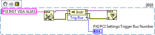
Identify the PXI properties to decide if you want to route triggers on PXI bus segments
I have an SMU-1075 and a SMU-1062 q chassis. Each has a similar map configuration.
Initially, I developed my request for the chassis PXIe1062Q, routing a trigger by the generators of card synchronization signals and a digitizer. When I run it on the chassis of 1075, I send 2 to the segment of bus 1 bus segment triggers so that triggers the calendar cards reach the scanners and the signal generators. On the chassis of 1062 q, this is not necessary since everything is on the same segment.
I used the article routing programmatically Trigger lines through a Multi Segment PXI, PXI chassis to properly route my trigger.
Is there a way to determine how many bus segments I, or Wow, I use to do I connect automatically triggers (or not), so that I can use the same VI to control two hardware configurations? I don't know what happens if you try to connect through triggers of bus segments that doesn't exist may not, but I wanted to know what is the correct way to deal with this situation.
You could pull the trigger bus number using NI-VISA. Just give your devices one alias VISA to the MAX and you can use a node of VISA property to get the number of PXI trigger bus. This should help you.
Best,
-
Hello together
My question is how to put a PNG on a trigger
The problem is, when I do the background transparent relaxation, it looks that it works. But if I try to roll out of relaxation there is the background across the visible trigger and not only the PNG
Can someone help me?
You must follow these steps:
-Place the slide show
-Add the image you want to use as a background for trigger
-Go to the active panel
-Select the new image to repeat and trigger.
Thank you
Sanjit
-
With the help of the external RF signal generator
Hello.
I just want to ask how can I remove the frequency shift if I use an external RF signal generator (instead of the RF PXI-5652 signal generator module). I understand that in the case using the OR to generate RF signals, frequency shift is deleted by setting the same source of reference for the transmitter and the receiver clock (placing the clock source of reference to PXI_CLK of the façade of generation VI and VI of the acquisition).
Thank you very much.
Hi Betty,.
In this case, no changes are needed, such as modules OR still use background clock basket PXI as the ref. clock source If you are still having a frequency shift, you probably need to configure sig gen to lock a clock external REF. Usually, just make the connection of the signal is not enough - you must also indicate the sig gen to use the signal connected to the input clock ref. Terminal
If you use the sig gen as clock source master Réf, connecting the 10 MHz of the gen of GIS at the BNC 10 MHz IN on the back of the PXI chassis replaces the clock native from the newly connected with the PXI chassis backplane, and analyzers are still using the clock background basket PXI as the source clock Ref (no change to the SW settings).
Kind regards
Andy Hinde
RF systems engineer
National Instruments
Maybe you are looking for
-
Of 'date and time' I tried to drag the month and year of my menu bar. He did not stay, I did several times, but nothing helped. I closed the window and went back to my Thunderbird email to see the date, I tried to use became the date in the column "d
-
Specification of MIC on the NB100
Hello!Everyone knows the electric characteristics of the microphone on the NB-100?Could it also be used as a line input (perhaps by adding some mitigation)? Thank you!
-
Hello I am currently using SMU-7966R with module of e/s-6583. For my application, I need to access IO with imported vhdl design FPGAS. As a result, I try to use a CLIP half bridge. Following the tutorial process NOR, I imported a CLIP half-bridge (fo
-
Exchange 2003 Migration to Office365 with SSO
Hi all Merry Christmas to start! I work for a company that run Exchange 2003. We plan to do a migration to Office365 and I am researching on the best solution. I am aware that there are three main options available, hybrid/intermediary/putting in ser
-
Unexpected i/o error has occurred. Status: 0xc00000e9 setting from the Setup program
Please, I have a Toshiba labtop, what sudenly accident and it does not open windows, this message appears at the beginning upward: unexpected i/o error has occurred. Status: 0xc00000e9