Beginner LabVIEW
Hello
Unfortunately, I am Labviewanfanger, I ask your help and we hope that you will help me.
I need to create a table using the loop, the elements of the array must be monotone increasing so by 1, it must match the size of array, the number of loop current loop. I hope I have described my problem properly.
If an example.
--2 3 - 1 0 1 2 3 4 5
--9 10 - 7-8-6-5 - 3-4-2-1
0 1 2 3 4 5 6
5 6 7 8 9 10 11 12
Tags: NI Software
Similar Questions
-
Beginner LabVIEW - XY graph and audio files
Hello
I am very new to LabVIEW. I'm doing a program as follows:
- The LabVIEW VI to simulate two temperatures of entry.
- You can simulate each of them through a random number generator (be sure to keep the numbers in a temperature range of imaginary), or if you want to, by reading the values of a file.
- The Panel should, at a minimum, instantly showing each temperature (e.g., using a digital display), a graph drawing each temperature with time and an indicator (for example an LED or the counter number) to show that the temperature has exceeded its threshold.
Now I have the generator of random numbers and Boolean lights according to work properly. However, I recently added sound if the temperature drops too low (i.e. when the blue led shows) or too high (when the red lights). It works well, however, for some values sound custom ring, for others it will be. For example, three values in a line could show who are all under 16 years - the lower limit, the blue goes light on however the noise could only ring - its my default windows sound. Can anyone see anything wrong with it or offer me a solution?
Then, the XY graph. I feel that I don't get the right settings in there. I want the number of seconds on axis through the temperature values on the x - y axis. The temperature values initially came out huge by default, I have not changed the name of the axis but theres no graphics if I resized the axis myself? In my view, that I've not connected properly maybe? Also I really think I have somewhere went wrong with my reading of axis x, maybe I have the wrong time function in the control panel? I amn't familiar with boolean or or how to define true/false?
If I wanted to use 1 LED that could change in three different colours (red for high green, temperature temperature normal and blue for low temperatures), how can I do this?
Finally, someone has suggestions for the user interface, to make it look a little more sophisticated?
Thank you in advance, attached file.
First of all, you want to work on both your temperature at the same time and display them in separate indicators. Secondly, I am sure that your beeper goes with each temperature taken. You want to put the tone within a business structure to make it sound when you have any out-of-range condition.
So in the end, I'm sure you want a Setup like this. I'll leave some work for you to do. You are not nearly enough to pay me to do your work for you.

- The LabVIEW VI to simulate two temperatures of entry.
-
Hello
I want to write data to a text file. Don't ask me why, I have to use the vi 'Write in the text file' and not 'write in a measurement file. Everyone do in my office.
The point is that when I use the vi, the file is always overwritten, if I want to add data in the same file. See attachment for a view of my program. Obviouly, I'm trying to find an option in the property, but no... I sent the vi outside the lopp, but it does not work
Oddly, it works very well with Labview 2009 but not Labview 2010
Someone has an idea?
Thank you for all
See exhibit attached - open the file, move it to the end, write the text, close the file.
You can also write at the beginning of the file, or to jobs in the middle.
Ian
-
What to do to keep a Boolean pulse?
I want to generate a Boolean pulse and then hold this value until a new impetus, as a CRS to electronics.
I am a very beginner labview user, so I ask you guys to be as clear as possible. If you could send me a VI he would be great.
Thanks to you all!
Well... There are a number of ways, depending on what you are trying to accomplish.
If you use a while then you might add a registry to offset at the border of the loop, initialize it to 0, set it in a part of the loop, and reset it in part after it is read in a loop.
You could also put this function in a functional global variable (FGV) sub - vi. There are many examples and tutorials on the Web site of NOR. This could potentially give you more features at the expense of more complex code.
If you use the tip like a flag in a different part of the program then semaphore or notifier can be a good solution.
See you soon
-
Enter the external value in the while loop
Hello, I have the following problem. I am beginner labviewe and I created a simple program to record data and control a laser printer driver. The problem is:
at the beginning, I'm in the temperature values and current - they must be outside of the loop, because I want to include these start values in the header file that I add the file initially.
Then I go into the loop, but if the control is on the outside I can't change the value more.
So here's the question: what to do to be always able to change these settings without creating more control?
Sorry for the mess in VI, but I'm just getting started.
Thank you very much
Maciek
Hello
A quick solution, create a local variable for the control to use in the loop. Best solution, plan to implement a state machine design model so put everything before the loop in the first State, before moving on to the main report (the stuff currently in your loop). In this way, you would be able to access the control of these two cases which is preferable.
Hope that helps,
-
Photo balloon with mouse over.
Hello
I'm sure this has been answered before, but after a long search, I have exactly what I'm looking for, so that's.
I want to have an image pop up when a user "hovers mouse over" a command or the indicator on a façade for a time.
I am a beginner @ labview so be very descriptive if you can.
Signed NOOOOOB!
It must be backsaved. He loses the functionality in the translation because things did not exist in LabVIEW 7.1. However, by looking at the code, the mode of operation is that it displays makes a web browser on an indicator of the photo control. The intention is that it can display animated GIFs. If all you want to do is viewing a static image, then you can do something like the example attached.
FYI: To save the screws in earlier versions of LabVIEW, you can post a request in the thread Downconvert VI requests .
-
Accounting of the derivative of the signal
Hello
I am a beginner LabVIEW-user and I have a question that maybe painfully obvious for a more experienced user.
I use a precision Sartorius CP225D balance to save the change of mass scale mg due to withdrawal and the dispensation of a fluid in a container. What is the piece of blocking air flow, bringing the temperature of the room and immutable or reposition the initial load for several hours, a fairly linear and continuous negative drift will occur for the display of the balance. This drift occurs without worrying if there is anything on the scale or not. I use VI Sartorius provided to read and note the readings.
How can I use LabVIEW to adjust this signal for this negative drift using the linear relationship I can derive from the previous examples of execution? I tried to collect the signal of the difference between the display of the balance and the linear relationship that I approached, but with time, even this manipulated signal falls to the display of the exact balance if he were allowed to run without being manipulated. Better yet, how can I manipulate the signal of a frame sequence curve flat prior connection for the signal already recorded in the following picture?
I would appreciate any guidance or assistance that could lead me to a solution. I tried to contact helpline Sartorius, but little help was offered. I will share as much information as possible.
Thank you for reading this,
Zach
Zach,
The instrument drift probably not linearly forever or the value wouldn't finally out of reach. The manual I have donwloaded requires 30 miniute, 4 hours or 24 hours of warm-up, depending on the model and the application.
You can try saving records once per minute for 24 hours, starting by an intstrument of cold and let it run as stable an environment that you have available? Note the temperature, if possible. Never stabilizes the drift?
What is drifting from the signal you need to measure? What is drifting? How fast your fluid distribution affect the readings?
Lynn
-
Mark an object in real time on a displayed video acquired of a USB camera
Hello
I'm a beginner LabView user company acquired a project in which I need to see the video from a USB camera in LabView on computer screen. In the video, there will be a piece of metal, which is always a fixed position at the bottom left of the view. I need to mark a sign like arrow on the metal part, please take a look at the attached picture. In order to recognize the easier metal part in the photo, I drew a line of blue on the edge of the part, while the arrow was green. The arrow must point radially towards the center of the blue line (but the blue line may not need to be created) and must be there whenever I start the VI, throughout the video.
How to view the video? Is it possible to create the arrow in LabView (either programmatically or manually mapping arrow)? If it is impossible to make the arrow, is it possible to simply mark a cross in the center of the blue line? The blue line doesn't have to be on the video.
I have 2010 LabView with Vision Development Module. My camera are in the outlying NI-IMAQdx able and Automation Explorer section.
Thank you
LePhuong
Hello
Look at this post. It can help you. http://forums.ni.com/t5/Machine-Vision/pattern-matching-program/m-p/1914589#M34855. Here the video signal you can replace this with live video.
-
Hello
I am a beginner Labview and am looking for the solution pour dialogue with equipment (transmitter SCAIME measuring weight) in Modbus Protocol with a not variable between 2 interrogations and record responses in a file.
Frame problemas en of I know the Hexa format pour mark and the response of the transmitter, en revancheje don't know what VI nimodbus UTI.
Thank you in advance for your help.
A +.
Please try to post in English here
Translation
I'm from Labview and I'm looking for the solution to interact with the material (transmitter measurement weight SCAIME) in Modbus Protocol with a not variable between 2 questions and record the answers in a file.
I know that the image format to hexadecimal for the request and the response of the transmitter in revancheje don't know don't no how to use nimodbus VI.
-
Beginner's Guide to out of Labview to MySQL data
Hello
I am a student who has started only recently, using Labview for a data recording project, so that my knowledge of its use is rather absent. My current goal is to be able to get out the data stored directly in a MySQL server, so that data are accessible remotely via internet and processed using PHP scripts.
I have some basic knowledge of MySQL, as I've previously used to create dynamic web pages, but my knowledge of how it works is also a bit lacking. The MySQL database I want to connect to the stands remotely on a server of the University I want to connect to.
I saw that this connection is possible from previous posts, but I would really appreciate a basic account plus the steps I should follow to make such a link.
Thank you
Rob
-
Beginner question absolute to the Labview with GPIB connection device
Hi all
Firstly, sorry if my question is already posted, but I tried searching with nothing doesn't.
My situation: I have a HP digital osciloscope, a HP 54602 B using the GPIB and trial version of labview 8.6. Now, I want to communicate with her from labview. The big question is: how? Before that I used only labview with NI DAQ card and serial port for communications of the instrument.
the detailed question
1 is it important (to programming in labview later) what GPIB interface that I use in my computer? Must be of OR? I still have no interface right now.
2. I ran a search on the osciloscope Web site of NOR and find an instrument driver in:
. How do they come?
3. I know there are a few examples for the GPIB, but since I do not have the interface, I can't try it. Is it possible to simulate instruments GPIB?
Thanks for all your help and assistance
Hi opiq;
Welcome to the world of instrument in LabVIEW Control! I'll try and answer your questions one-at-a-time:
- N ° from a point of view of LabVIEW, you can use any interface supported by VISA and your instrument bus. This includes (but is not limited to) boards of NOR-GPIB, 3rd-party GPIB, USB, LAN, LXI, VXI, PXI, etc.. Of course, if you do not have a GPIB interface, I would recommend a NEITHER - this is the safest way to get the experience 'it works '. I tend to use an adapter USB GPIB (DISCLAIMER - I work for the OR).
- You have two options for installing the device driver. "" The simplest is in LabVIEW to select Tools "Instrumentation" instrument Drivers find... and use our instrument driver search tool which will be step helps you locate, by downloading and installing the driver. The other option is to download the zip file, unzip it in
\National Instruments\LabVIEW 8.6\instr.lib and restart LabVIEW. So if you look in your palette of instrumentation, you should see the driver listed under instrument drivers. The pilot will include some examples of the use of the driver (are all certified instrument drivers). In fact, I would recommend this driver rather than that you connected. It is a more modern design and install examples in the viewfinder of the example ("Help" find examples...).
Here's a video of the above process (for a different instrument, but the process is the same)
- Unfortunately, there is not an easy way to simulate this instrument. I would just recommend familiarizing yourself with the examples before acquiring a GPIB interface.
-
Hello
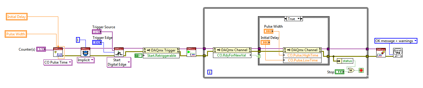
I use a mx-acquisition of data (NI USB-6211) and I would like to use it to generate a pulse of digital modulation
that is triggered by an analog input signal. The input signal is a pulse of squares analog modulated
What is almost periodic. It's because of my set up, and I can't do anything with it. I would use the
before the edge of this signal to trigger the production of a digital pulse signal modulated (0-5 V). My
problem is summarized in the figure given in the annex. I would also like to have the possibility of
Configure the 'backwardness' and the term of "TAU_LED", while the VI works.
I have looked at several examples of instrument OR meter generation, generation of PCI I / AO, but doesn't
not managed to solve my problem. Does anyone have an idea of how start with my problem? Are there
No matter what example VI that I could start to change?
Thanks in advance,
Gregory
Hi Gregory,
Sorry I forgot to mention: the Initial delay applies only to the first impulse of a redeclenchables generation. Every subsequent impulse will use low time as the Initial delay. I agree the behavior is not very intuitive (our latest guidance of series X actually supported an Initial period to allow on property Retrigger), but it is described in this knowledge baseand should also be mentioned in the DAQmx help.
As you generate just a single pulse, I would recommend simply connecting the Initial delay and at the entrances of low time to the same value for each pulse will be delayed further.
Exit tasks ongoing counter currently supports DAQmx writing. However, the finished generations or simple impulse are not. However, you should always be able to get the behavior you need with a property node DAQmx. The current solution on the series E/M is:
Again, this is not the most intuitive, but I checked that it works on my 6210. After writing a new value in the software the pulse will be updated on the 2nd trigger. Attached is the code stored in LV8.2.
Best regards
-
How to read the Serial Arduino data using labview VISA?
Hi =). Im a beginner work reading data series from an arduino but im facing... Lets do it step by step
I built a voltage divider circuit which gives from output
from 0 to 5V. The output of this circuit is sent to a 0 analog input pin
of a Committee of Arduino Duemilanove.(1) Firstly, I connected the cable to connect to my laptop USB the Arduino.
(2) I went to start-> control
Control Panel-> system-> hardware-> Device Manager. Check the Ports (COM
& LPT). In my laptop I can see USB Serial Port (COM4). Now I know only in
LabVIEW that I must read the data series COM 4.(3) to the side of the arduino, here's the code to read changes in voltage
entered to analog pin 0. The last line of 'delay' determines the sampling
Rate of how we want to taste the output of the voltage divider:int potPin = 0; Select the input pin for the output of the voltage divider
int val = 0; variable to store the value from the probevoid setup()
{
Serial.begin(9600) (9600); Opens the serial port, establishes the rate of 9600 bps data
}void loop() {}
Val = analogRead (potPin); read the value of the voltage divider
Serial.println (Val);
Delay (10);
}I slightly modified the basis series reading writing VI... I have
attached the block schema used with comments. Basically, I tried to read
data series, divide by 1023 and multiply by 5 to graphic voltage
variations of the voltage divider circuit. But Im not getting
the correct voltage output values. The value of the tension just keeps go
0 and coming again, as shown in the photo.Could you guys please guide me on what went wrong?
Thank you!
-you read the data, even if there is no data on the port. If 0 bytes are read => «»
-in the case of false, you resources VISA wired for the output of channel tunnel?
-There is no close VISA at the end of the VI resources
-you're not a loop this VI reading bytes
I added an addaption of your VI that you should give a try maybe

-
Hi evryone,
Im a beginner with Labview you know I can see a picture in my executable file. In normal VI I see, but when I debug him is lost. Ive tried to find some information on this problem but I've found nothing. Can you help me to smb. ?
THX tom
Dennis is right, you should use the 'path of this screw' primitive and change the path in regards to your insurance VI works no matter where the application runs.
-
Order of the blocks in LabVIEW
Hi all
I am a beginner in LabVIEW. I what is the order of execution of code in block diagram in LabVIEW. It is left to right or from right to left? or y at - it a preference for order as a priority higher than for loops or something like that?
Be a c programmer I think this way. Is it good to compare and understand Labview as well or is it a completely different architecture? Please correct my way to understand things if I'm going in the wrong direction as a beginner. I enclose an example of block diagram, perhaps you can explain with her
LabVIEW does not from left to right, up and down, forward/reverse or any other physical form on the block diagram. LabVIEW is a DATA flow programming language, and it is the movement of data that determines the order of execution. There is a section using LabVIEW called 'data flow programming model' that you should read. In the picture you posted, you will notice screw connected with their error in / mistake the son. These connections are often used to enforce the order of execution. Also, because of its Western heritage, entries are typically placed on the left side of a VI and exits on the left, then you will generally see VI placed from left to right but it's just for readability. If there is no data connection screws separated on the block diagram, they will be run in parallel.
Maybe you are looking for
-
Hoe kan ik in uitzetten spellingcontrole automatic?
Thunderbird has spellingcontrole aangevinkt, maar ik squeeze die niet weg vink.
-
USB8452 - how to set a clock of 20 MHz SPI Stream mode?
Hi allI can't really manage set a clock of 20 MHz SPI Stream mode. To set how often I use this property node (see image)[for example to set a 1 MHz clock, I put:] Wave1.TMNG.SclkLow = 50 (500ns)Wave1.TMNG.SclkHigh = 50 (500ns)] And everything works f
-
HP ENVY 17-n046nd: update of HP ENVY 17-n046nd memory
Hello Can upgrade you the memory of 8 GB to 16 GB? If so, how many slots memory this laptop there? Best regards Nick
-
original title: big problem - d3dxg_43.dll Hi Ive had problems several times for running some games of aand demos on my pc States d3dxg_43.dll - it is not present, install the file and try to run the Setup again
-
little blue horizontal lines on the doc, I've done the nozzel check and head cleaning.
All of a sudden one day when I print there are some blue horizontal lines on the doc, I've done the nozzel check and head cleaning. I have a 810