Compression of the sample
Hello
I have a scanner with the following configuration:
-Sampling rate = 20000000
-Lrecl = 12000000
It works very well so far and gives me a sampling time of ~ 600ms. Where the problem occurs is when I want to display the signal in a graph. Here, I get the error message 'insufficient memory '. That's why I used the express vi "compression of sample to reduce the data by a factor of 10'000 for example but this still does not work when I put the entrance of the"Fetch WDT.vi niScope"value"-1 "."
It works when I set this value to 1'000 ' 000 for example but is not a solution because I do not have the full signal until ~ 600ms! I also can't reduce the sampling rate of the digitizer because I will lose the precision of measurement.
How can I solve this problem?
Thanks in advance
Examples of NO-SCOPE contain examples of code explaining how to extract data from map of range into pieces (for example niScope EX Fetch in Chunks.vi). As mentioned above, there are tuturials on how to manage large sets of data to LabVIEW, one using LabVIEW and one here. Between these three sources, you have sample code to pick up your card brought into pieces, decimate for display and display without running out of memory. It's the algorithm and the method used by the NO-SCOPE Soft Front Panel.
Tags: NI Software
Similar Questions
-
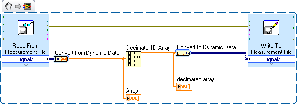
Make the sample compression in an already generated file .lvm
I have captured a huge amount of data in the file *.lvm. I want to make to the spreadsheet, but the data is too large to fit into a spreadsheet. in fact, I forgot to use a compression of the sample in the VI. so, how can I open the file LVM compression of the sample and then take the data set reduces to Excel?
I was thinking about something as simple as this:
Just read the lvm, decimate the table to purge unnecessary samples and then rewrite it in another text file.
-
Hi all
I need to re - sample a 1KH 1MH tdms file, it seems that it is possible with the help of "Sample Compression" but the point is the entrance to this block is a single signal and my tdms file consists of a few different channels a beginner I don't know how to get my file PDM signals and connect them as inputs to the block of "Compression of the sample!
I would really appreciate if someone can help me with some advice.
Thank you very much
Navid
Read your file TDMS using the open functions then reading PDM. Here you can specify the offset and length to read. You can then put this into a while loop get 1000 samples at a time stopping when there is an end of file error, or your reading returns less then 1000 samples. Take these samples of 1000 and get the average of them. Then write this single data point to the TDMS file as a new group. Then close the file TDMS times all 1000 pieces have been processed. Then you will have a file with the raw data in the existing group and decimated in the new data. You can also choose to save them in a new TDMS file but I find that to do this way because it would be all in one file.
-
How does Compression affects the integrity of the colors?
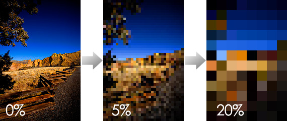
When the compression is not completely spoil the colors, it often simplifies the image and functionally Pixelation it.
The pixelated above image has the same balance of color than the other two.
So, how compression affects the integrity of the colors?
Think of an image as having two distinct layers: black & white, layer on which the color information are asked by the layer of color.
Bad compression also uses sampling poor color - aka color resolution - to record the size of the file. It will be the average of the values of two adjacent pixels of color to create a larger pixel of color avaraged. If it's REALLY bad--as in the video DSLR and HDV - it will average the colors of adjacent pixels of the average color pixels FOUR an even bigger.
And what do you think would make the integrity of the color?
-
When I try to buy a book, it seems it download but does not work. If I am able to get a sample & try to buy the sample goes far & no new book. There are funds in my account iTunes Help!
Mine just did the same thing. I've even went and was sold again in case I did something wrong the first time. Still no book! I had to happen a few weeks ago, but when I closed iBooks and reopened, the book was there. This time that didn't happen. I prefer to read on the iBook, but I'm not if my books download
-
Instruments of the sample of user-specific does not see EXS24
Logic Pro X 10.2.0 EXS24 sees the Instruments of the sample in my folder/library specific to the user, but only those in the global folder/library.
But Logic Pro 9.1.8 EXS24 can see both.
Background:
I had my mid-2010 27 "iMac running OS X 10.8.5 and Logic Pro 9.1.8 (as well as Logic Studio 7) I upgraded to El Capitan without incident. I bought and installed Logic Pro X on the App Store without incident.
The menu of Logic Pro X EXS24 instruments shows that the Instruments that are in the global folder:
Instruments of Macintosh/Library/Application Support/logic/Sampler
The menu Logic Pro 9 EXS24 instrument shows the Instruments that are in both aggregate AND user-specific folders.
The menu instrument show the structure of:
Instruments of Macintosh/Users/me/Library/Application Support/logic/Sampler
It adds an entry listed as 'Factory' under which it places the Instruments found in:
Macintosh/Library/Application Support/logic/Sampler instruments.
If I load a project in Logic Pro 9 that uses some of the Instruments found in the user-specific directory in Logic Pro X, Logic Pro X reports errors that he cannot find the instruments and gives no possibility to 'find' and opens the project with a bunch of sounds of the sinusoid default loaded instead of the missing instruments.
You can see two directories with the Global Directory on the specific to the user on the right and the left in my attachments.
I have also attached a picture of the EXS24 Instrument Menu in Logic Pro 9 and Logic Pro X.
Any guidance would be greatly appreciated.
Thanks in advance!
Here is the Menu of EXS24 Instrument under 9.1.8

Here's the EXS24 Instrument menu under 10.2.0

Here is a comparison of the Global Sampler Instruments on the left directory and Sampler Instruments menu specific to the user on the right
(The view is provided by PathFinder rather than Finder which allows the sidebyside view)

1. it is always useful to search the existing threads here at discussions.apple.com. Try some different keywords, and you can often find other people with similar problems.
2 check out this thread. I had a similar problem and solved, answered my own question.
X - Exs24 folder 'instruments' lacks logic
3 re-indexing loops Apple Loops * should * help to find the folder. Here is some info on this:
4. you can also try simply to drag the folder (in your Finder) and a session logical X. This * should * the entire folder to the index for you.
5. you can always move the folders in your ~/Library (user) indexing question in your corresponding library/library/library indexing (root) folder.
-
reading of the sampling frequency of the NI9862
Hi all
I use a DAQ chassis with modules 9205 (analog input) and 9862 (NOR-XNET CAN).
I have a program to synchronize the modules for acqustion based on the attached example. My question is how to determine the rate at which data comes the 9862?
It seems to be double the rate of the 9205 when I set the sampling rate for the 9205 to 500 Hz.
Is there a property node or a method that I can use to find the rate? I looked in the manual, and it gives no information.
Thank you
Griff
griff32,
Baud rate XNET CAN occur in your database. You can also check using a property node. In the example, in the XNET Session property node, you can develop, select the Interface > baud rate. You can do a right click on it and change it to read and son in an indicator.
Alternatively, you can write to this property node to replace the transmission speed in the database. Baud rate must be compatible with the speed of your network. It also has a max of 1 mbit/s. If you want both to acquire the same amount of data, I would recommend changes in the rate of the analog input task or samples to read through.
-
cwdsp. Sine wave is where the sampling rate?
Hello
According to the method above (CWDSP. Sine wave), the parameters are the following:
(n, a, f, Phase)
n As Variant - [Input] number of samples to generate.
Amp as Variant - [Input] Amplitude of the signal that results.
f As Variant - [Input] frequency of the signal resulting in standardized units of cycles/sample.
The phase as a Variant - initial phase [output] in degrees of the generated signal. Output, the Phase is the phase of the next portion of the signal. Use this setting in the next call to this function to simulate a generator of continuous functions.We are not lack of sampling frequency?
example:
I want to generate the next sine-
FREQ = 1 kHz
sampling frequency = 10 kHz
(Number of samples) block size = 1024
Amp = 1
How will you use this function for this signal?
I think (but I'm not sure of it...) is: CWDSP. SineWave (1024, 1, 1/10, 0)
There is an example: "power spectrum". In this example, they do not mention the sampling frequency and the signal is generated as follows:
CWDSP. SineWave (1024, 1, 0, 1000/1024)
No mention of the sampling frequency.
Thank you
Hey Rafi,
Both of your assertions are correct. The frequency of de.1Hz at no time is the equivalent of what you would get from sampling equipment of a wave of 10 kHz to 1000 s/s; in both cases, you will see a cycle of the wave every 10 samples, as you are pointing out.
-
display the values of the sample on a graph
Hallo!
I have a problem with a graph, the thing is that I really showed values of Y of the samples on a chart. There is a possibility to make a comment (as in attached photo) but I need the waltz instead. Any ideas? Thanks for the trouble,
Greetings!
Dear Aleph.ka,
Here is an example of what you might need. For more documentation, please refer to the description of the node property applied (Annotation list):
http://zone.NI.com/reference/en-XX/help/371361H-01/lvprop/waveformgraph_annot_list/
I hope this helps.
Kind regards
-
DMM (NI 4070), how to correctly set AC Freq (bandwidth) by the sampling rate
using a NI4070 multimeter and I see the max connection is 300 kHz by respect it. But I don't understand how to set the min and max, acFrequency according to the sampling frequency or speed reading.
6 1/2 digits resolution, the speed can vary from 0.25 s/s to 100 s/s and this range corresponds to a lower end on the connection (minimum acFreq) from 1 Hz to 400 Hz.
(Q1a) - is the playback speed, controlled by the minimum setting of IviDmm_ConfigureACBandwidth? or vice versa?
Otherwise, I do not see how to control the rate of reading or the sampling frequency. IviDmm_ConfigureMeasurement only allows you to control the range and resolution.
(Q1b) - is there a way to directly control the sample rate (digitizer) or playback speed (dmm)?
(T2) - the upper limit of the bandwidth of AC always seems to be at 300 kHz... is there still a reason to reduce this maximum value?
(T3) - Finally, unlike the traditional niDmm function, the resolution via the IVI configuration should be passed as absolute value; does directly when number of digits and the beach? For example if I want to 6 1/2 digit to 300V range, I guess that by the specifications that the resolution should be set at 0.001 V... followign, if I want 5 1/2 digits to 1V range, the resolution should be set to 0.00001 V?
Hi Rjohnson,
I'll try to answer your questions as best as I can:
Q1A. The ConfigurACBandwidth function is used by the driver OR DMM to calculate the good aperautre for the measure. So yes, by adjusting your minimum frequency, you will affect your reading speed.
Q1B. Your reading rate will depend largely on your measuring cycle. To get a fast measuring cycle, there are a few things that you can adjust. You can programmatically control your time aperature, as well as your time to settle.
Q2. I can't find a reason to change. This parameter is only used for error-checking and verifies that the value of
This setting is less than the maximum frequency of the device.Q2B. I think what you say is right, but I'll need to check on that - I'll let know you as soon as.
Hope that helps. "" "I would recommend checking the explanation of the Cycle of the DMM measurement in DMM help' devices ' NI 4070" DMM Measuments "DMM measurement Cycle.
Take care!!
-
Change the sample DAQmx and Terminal configuration mode
Hello
I'm studying 'Timing and synchronization features of NOR-DAQmx' from the following link,.
http://zone.NI.com/DevZone/CDA/tut/p/ID/4322
Could someone tell me how to Figure 2, Terminal configuration entry in the part "DAQmx virtual channel creat? Shoud I double-click on the icon to change it? Or there is some way that I can show it in the block as the sample mode diagram in the DAQmx part?
How can another question, in the DAQmx calendar part, I put "Continous Samples" here? It comes from the function palette? Thank you.
Hi Oly,
To make the configuration of senior year to enter the channel 'DAQmx create' you will need to create a constant or control over this VI either. When you hover over a VI, as the VI "DAQmx Create Channel", you will notice that the dots appear around the edge of the square. "" When you roll your mouse over these points, you mouse pointer will appear a coil of cable/wire how you can right click your mouse and select 'Create' constant ' or 'create' control '. If you create a control, you have a user control in your front, where as if you create a constant, you will have a drop-down list in your block diagram.
It goes the same for continuous samples, simply hover over the VI, right-click on the corresponding 'point' and select this option to create a constant.
In case my instructions are unclear, that I have attached pictures of how to go about doing this, the first is to show 'points' I speak around the VI and the second picture shows the possibility to choose after you right-click on the point.
Good programming!
aNIta B
Technical sales engineer
National Instruments -
Digital filter on the sample clock 6601/6250
Hello
I use a PCI-6601 (Dev1) and the card PCI-6250 (Dev2) connected via a cable RTSI.
I apply a PWM signal to the 6601 ctr0 (Dev1 / / PFI38) and activate the digital filtering (100 ns) on the respective task (measure of the period).
I apply an analogue signal to AI0 map of 6250. As I am interested in a sample of analog measurement when the PWM signal changes from low to high, I put the clock sample of the AI task source ' Dev1 / / PFI38 "and the side assets of clock sample"Insurrection. "
Everything works fine, but I have a question:
The sample for the AI clock is the task the filtered PWM signal or not filtered PWM signal?
Kind regards
Udo
Hi Udo,
Great question! Digital filters are actually not part of the subsystem of counter, but rather the line itself PFI. So, if you have activated the digital filter for a specific line of the PFI, the signal that you route to any subsystem of the PFI line will have already crossed the filter.
It's actually the workaround to the PFI filters on M-series / TIO DAQ devices when you are not using meter (materials of filtering on each PFI line but the DAQmx driver allows only the filtering part of duties of counter on these devices).
I also wanted to emphasize that the 6250 itself has 2 onboard counters, then you could do the same thing using just the 6250 (unless you use more than 2 meters). I hope this helps!
Best regards
John
-
Buffer the output AO, refresh rate is different from the sample clock frequency
Hello
I am an AO output in the buffer using a single channel. I have a stamp with a ripple of 200000 points with a triangular waves of a 1000pts each repeated 200 times. If I want a frequency of 1 Hz, I simply update this waveform 1000pts and if I wanted to 5 Hz, then 5000pts and so on. But there is some frequency that I won't be able to use like the refresh rate (the number of samples that I ask to update) is different from the sample clock frequency, which makes synchronization with the other difficult to trigger (incomplete cycle). Frequency 3 Hz (update 3000pts), as (update 7000pts) 7, 6 Hz (update 6000pts), 9 (update 9000pts)... 11Hz at 15 Hz and is not valid in the sense that the refresh rate is different from the sample clock frequency. That makes a whole lot of inaccessible CONFIGURED! Can someone tell me what determines the banned frequency? Is this something to do with the material?
concerning
One thing you can try is to change the number of samples per cycle. This cannot give the precise frequency accurately, but can reduce the average error.
120 Hz, the error is currently about 400 parts per million (ppm). The accuracy of the time base is 50 ppm, then this error is less than 10 times the inherent error due to the time base.
Consider this configuration: the closest nominal sampling you rate, you can get is 120048 Hz (1000 samples per cycle at 120 Hz). If your buffer contains 1200 samples per cycle, 100 copies of it would produce 1 second of data to 120,048 Hz. But if the buffer contained an average of 1200,48 useful Samper by cycle, you get the exact frequency. Of course getting 0.48 of a sample is delicate. But the kind of feasible. If you use 48 cycles in the 1201 samples per cycle and the cycles of 52 to 1,200 samples per cycle, the total number of samples per second = 120048. Average frequency will be exactly what you want. Instantly, the frequency is slightly higher or lower than the exact value. By an alternation of 1200, 1201, 1200, 1201... 1201, 1200 100 cycles that the Jig is fast. If you group all 1200s whole and all 1201 s frequency hopping may be more sensitive. If this kind of jitter is acceptable depends strongly on what you do with the release.
This technique is used in some systems of frequency synthesizer.
Lynn
-
How to specify the sampling frequency? Must use "measurement & Automation Explorer '?
I use to measure the input current analog OR cDAQ-9171 (chassis only location USB) and NOR-9207. I have 2010 NOR-installed DAQmx and LabVIEW.
How can I specify the sampling frequency?
If I use M & A Explorer to create the task, I can specify the flow rate (Hz) on the Configuration tab-> sync settings.
For the acquisition of data NOR, it is mandatory to use M & A exploring?
If I don't want to use M & A Explorer, how can I specify the rate (Hz)?
Hello
You can specify the sampling frequency with "DAQmx Timing.vi" located in the function palette DAQmx (read context-sensitive help on how to use wisely).
You do not have to use M & A exploring (MAX) to create a task.
A simple and quick way is to use DAQ Assistant (same configuration as in MAX) to configure your measurement.
Another is to use blocks of DAQmx function to manually build your application code.
In my experience Assistant DAQ is ideal for simple tasks (one measure), with regard to the more complex measures (synchronized the analog and digital inputs).
I tend to use function blocks because they give you more freedom about code execution.
Note: You can also build DAQmx code from a wizard configured DAQ task.
Best regards
Matej
-
Specify the samples only to change?
No doubt a variation of this has been requested before, so my apologies, but I'm unable to find anything.
I use a PCIe-6537 and try to generate a long sequence (say 2 seconds) using C. Is it possible to only specify some samples? Or do I need to specify the value each time the sample?
For example, suppose I want 32 track 1 followed by HIGH microsecond of a second BASS, repeated twice. I wish I could say:
Example 0: 2 ^ 32-1
Example 1:0
Sample of 1000000:2 ^ 32-1
Sample 1000001:0
However it seems I have to specify the actual value at each point in time. Of course, it takes much more time and memory to write but I do not see otherwise. Is there a way?
I hope that the question is clear. Thank you.
I can't find a place to change the theme or mark it as solved
My real scenario was a bit more complicated, but I found away around him. Each writing sample explicitly should no longer be a problem.
I hope that is correct on the occasion of my own post as a 'solution '.


Maybe you are looking for
-
High temperature HDD on Satellite M100
Hello! I have a high temperature 50-53 C (Hitachi, 100 GB) HDD in my Satellite M100. The temperature is controlled by Everest and HDDlife. Is this OK such high temperature?As for me, I think it's too high, because the drive HARD Hitachi 55 C the maxi
-
Why used the pc would I delete the songs of m USB?
I plug my USB and I opened the island usb and I want to delete some songs and when I right click delete it... the delete icon is not visible... Whats up with that?
-
Installation for Officejet 4500 disk crashed in Acer Aspire E1-571
I have a laptop Acer Aspire E1-571 with Windows 7 64 bit and has recently purchased the officejet 4500. I used the disc that came with the printer to install the software and during this process, an error box emerged which didn't say anything other t
-
I get this BSOD a few fair times now when I try and shut down the computer, just after it is just about complete stop this BSOD appears and the Pc reboots and I must continue to press stop until they stop the BSOD. IV ' e attached here the dump files
-
BlackBerry Smartphones with e-mail send only
Never, I don't want my Blackberry to receive all e-mails. I would like to occasionally send. Is this possible? If this is not the case, is there a software download that should allow? Thank you Warren Edward