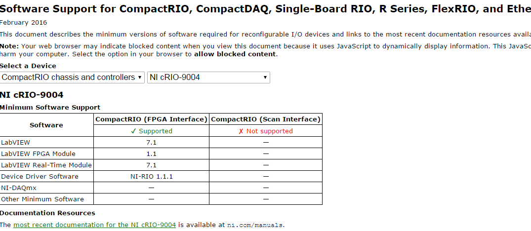
cRIO-9004
I have configured my cRIO 9004 with the chassis to my PC. But with the acquisition of data assistancce, I am unable to acquire data.
What can the reason for this possible?
Hey, Vinayak,.
The VI of Express Assistant DAQ uses the DAQmx driver and will communicate only with devices supported by DAQmx. (Devices like CompactDAQ, DAQ, of the series M and X series DAQ USB or PCI)
CompactRIO is an incredible product, but it's much more complicated program. You will need to add it as a remote device to your project and specify at least one additional VI to run on the processor in real time (if not a third run on the FPGA).
Google image search "getting started with compactRIO" for a starting point.
Tags: NI Hardware
Similar Questions
-
I tried to compile my cRIO-9004 with local server.but he showed me the message that XILInk 10.1 installed.
But I have installed all required software in my ncRIO using OR max.
What is the reason for the problem?
Thank you
The software error complains is running on your PC, not the cRIO. This is a separate installation of the regular installation of RIO/RT/FPGA. I think that's what you're missing:
http://www.NI.com/download/LabVIEW-FPGA-Module-2014/4842/en/
It is 1.6 GB, so it won't be a quick download. Let us know if that fixes the problem.
-
Compliling VI in LabVIEW with cRIO-9004 controller and chassis cRIO-9104
I tried to compile in LabVIEW with cRIO 9004 and cRIo-9104 connected.
It has three options
(1) use the server local compilation.
(2) to connect to the network compile Server
(3) to connect to the service of LabVIEW FPGA cloud compile
But I'm unable to compile my program using one of these.
How can I get my compilation made? Help, please.
Thanks YouCp
Service provider shared's Standard Service program is an annual fee of NOR, which in turn allow you to update your modules and LabVIEW and benefiting from the support of NEITHER.
-
Thus, Ive played with a cRIO-9004 with FPGA. But there is a problem, whenever I place a node FPGA of e/s on the block diagram that it does not work.
It emits a signal null and says this in the context-sensitive help "LabVIEW does not support the I/O nodes in the my computer application instance.» Place the knot on the block diagram of a VI that is open under an appropriate target in the Project Explorer window. »
I do not have it in the instance of my computer. I have done before with a sbRIO and followed similar steps. I've never had this problem with the sbRIO.
Any ideas?
Under your main project you need to have added a 'target of cRIO' under this goal, you must have added a "chassis cRIO. And then udnerneath the chassis, you need to have added a "target FPGA. Finally, you place your VI within the 'FPGA target' in the tree structure. To add something, usually a right click on the element it will give you the ability to add-> target or something similar.
-
CRIO-9004 OR not no projection in MAX
Hello! It's my first time to use cRIO-9004 and problems already beacause the controller is not displayed in MAX. Is this supposed to show under remote systems? The following entries are installed in my PC, please let me know what else I'm missing.
LV 8.5.1
NOR-RIO 2.0
Thank you!
-
Change the ID of standard to extended in the NI 9853 module with cRIO 9004
Hi, Im new to the cRIO system (9004) and the module NI 9853 (CAN high speed); Ive been able to successfully use the example of "CAN basic.vi" in my project to transmit via port MAY 1 and 0 listening port on the CAN (because my cable and everything seems to work fine). I also have a prototype CAN network made some microchip circuits (decks try to work with dsPIC30F4011 and MCP 2551), I know that my prototype CAN network works because Ive tested, and devices thereon are able to communicate.
When I try to hang the cRIO with NI 9853 as new lymph nodes to the network nothing happens, Im not able to read or to convey to all the other nodes in the network with the example of VI.
When I plug the cRIO to the network I have disable CAN 1 port and just change the FPGA at the exit node CAN 0 (as indicated in the description of the example) to be able to transmit and to read more from the port 0, but nothing seems to work.
Anyway, on my prototype network devices use extended (decimal) IDS, I know that on the example of the cluster of uses of identifiers in hexadecimal, but I don't know what specification they use (2. 0 to or CAN 2 0 b). So Im trying to figure out what point, to see if this has something to do with the problem.
In advance... Thank you
I'm not sure that this will solve your problem, but at least you should take care about the 30 bit that is used by OR identify IDS of arbitration standard or extended.
See the results of research for the scope id may 30 bits.
-
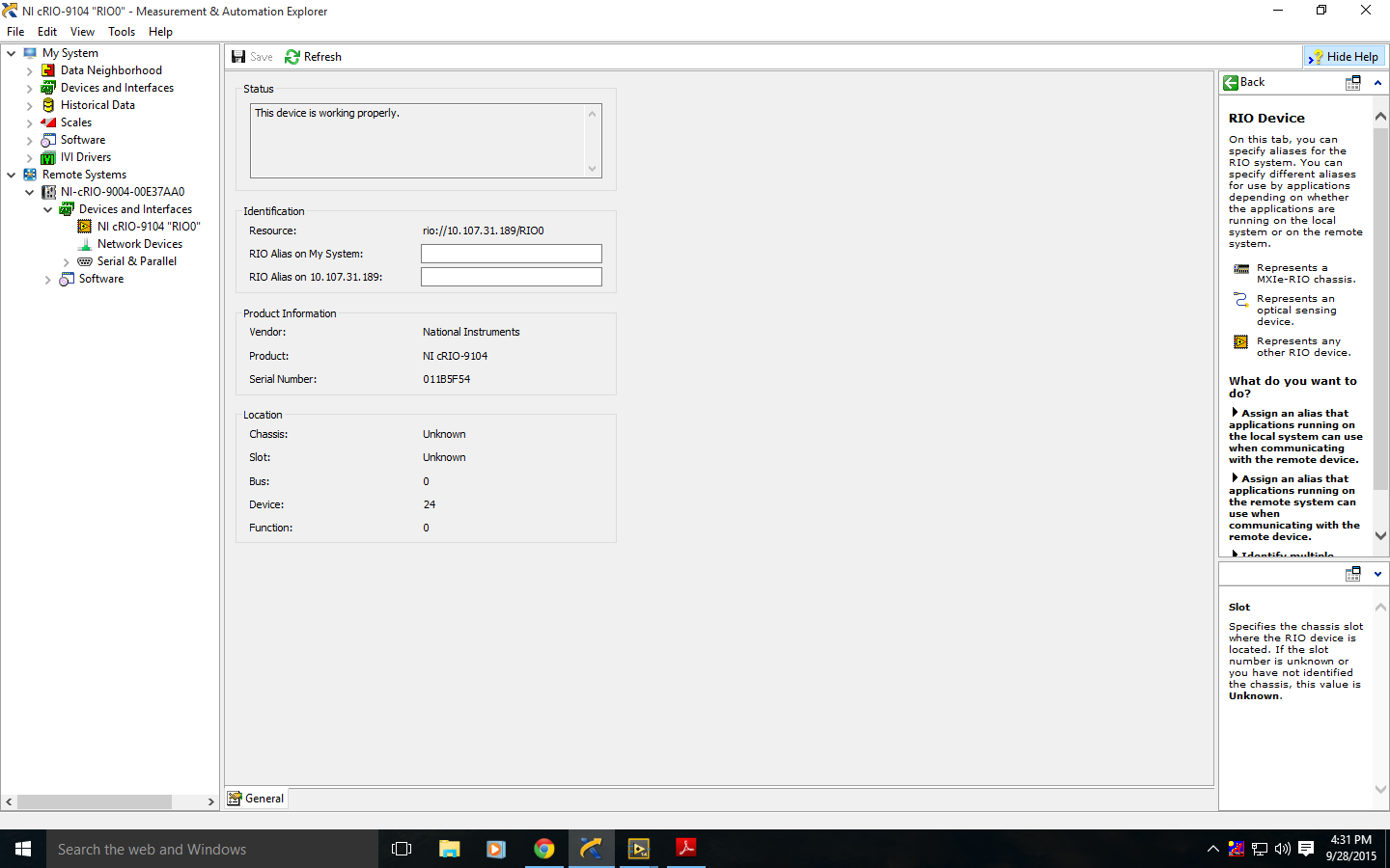
facing problem in communicating with chassis cRIO-9104 NI Max
I tried to communicaste with my cRIO-9004 using the ethernet cable that is connected to the same subnet as the PC master. It is mounted on the cRIO-9104 chassis that has a reconfiurable FPGA and 8 slots.
But I could not find cRIO-9004 in the specified window NOR MAX chassis as unknown.
I am new user of this module and the software. Help, please
Hey, Vinayak,.
I'm not sure that there is a problem here. Usually, you'd do anything with Max modules are you able to add them to your project in LabVIEW?
-
Hello
I - labview 2011,-LVFPGA in real time-, - NIRIO 4.0, cRIO - mdk 2.0 and cRIO module - support 4.0.1...
I work in the construction of a new module of m... first of all, I want to control the slots on the frame... So, I run, software part of that
application ==> http://zone.ni.com/devzone/cda/tut/p/id/7868
and it works... I see the signals on my oscilloscope...The problem is that I couldn't find a way to add the generic module to my own FPGA project...
I also study the sample application by giving this link ==> http://zone.ni.com/devzone/cda/tut/p/id/4539
and you see it add the cRIO-generic module in embedded project.Here's my way
* I m creating an empty project and add cRIO-9004 by > right click (Project) > New > target and devices > time real compactRIO > cRIO-9004
* and then, good click target FPGA (cRIO-9103) > New > C Series Modules > new target or device > C Series Modulebut I couldn't see the module "generic"...
What I m missing?
I had the same problem. Arise in 2009, but not 2011. See this:
I added the line "cRIO_FavoriteBrand = generic ' in the ini file." He now appears less 2011.
-
using slots chassis for general use cRIO
Hello
I have cRIO-9004 and cRIO-9103 Chassis, labview 2011...
AFAIK, the cRIO chassis controls its slots if it present any module or not... If someone detect read EEPROM and so on...
But how can I control the slots on the frame cRIO for my own general use without any module...
When I create projects, it shows me just like I/O chassis
* chassis temperature
* LED FPGA
* Scan clock
* Sleep
* the system reset
I couldn't write anything of chassis slots and see to the oscilloscope screen, (for example: using a digital or analog output)...
Didier...
Try to follow the steps, you will create a new module. As in this example, but skip the part of the circuit.
-
In time real CRIO - writing a file on a PC hard drive
Hi all
I am developing and application with the following hardware features:
Time real cRIO 9004 target device
HAVE cRIO 9205
AO cRIO-9263
and the following programming features:
I run an FPGA VI to establish PID control where the reference signal generated in the FPGA and the real is an acquired signal through the cRIO 9205. I also find target FPGA FIFOs host in order to pass the data from the FPGA to the application of the RT. The time real VI will run in the 9004 cRIO processor. Now, with the data from the FIFO I would write a file (regardless of the extension), in order to do more tests. I did it but I don't want to use the local memory of the RT, instead, there will be a PC (hard drive) where I can place the file in order to write it (with data). I'm not able to do so, as 1) I don't know how to call the PC hard drive and 2) I don't know what communication protocol fits better I want to develop a device to Windows Welcome.
Nobody helps me?
Thank you very much
Enrique
The cRIO-9004 unfortunately has USB, so you can not write on a USB Flash drive (which would be my first suggestion). If you want to store the data on the host PC, you will need to write a simple TCP/IP client/server to send data to the host through TCP so that the host can receive and save to disk. Façade of the VI may seem as it is running on the PC, but it's actually just show you data be listened to the target (you are not allowed to piggy-back on this same Creek).
There are several examples of TCP/IP client/server integrated into LabVIEW.
-Danny
-
Is possible to Interface in Mode Scan in NI 9004
I have NEITHER cRIO-9004 and I want to have a demonstration of how it will be used with different modules so I want to use scan mode to the point of the demo program interface, but I don't see Scan mode press the software that are available in NI MAX.
EDIT
However this 9065 cRIO is a good value and the 9004 is almost obsolete
-
I use a cRIO 9004. I noticed it has a chassis temp option. I was wondering if there was a way to find the input voltage. My unit is battery powered and I knew my batery voltage level. I'm doing some kind of a voltage drop detector.
I am a novice to Labview - I'm sorry if I missed something obvious.
Thank you.
You have not forgotten anything. Currently, there are no i/o chassis set up to read the voltage on your power supply. You'd have to do is to use an analog input module to read the voltage yourself.
Kind regards
-
Why do I get error 66 with cRIO and STM library after 6 hours
I have a RT (for the cRIO-9004 controller) software and a host software (on my development computer) which Exchange data through the STM library. Everything works fine, but after about 6 hours, the host stops with a message 'error 66 in STM Read Msg.vi'. Why does this happen? I use LV 8.2 and the STM 1.0.32 library.
Thanks in advance.
Hi all,.
would it not possible to send your project RT together in order to test it. Make sure that the SubVIs are included. Thank you! Perhaps one of the possible reasons for your error is that your VI uses 100% of the capacity of the CPU for communication over TCP/IP breaks down due to a leak of resources, because the priority of the screw is higher. Check the use of the CPU resources when running.
Concerning
Greg
-
When you try to run a VI that if interface with cRIO I get code error-63191. My cRIO is connected to my computer via an Ethernet cable, the cRIO and mobile LAN are the same IP address. The Project Explorer and MAX are able to detect the cRIO. Project Explorer is able to connect and to deploy.
I tried to change the IP address in the 168.192.0.11 to 168.192.0.10 Project Explorer as the cRIO-9004 element is connected to the title of the first IP address, Project Manager (which seems to serve as an interface with the cRIO-9103 component) may be intellectual property conflicts. I end up getting a different-63040 error code.
The first error screenshots are attacted and MAX and connection project manager
Hello WheelchairDev,
On this screenshot you just sent to the course, it seems that you do not have your project set up properly. You should have your project-> cRIO target-> cRio-> target FPGA chassis.
If you want to see an example of this, of the LabVIEW startup window, select the FPGA project in the drop-down menu of targets to create a sample project.
Once you change the layout, let me know if you have any other questions.
-
cRIO, FPGA, portability to different configuration of module e/s
Hello people!
For my research project, I need support.
I have to implement the NO-tutorial: "CompactRIO Control Design and Simulation Tutorial" on different hardware.
My cRIO-9004 is no problem and the NI9104 chassis is the same.
Occure in problems with the config of the i/O-Modules:
Tutorial-config: Slot5 = NI9505, Slot8 = NI9221
MyDevice-config: Slot1 = NIcRIO-9215, Slot2 = NI9263, Slot3 = NI9217, Slot4 = NI9474, Slot5 = NIcRIO-9423
I think that there should be a smart way to port this programm for a different config and change the I/O-link with another module without neckshoot the programm. do not know how, because I am a newbie of LabView.
your ff
Hi ffelix,
The tutorial works with a 9505 (H-Bridge for Servos) movement Module and a Module of the 9221.
In your configuration, you HAVE some, a zone of OCCUPATION, an RTD, a DI and a Module, but none Module movement to control a Servo.
So if you plan to do a similar Assembly, you must use the AO Module or a Module (PWM) with an external driver circuit to control a motor. And rather than use the software NOR Motion, which I think is used in the tutorial, you will need to program the motor by yourself from scratch part on.
Christian
Maybe you are looking for
-
Delete links or anything like that of the Favorites?
How does one remove links or anything of the Favorites?
-
I've updated my iPad 2 and had to enter a new access code and password that I had already deleted the need to keep these incoming. After lunch, I went back to the iPad, but of course we must access code and password that I was wrong. I tried again an
-
I can see my xbox on my computer but I can't connect to the internet. I don't know what to do
-
Virtual Blu Ray player or Blu Ray drives external programs... Which one? Myth or Muffin?
Greetings one and all, Alrighty then let me are the sitch. When I bought my computer two years ago I got to worth the money, cash, dough or dollars to buy, so I had to skimp on what I wanted. The main thing I have the proverbial axe was the disk/driv
-
We have a 12 c ODI architecture using a dedicated server of 12 c of WebLogic running a J2EE agent and a DB of the ODI repository server. For this we have a warehouse of data on a separate server.We need to run commands to move, copy, compress and pre