FPGA issues on cRIO-9004
Thus, Ive played with a cRIO-9004 with FPGA. But there is a problem, whenever I place a node FPGA of e/s on the block diagram that it does not work.
It emits a signal null and says this in the context-sensitive help "LabVIEW does not support the I/O nodes in the my computer application instance.» Place the knot on the block diagram of a VI that is open under an appropriate target in the Project Explorer window. »
I do not have it in the instance of my computer. I have done before with a sbRIO and followed similar steps. I've never had this problem with the sbRIO.
Any ideas?
Under your main project you need to have added a 'target of cRIO' under this goal, you must have added a "chassis cRIO. And then udnerneath the chassis, you need to have added a "target FPGA. Finally, you place your VI within the 'FPGA target' in the tree structure. To add something, usually a right click on the element it will give you the ability to add-> target or something similar.
Tags: NI Software
Similar Questions
-
I tried to compile my cRIO-9004 with local server.but he showed me the message that XILInk 10.1 installed.
But I have installed all required software in my ncRIO using OR max.
What is the reason for the problem?
Thank you
The software error complains is running on your PC, not the cRIO. This is a separate installation of the regular installation of RIO/RT/FPGA. I think that's what you're missing:
http://www.NI.com/download/LabVIEW-FPGA-Module-2014/4842/en/
It is 1.6 GB, so it won't be a quick download. Let us know if that fixes the problem.
-
I have configured my cRIO 9004 with the chassis to my PC. But with the acquisition of data assistancce, I am unable to acquire data.
What can the reason for this possible?
Hey, Vinayak,.
The VI of Express Assistant DAQ uses the DAQmx driver and will communicate only with devices supported by DAQmx. (Devices like CompactDAQ, DAQ, of the series M and X series DAQ USB or PCI)
CompactRIO is an incredible product, but it's much more complicated program. You will need to add it as a remote device to your project and specify at least one additional VI to run on the processor in real time (if not a third run on the FPGA).
Google image search "getting started with compactRIO" for a starting point.
-
Compliling VI in LabVIEW with cRIO-9004 controller and chassis cRIO-9104
I tried to compile in LabVIEW with cRIO 9004 and cRIo-9104 connected.
It has three options
(1) use the server local compilation.
(2) to connect to the network compile Server
(3) to connect to the service of LabVIEW FPGA cloud compile
But I'm unable to compile my program using one of these.
How can I get my compilation made? Help, please.
Thanks YouCp
Service provider shared's Standard Service program is an annual fee of NOR, which in turn allow you to update your modules and LabVIEW and benefiting from the support of NEITHER.
-
CRIO-9004 OR not no projection in MAX
Hello! It's my first time to use cRIO-9004 and problems already beacause the controller is not displayed in MAX. Is this supposed to show under remote systems? The following entries are installed in my PC, please let me know what else I'm missing.
LV 8.5.1
NOR-RIO 2.0
Thank you!
-
Change the ID of standard to extended in the NI 9853 module with cRIO 9004
Hi, Im new to the cRIO system (9004) and the module NI 9853 (CAN high speed); Ive been able to successfully use the example of "CAN basic.vi" in my project to transmit via port MAY 1 and 0 listening port on the CAN (because my cable and everything seems to work fine). I also have a prototype CAN network made some microchip circuits (decks try to work with dsPIC30F4011 and MCP 2551), I know that my prototype CAN network works because Ive tested, and devices thereon are able to communicate.
When I try to hang the cRIO with NI 9853 as new lymph nodes to the network nothing happens, Im not able to read or to convey to all the other nodes in the network with the example of VI.
When I plug the cRIO to the network I have disable CAN 1 port and just change the FPGA at the exit node CAN 0 (as indicated in the description of the example) to be able to transmit and to read more from the port 0, but nothing seems to work.
Anyway, on my prototype network devices use extended (decimal) IDS, I know that on the example of the cluster of uses of identifiers in hexadecimal, but I don't know what specification they use (2. 0 to or CAN 2 0 b). So Im trying to figure out what point, to see if this has something to do with the problem.
In advance... Thank you
I'm not sure that this will solve your problem, but at least you should take care about the 30 bit that is used by OR identify IDS of arbitration standard or extended.
See the results of research for the scope id may 30 bits.
-
Mode of scanning/FPGA for a CRIO by Veristand
Hello!
I have a small error using my CRIO 9081 use with CAN communication, here's what I did:
1. I use the CRIO with scan mode and customized it "Scan engine" and Ethercat for show my analog modules under VeriStand, it's ok
2. I use the CRIO with FPGA Scan interface (together under Labview) to detect my modules CAN, also ok
3 - then I wanted to see the CAN and analog modules, so I use this page:
http://digital.NI.com/public.nsf/allkb/0DB7FEF37C26AF85862575C400531690
And here's my problem:
with this method I am able to see the two modules with the custom device 'analytical engine and ethercat", which is really nice, BUT, impossible project VeriStand, the error message asking me to turn the chassis using FPGA, but then I lost the analog module...
So is it possible to run a project Veristand using both Scan and FPGA interface mode?
Thank you very much

Hi Vincent,.
When you tried to implement, you use the procedure described in the following document in the section use of Scan Engine and EtherCAT with NI 986 x custom device modules XNET ?
From what I remember, because you use a cRIO-9081, you will need to compile an empty bitfile for your target and place the controller in Mode FPGA hybrid mode on your chassis.
Could you post a screenshot of the error of deployment, you see?
-
How to use the modules of the series and two different bitrates in FPGA mode on cRIO 9075
Hello
I have a project with modules namely NI 9227 (module 1) and NI 9234 (2 Modules)
The project is running and I use the file writing PDM and found that two channels is in the TDMS file while I download the file using FTP the cRIO.
1 - my quesition is the addition of a second rate in the FPGA?
2 - Why is it TDMS connect 6 channels and 4 channels?
Thank you
Attached to the project with two screws
Hello Ihab,
Sorry for the late response here; just saw this message! If you want to keep synchronized modules then definitely stick with the master configuration and slave for your two modules. Note also that you can taste a little faster with the NI 9234 as your master module (since its time base main internal is 13,1072 MHz instead of the time base of the 9227 12.8 MHz).
Also, see the tips and information in our troubleshooting guide for the synchronization of the series C with LabVIEW FPGA modules:
http://zone.NI.com/reference/en-XX/help/373197D-01/target6devicehelp/sync_acq_multiple_modules/
I hope this helps!
-
entry of the FPGA 9402 trigger cRIO 9064 on DIO does not read
Hello
I have a cRIO 9064 using the Module C 9402 as a quick DIO in a SCTL. I use it in a (GPDD) digital delay pulse generator.
I've successfully the GPDD, triggered by a square wave generated internal, clocked at 1 MHz.
and I measure the pulse output perfect on an oscillascope.
My implementation is actually a clone of in: http://www.ni.com/example/31131/en/
However, when I try to trigger from an external 1 MHz, 6 Volt amplitude; duty_cycle 50%, square entering the DIO3 wave
There is no trigger, as seen on the Ticks_Between_Trig - which should be around 40, when it is correct release.
I used the method "Check status" to make sure that the 9402 is ready before the SCTL.
(Note: although it is labled Mod3 in the screenshot, it is actaully Mod1 and it simple namign incompatibility - which, once set doesn't change anything.)
I see not all digital HIGH when the input trigger control, what I do when you use the internal trigger.
The LED flashes, quite often even if actually at 1 MHz.
My question is what thing I must have the DIO 9402 read the input signal.
I followed the instructions here:
http://zone.NI.com/reference/en-XX/help/370984R-01/criodevicehelp/cRIO-9402/
but maybe I missed something.
Thank you
Michael
Resolved,
I had a bad input pulse generator which was flacky.
When I check the amplitude of the pulses on an oscilascope but a day later, when I corrected my code to include the ready method of Module C.
the amplitude of impulse was not working, but I've always tried to test with her.
Finally I double checked on the oscillascope again the trigger signal to find not suffecient.
Old eqiupment... then the warm-up does not.
Michael
-
Try to compile some simple FPGA screws in my myRIO, but often get the error attached to the compiler. I got parts of vi works temporarily by manually of programming everything from scratch again (without copy - paste other vi), but now the simplest things (two while loops, one with e/s FPGA node with node of property of FPGA, stuff really really Basic) also give this error. This is getting frustrating. What I am doing wrong?
Best regards
Soeren
Hi new ppl
Now I came with a 'solution '. It turns out that if I create a new vi and manually (.. Yes manually) start placing blocks and make loops I can actually compile the FPGA vi. Sort of loops to copy - paste from one to the other vi makes a malfunction.
If someone else have experienced this?
.. .anyway to programming
Soeren
-
cRIO-9118 FPGA and or cRIO-9022 RT.
Hi all.
Having trouble to get my design FPGA compile for the target.
The error is the overuse of the DSP blocks. 64 available on target...
Do I have to reduce to a minimum the number of blocks of multiplier?
Or can I somehow multiplex on DSP minimixe DSP multivariate use?
Thank you.
FPGA high speed multiplier Math must be set to LUT and not AUTO, because it will use DSP and not LUT car if there is too little of DSP.
This will reduce use DSP, but increase the use of LUT.
-
When you try to run a VI that if interface with cRIO I get code error-63191. My cRIO is connected to my computer via an Ethernet cable, the cRIO and mobile LAN are the same IP address. The Project Explorer and MAX are able to detect the cRIO. Project Explorer is able to connect and to deploy.
I tried to change the IP address in the 168.192.0.11 to 168.192.0.10 Project Explorer as the cRIO-9004 element is connected to the title of the first IP address, Project Manager (which seems to serve as an interface with the cRIO-9103 component) may be intellectual property conflicts. I end up getting a different-63040 error code.
The first error screenshots are attacted and MAX and connection project manager
Hello WheelchairDev,
On this screenshot you just sent to the course, it seems that you do not have your project set up properly. You should have your project-> cRIO target-> cRio-> target FPGA chassis.
If you want to see an example of this, of the LabVIEW startup window, select the FPGA project in the drop-down menu of targets to create a sample project.
Once you change the layout, let me know if you have any other questions.
-
FPGA. What tool xilinx for Crio-9022 & 9030
Hello. I will be compiling the programs of fpga on the Crio-9022 and 9030. You need Xilinx different compilers to do the task?
With the help of LV ver14
CRIO-9022 requires xilinxs 14.7 tool?
CRIO 9030 requires the xilinx tools vivado 2013.4?
Thank you
Yes, it's because of the different FPGA series located on the backplane of the 9022 and 9030 cRIOs. You can see this KB and this KBto see below why.
-
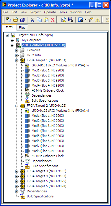
Many FPGA target as a controller cRIO
Hello!
I was reading the cRIO System Configuration Information (CRY) Encarta article (http://www.ni.com/example/51852/en/) and here the Figure 9 shows a cRIO controller with multiple FPGA targets. How can this be accomplished?
In my case, when I tried to add a 2nd FPGA target, under my cRIO-9076, I get a message that can only be associated with the controller.
Any ideas?
Support of claims library CRY to LabVIEW 8.5.1, which leads me to believe this screenshot was taken in this version. The RIO Scan Interface/FPGA Scan Engine (IRS) have been introduced in LabVIEW 8.6 and NOR-RIO 3.0.x. To include this support, introduced the notion of a frame in the LV (notice there is no chassis under the Comptroller in the screenshot). To facilitate the RSI and the analytical engine and provides a more accurate representation of what is actually available in a system, you can only add a frame by controller. This allows the IHR charge the correct controllers for deployment.
BT 8.5.1, you can add multiple targets to an integrated system controller/FPGA (as the cRIO-9072) even if there is no way that could happen in real life, so it's not really desirable. You can always do is to add multiple FPGA targets (even chassis cRIO) in respect of the purpose of the workstation in your project. Still allowing you to communicate with the target FPGA, but no screws will run on your PC system, not the cRIO controller.
-
cRIO, FPGA, portability to different configuration of module e/s
Hello people!
For my research project, I need support.
I have to implement the NO-tutorial: "CompactRIO Control Design and Simulation Tutorial" on different hardware.
My cRIO-9004 is no problem and the NI9104 chassis is the same.
Occure in problems with the config of the i/O-Modules:
Tutorial-config: Slot5 = NI9505, Slot8 = NI9221
MyDevice-config: Slot1 = NIcRIO-9215, Slot2 = NI9263, Slot3 = NI9217, Slot4 = NI9474, Slot5 = NIcRIO-9423
I think that there should be a smart way to port this programm for a different config and change the I/O-link with another module without neckshoot the programm. do not know how, because I am a newbie of LabView.
your ff
Hi ffelix,
The tutorial works with a 9505 (H-Bridge for Servos) movement Module and a Module of the 9221.
In your configuration, you HAVE some, a zone of OCCUPATION, an RTD, a DI and a Module, but none Module movement to control a Servo.
So if you plan to do a similar Assembly, you must use the AO Module or a Module (PWM) with an external driver circuit to control a motor. And rather than use the software NOR Motion, which I think is used in the tutorial, you will need to program the motor by yourself from scratch part on.
Christian
Maybe you are looking for
-
How to extract files on DVD VOB
I have many DVDs made from iDVD. The source of film is created from the FCE to QuickTime files. I did not save the Video_TS, VOB?, files. Can I extract these files from the DVD so I can use them for posting to YouTube, more editing, etc?
-
Palm Tungsten T3: palm tungsten T3
Hi guys, I have a Palm T3, which has all my calendar and Contacts for the past 12 years (it's my right arm) and it goes everywhere I go, it works normally for a few weeks out of the charger if it is not used much, but he must have died very quickly a
-
Hello everyone, I did my recall of batteries Iphone 5 but nearly full one year my iphone's battery the same boring thing. I would like to know for how long is the warranty new battery. Assuming that it is a new product, whereas 1 year, am I wrong? Th
-
BlackBerry Smartphones newspaper only Outlook synchronization
I'm new on the BBs, but I have difficulties to sync my Outlook calendar in the BB work log / calendar. I just want to sync the calendar and I'm happy to do it manually is to say by plugging my faucet to work via USB Tower. I don't want to set up a wi
-
Hello everyone. I am currently facing EasyCamera problem. I installed the driver for the camera on my Lenovo S205 (Windows XP Home SP3) and it works fine. Ditto on http://www.testmycam.com: camera work. The only problem I have is that in EasyCamera S