Current limit for analog output on USB-6211-OEM
The current output drive listed in the specifications of this card is of +/-2 my. What happens when you try to go beyond that? Is there damage to the card or is it simply rail out around 2mA. For example, if I connect a 1000 ohm load. I'm okay, if I have the output up to 2V (= 2mA), but what happens when I exit 3V with the same 1000 ohm load?
Thank you.
Protection of the overdrive is 2.4 mA, which means that you can ride this current without damaging the card, but a current of approximately 2 mA, tension is more guaranteed to be compliant to the specifications.
Kind regards
Brian P
Tags: NI Hardware
Similar Questions
-
Strange analog output of USB-6211
I just got USB-6211 to replace USB-6001 to set the clock to external sampling on analog output for LED lighting control. The part of external clock example works fine, but the analog output voltage is strange. To do self-monitoring, I connected control pin LED to AO0 & AI0 of surveillance in the NI MAX test panel and LED control on the ground at AO - GND & GND HAVE since I have both USB-6001 and USB-6211, I conducted tests on two of them with the same setting of wire. When I generate sine wave - 5V to 5V to AO0 (from NI MAX test panel), USB-6001 can monitor the same signal AI0, but watch USB-6211 - 3, 4V to 3.4V voltage truncated. I did the test separately (wiring one device at a time), so there is no interference between the two devices. USB-6211 past self-calibration and self-monitoring. Also, I did reset devices. I don't know why they would behave differently with the same configuration, and I hope that someone could help with this question. Thank you.
Hi skuo1008,
The USB-6001 can support + / 5 output current my from terminals to analog output, while the USB-6211 box can provide only +/-2 my current output. It is likely that the load impedance is too low, causing the 6211 to hit its current compliance and thus cut the tension. If you try to exchange your load with a resistance of at least 5 v/.002A = 2500 Ohms, you should be able to see the full +/-5V sine wave. I suspect that your DUT has a words 3.4V/.002A = 1700 Ohms impedance. You could use a device with higher output current or use a more current source buffer circuit. If you do not need a bipolar output, you might also consider using digital lines to control the LEDs.
Kind regards
-
Current limit for the PXI-4110
I'm a PXI-4110 with LabWindows programming. I'm trying the current limit. I have an output to 5V with a load resistance of 1 K; This makes the current 5mA. I put the current limit of 2mA to work. When I read the voltage and current is 5V 5mA. Here is my code:
g_voltageLevel_ch0 = 5.0;
g_currenLimit_ch0 = 2.0E - 3;
status = niDCPower_ConfigureOutputFunction (vi_4110_0, channel0Name, NIDCPOWER_VAL_DC_VOLTAGE);
niDCPower_error_message (vi_4110_0, status, errorMessage);
status = niDCPower_ConfigureSense (vi_4110_0, channel0Name, NIDCPOWER_VAL_LOCAL);
niDCPower_error_message (vi_4110_0, status, errorMessage);status = niDCPower_ConfigureVoltageLevel (vi_4110_0, channel0Name, g_voltageLevel_ch0);
niDCPower_error_message (vi_4110_0, status, errorMessage);
status = niDCPower_ConfigureCurrentLimit (vi_4110_0, channel0Name, NIDCPOWER_VAL_CURRENT_REGULATE, g_currenLimit_ch0);
niDCPower_error_message (vi_4110_0, status, errorMessage);I find that if I put my current limit to channel 0 to 10mA, above the error message disappears. However, I can put the current limit for channels 1 and 2 to 2mA, and I do not have an error message with them. I see nothing in the power supply on a valid range on the current limit. To be clear on what happens if I do this:
status = niDCPower_ConfigureCurrentLimit (vi_4110_0, channel0Name, NIDCPOWER_VAL_CURRENT_REGULATE, 8-3);
I get the error "Invalid value for the parameter or property."
However, if I do this:
status = niDCPower_ConfigureCurrentLimit (vi_4110_0, channel0Name, NIDCPOWER_VAL_CURRENT_REGULATE, 10th-3);
I don't get an error.
Channels 1 and 2 do not have this limit. I went down to 1mA on these channels and no problems.
-
The PCIe for USB 6211 OEM replacement
Hi you all,.
We want to change our design to use PCIe card data acquisition, since we had a few USB driver problem in the past. Is the PCIe-6321 a good match to replace the capture USB-6211-OEM card
Is there a better alternative?
Thank you
Fabrice
Hello Fabrizio,
Thank you for taking an interest in our line of PCIe cards DAQ. I took a glance at the USB-6211 OEM and PCIe-6321 to see if they are similar in specifications and capabilities. I would say the 6321 is a good match to replace your current USB card. As long as you intend to use no more i/o lines than expected or exceeds the designated sampling rate then it should be a good substitute.
If you need high speed sampling or more i/o lines for various tasks, then another card can better meet your needs.
The resources below compares several of our devices (USB and PCIe) X series.
What is NI X Series? -1. Presentation of the product
---
These links may also be useful during your upgrade:
Major differences between series E, series M and material X NI DAQ series
---
Guide to upgrade NI X series (USB to USB devices however)
---
Kind regards
Alex C. -
Incorrect value for analog output USB-6008. Cannot not out more than 3V
I use USB-6008 analog IO, but the analog output (AO0 or AO1) can go up to 3 - 3.5V. The output can follow accurately the value of 0 to 2, 5V, but then he start the values adjusted trolling and not can not spend you 3.5V exponentially.
The only strange thing the entire circuit is that I connected all patterns (analog source and I/O 5V) between them, but I don't see what affect the output.
Kind regards
ISSOKO
Thanks for the quick reply Ana.
It is not the Council NOR, nor the Council of motorization. Apparently, the interface for motor control (motor spirit C: solutions - cubed.com), load the analog output. A tension following actually isolated op amp output USB-6008 and solved the problem.
Best regards, ISSOKO
-
Reconciliation of analog output NI USB-6210
Using Labview, I am currently using an NI USB-6210 to produce a signal that a BOP of Kepco 50-2 M feeding programs. Unfortunately, this device NOR produced no analog voltage. Is it possible that I can use the digital output or against the unit OR to do something that approximates an analog output? I need a way to get the power output voltage has the supply to increase gradually in a predefined way. I only work with a couple of volts because of sensitive equipment, so accuracy is important.
I don't have access to the program at the moment so I don't know what version of Labview that I use, but I'll be able to check in a few hours.
Its probably not worth to use this device in a method not scheduled. Cheeper with analog outputs are available.
And don't forget the 4886 BIT card that can be purchased and hooked to your diet, there are even for using RS232 or GPIB device drivers to control the supply to
-
Digital magnification of output using USB-6211
Hello
I'm trying to use the example of LV "Cont writing dig port - Int clk.vi" to generate a model.
But I get the error-200077 on the sample clock. The popup error message suggests
using "we demand", but it doesn't have the choice with the DAQmx.
Any clue? Thank you.
It is correct. USB-6211 case doesn't have a digital time - analog base only. That's why the (63xx) X series cards are supported only for this example.
-
I use the outgoing/incoming analog DDK with the DAQ 6341 SMU map.
The examples, for example aoex5, show a single timer (method outTimerHelper::loadUI), but the example shows the DMA loaded with same size of vector data.
There is a comment in the outTimerHelper:
 call rogramUpdateCount, which implies that memory sizes different pad per channel can be used.
(the comment is: switching between the sizes of the various buffers is not used)
Nobody knows what should be the format the DMA buffer for data from multiple channels with different frequencies?
For example, we want a0 with a sinusoid at 1 kHz and a1 with a sine wave of 1.5 Khz. What looks like the DMA buffer?
With the same frequency for each channel, the data are interleaved, for example (ao0 #0, ao1 #0; ao0 ao1 #1, #1,...), but when the frequencies for each channel is different, what the stamp looks like?
Hello Kenstern,
Data are always intertwined since each card has only a single timing for each subsystem engine.
To AO, you must specify the number of samples that will be released to the AO. You also specify the number of channels. Because he didn't is that a single engine timing for AO, each AO will be channel will be updated at the same time to update clock tick. Data will be interlaced exactly as shown in the example because each channel AO needs output at each tick of the clock to update. The data itself can change depending on the frequency you want to copy.
kenstern wrote:
For example, we want a0 with a sinusoid at 1 kHz and a1 with a sine wave of 1.5 Khz. What looks like the DMA buffer?
With the same frequency for each channel, the data are interleaved, for example (ao0 #0, ao1 #0; ao0 ao1 #1, #1,...), but when the frequencies for each channel is different, what the stamp looks like?
In your example, you must come with an update rate that works for the two waveforms (sine waves of 1 and 1.5 KHz). To get a good representation of a sine wave, you need to update more than 10 x faster than your fastest frequency... I would recommend x 100 if possible.
Update frequency: 150 KHz
Channels: 2
Then create you stamps that include complete cycles of each wave you want to produce based on the frequency of update. These buffers must also be of the same size.
Buffer 1: Contains data for the sine wave of 1 KHz, 300 points 2 cycles of sine wave
Buffer 2: Contains data for the sine wave of 1.5 KHz, 300 points, 3 cycles of sine wave
You can Interleave them as before. When the data are performed through the ADC, they are out different sine waves, even if the AO channels are updated at the same speed.
-
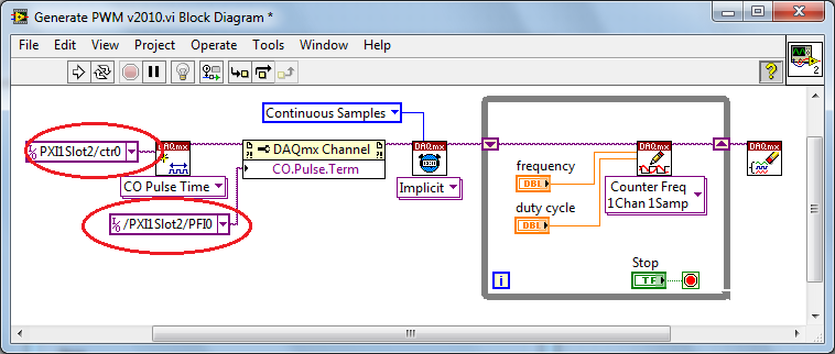
PWM - output meter (PFI4) USB-6211
I managed to control a motor based on PWM signal output via USB-6211 AO continuous. Now, I'm trying to use the Terminal counter instead.
Can't seem to make it work. NA not get a signal when link the PFI4 terminal to an oscilloscope.
I don't know wheather my coding is wrong or does not have my wiring (i.e. of USB-6211 for motor continuous). I need to use the terminal of meter that I used the analog output to a different measure.
Please advice. Attached encodings.
Thank you very much.
Front of conneting to DC motor, make sure first that the PWM is get generated correctly... use oscilloscope.
And have you changed the constant (physical terminals) for your device...?
Change to:
Dev1/ctr0 & Dev1/PFI4 and the scheme of connection must be:
-
Trigger start analogue does not work for the tasks of the analog output
Hello. I wonder - what someone has tested the trigger mode analog start for continuous output voltage-. example of VI under hardware input and output - analog output folder in the Labview.
My camera's SMU-6358, who has two lines APFI and supports analog trigger. Although it is very difficult to find information on the use of analog trigger for analog output of the tasks, what I've learned so far is to connect the interested analog trigger signal (such as an external noise) on both the AI channel which is used as a source of relaxation (ai0 in my case) and a two-channel (APFI0 in my case) APFI.
During the test the example above vi, any level of relaxation that I put (even with 0), the task of output did not work at all. No error message is returned either. Just for your information, I do physical tests, not only the software simulation, so no signal means no signal.
Any help is appreciated!
I have here is that the solutions to this issue, just want to say thank you to all who have helped me on this subject.
Use the analog analog trigger output tasks, make sure that the trigger signal (input HERE) is connected to APFI0. There is no need to connect the trigger even signal to ai0 if you do not want to save the trigger signal. However, if you do not want to save the trigger signal, connect the trigger signal to both ai0 and APFI0 with a signal splitter. In the latter case, the task of the AI shouldn't take the same trigger that the task of the ao. This means that you can start your registration with or without a trigger, while leaving the task of ao wait a trigger of some signal. This is useful in a situation that you only want to generate ao task to a certain trigger event, as when a signal reaches a certain level of sound pressure.
-
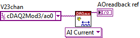
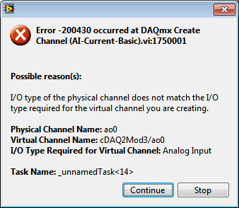
Read analog output channel value internally
According to this you can read the values of analog output of return without having to physically connect the wires.
By using the technique described in the example given (DAQmx_Read_Output_Internal_Channels.vi) I'm reading a current area of OCCUPANCY on my compactDAQ cDAQ-9174 with a module of analog output current OR-9265.
The output channel is created in MAX and my vi can write values to him without problems
But when I try to create an analog input channel to read the output, an error occurs.
What I am doing wrong?
This is not supported by my hardware?
Or is the example given in the above incorrect link?
The example is 10 years old. Maybe, it does not work in LV2013.
Hi Jocker,
The link was not attached to your message, but I guess that's it: http://digital.ni.com/public.nsf/allkb/CB86B3B174763C3E86256FFD007A2511 as there the example of vi you mention.
The error you are getting is due to the use of the channel for analog output and trying to configure the task as a task of entry. You must use _aoX_vs_aognd as the channel of the task rather than on the output channel. This compares to the ground for the analog output values.
The NI 9265 is not on the list of the C Series modules that have internal channels:
So I guess that the module is not able to compare its output to ground. He would appear in the dropdown of the channel names if available.
Pete
Applications Engineer OR
-
Hello all,.
Asking if any user can check that the DAQmx; Channel Properties node; Filter; Calculation of the average of windowing is supported by the NI USB-6211 OEM Board?
This feature is essential for the intended application and need to know before ordering.
Group thank you,
Chris
Hi Chris,
> By 'no it isn't' I assume you mean that it cannot be what I need. Make you that statement, even if you don't know whatever it is general or specific to the needs of my application
 )
)I wrote "No, it isn't" as an answer to your question. I should write, "no, the AI. AveragingWinSize property is not supported by the NI USB-6211 OEM Board. »
Brad
-
It is current on the analog module USB NI 9263 output voltage limit (+/-10 v)?
It is current on the analog module USB NI 9263 output voltage limit (+/-10 v)? I try to run a current controlled resistance, but cannot get the required current. The servovalved has a parallel internal resistance of 80 ohms and requires 20 my full operation. Ohm's law: (.02 A) * ((80*80) /(80+80) ohms = 4.5 v) Yet, the required voltage, do not move the servo. Outside the material error (continue this by other means), what could be the problem?
Have you checked the Manual?
Page 12 1 says my.
For servo, you really need some kind of amplifier. See if the manufacturer provides the electronic driver for it.
-
Sampling frequency for the output of an acquisition of data USB-6211 card?
Hello-
I use a CGI CMOS FireWire camera to read an interference figure, then using a transformed of Fourier transform spectral interferometery (FTSI) phase recovery simple algorithm to detect the relative phase between the successive shots. My camera has a linear 28 kHz scan rate, and I programmed my phase retrieval algorithm take ms ~0.7 (of a trigger of camera at the exit of the phase). I use the live signal to control a piezoelectric stack, by sending a voltage single sample to the analog output of a data USB-6211 acquisition card.
Send this output voltage increases the time of my loop 4 m, I would really like to achieve a 1 kHz or better sampling rate. Is the problem with my DAQ card or with the processor in my computer? The DAQ cards of NOR can support these speeds?
Thank you
-Mike Chini
Hey Mike,
With USB, your loop rate will be around or under 1 kHz, even on the best of the systems. USB has a higher latency and less determism PCI and PCIe. You can get rates AO one much better sample on a PCI card, potentially a PCI-6221. We have a few HAVE points of reference for targets of RT for PCI, / AO in a loop, you should be able to get similar performance in Windows, but if you do a lot other treatments may suffer from your local loop rates.
Hope this helps,
Andrew S
-
Simple examples of analog output USB-6343
I've tried passing by 'find' examples and does not know how to find what I want.
I'm doing a simple analog output on a USB-6343. Examples of waveforms say they work with the USB-6343, but I really don't want a waveform, just analog of output does not exceed 10 Hz speed of renewal. Some of the more simple examples show that they work with the pcie-6343 but do not list USB-6343.
I worked with USB-6009 in the past, but when I try to use an analog output task that uses 1 sample on request, I get the error "not buffered operations clocked by the hardware are not supported for device and channel type.» Set the size of greater than 0 buffer, do not set up the timing of the sample clock or the value Type of sample On Demand time"
I tried samples N, 100 samples to write to 10 Hz - the same error. Samples of continuous - same error. 1-sample - timed HW - same error.
There is a series of examples of I/O for the X series? Is it possible to search the device examples rather than go through all the examples and by checking the list of devices individually?
Is 'size of the buffer' the 'writing samples"in MAX?
After contacting the support I was provided with the names of the more simple examples for analog i/o:
Analog output-Gen power Update.vi
Analog Input-Acq & chart voltage-Int Clk.vi
They are found in the getting started screen of
Click 'Find examples' near the lower right corner
Filter the results to material by clicking on the menu drop down for the material in the lower left corner and selecting USB-6343 (only connected equipment will be displayed)
Don't forget to check the box "limit results to material" below.
In the center pane, double-click 'Material Input and Output'
Double-click DAQmx
Path for the analog input - double-click Acq & chart analog measures - double click on tension - tension-Int Clk.vi
Double click on analog generation - double click on Power - Gen Update.vi of analog channel output voltage
The examples are for the single data point. Samples and exit multiples are produced by putting the writing or reading VI inside a loop. The beginning and the clear functions should be out of the loop.
Additional information, I need technical support was how material-filter results and identification of more simple examples which were not obvious from the examples of names.
Maybe you are looking for
-
Sending Albums Photos from iPad to Mac
How can I transfer an ALBUM I created on my iPad to my iMac? I know that I can transfer individual pictures, but them that I would need to recreate the album still once, it seems. I have the OS X El Capitan and the latest photos on my Mac and iPad s
-
I need to change the note/endnote.
I write my RESUME, and I have a large number of appendages, that I have to put in the body of the text. I tried to do in the pages and the best option is to use an endnote, but I need to change the Exhibitor in order to appear ' doc 1 ' ' doc 2 '' '
-
Update problems - how to prevent an update available
title of the debtor: update problems On XP, I recently uninstalled .net because it was originally a slow race. The result is a much faster computer but update Downloader insists to send me, updated net what failure then to install. How can I stop sen
-
Now, I am aware of the modification of the properties of the file is simple in Windows 7 Explorer. Select a file, 'Properties', then tab "Details". Some are not editable, and that's understandable. Click on next to any area classified as year, Genr
-
Hallo, a die specialists, ICH habe an meinem PC somehow den your ausgeschaltet und also nicht wieder year Kann mir vielleicht bitte helfen someone out? am PC bin ich noch unbeholfen something. Also bitte, bitte mit Geduld imagine! MIT thank wurde und