Fast analog generation ramps simultaneously
With the acquisition of data-mx, trying two fast and simultaneous output analog ramps. I created the attached .vi and know that if I try just an exit ramp, my method works. However, when I add the second a ramp channel generates a ramp and when it's over the other ramp is released on the second channel. Can you find my error?
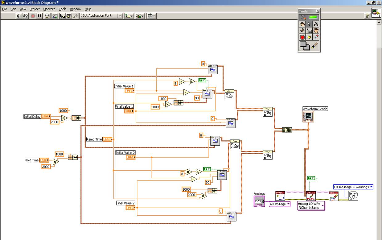
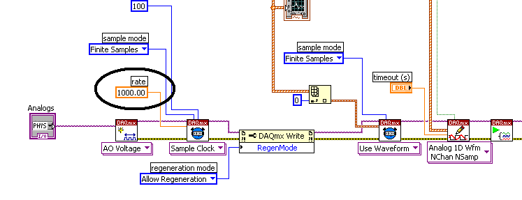
Try increasing the rate constant to something appropriate for your hardware (i.e. within the maximum sampling frequency for your hardware). You can try to 50000. You will also need to change the waveform generator sample speeds too (they are all set to 1000 Hz). Maybe make a control on front panel and replace all constants of 1000 with a wire to the control.
I hope this works!
Tags: NI Hardware
Similar Questions
-
Digital and analog generation and acquisition using USB-6251
Hi all
I have to actually synchronize a 6251, USB and USB 6366 Board. I have a vi, which is good that now I am able to use the 6366 as the master and as slave 6251, attached tie. The master generates a digital trigger for (generation synchronization) pulse and the acquisition of the signals on both cards, analog signal ramp and acquires signals. The slave acquires only a series of signals after outbreak.
I want to have the 6251 as master and as slave 6366. The vi attached the other way around as I mentioned above. When I try to use the 6251 as the master, I get an error asking me to specify the clock source (I did the material and some changes in the program as well, as export properly 6251 at 6366 clock).
Thank you
SANJU
Thanks for your reply jonathon,
But in your code below, I coudnt get the Outpput internal PCI-6251/ctrl0...
but I hardwaired the o/p (PFI 12) meter... .and generated a signal meter on this port, I used that as the clock...
Thank you
SANJU
-
discontinuity of analog generation
Hi, it was suggested that I post this question here rather than on the set of Labview where it was posted.
I work with an acquisition of data, OR USB - 6221 BNC and trying a continuous sine wave analog on output. Finally it will be output on an external device, but I am try it now and get a discontinuity in the received signal on the same device with analog input. I use the examples of programs Acq & chart voltage-Int Clk.vi & Cont Gen tension Wfm - Int Clk.vi and am display a waveform of 1 kHz at a sampling frequency of 200 kHz, well within the Board of Directors. and delivery of a complete cycle of the buffer. Using only one channel on the record, that I am seized at 192 kHz, I understand shouldn't be a problem because I don't share the A - D input with other channels (since it's my only job). The problem is visible when the amplitude is less than 80mV.
In response to questions about the other post, I took a shorter record to show the different cycles on the entry with the sporadic spikes. As can be seen in the photos, the cobs intervened crosses zero wave. I hope to exclude external interference, I unplugged the cable BNC output while generating and recorded and had a flatline (as would be expected), I also set the amplitude of output to 0V and again registered a flatline. Any help would be greatly appreciated
Thank you
Sam
Hi Sam,
The behavior you're seeing is likely to be a behaviour known and specified for the output of analog of this card. It looks like the dissipation of fees that accumulates in the DAC in normal operation. This behavior is specified under the heading 'Glitch energy' HERE in the specifications of the 6221 OR. As it is specified as 100mV, it makes sense you only see it during the generation of the small tensions, since the NFS is much less. One option here is to implement a low pass filter to try to get rid of this problem on the output of your 6221.
I also found another forum on the same issue HERE.
I hope it's useful.
Chris W
-
Analog generation using USB-6259 with C native
Hello
I've developed a sort of access library (with a unified interface for all types of tasks) for device 6259 and I don't know how to generate an analog voltage (other reports probably too) the way I want. I can generate finite or continuous signals, but only with the specified buffer samples (the signal is so very periodic). My intention is to use everyNSamplesEvent to change the contents of the buffer, so I can easily generate user-defined signals. I noticed the change in buffer is done when the task is stopped. But I don't want to stop the task to swap the contents of the buffer. How can I do this?
Hello
You develop this application using LabWindows CVI or Measurement Studio?
Can you please tell me what the DAQmx driver version are you using?You can see this example if you are using LabWindows CVI.
http://zone.NI.com/DevZone/CDA/EPD/p/ID/1733If I understand correctly you want a non regenerated output.
Please let me know your status.Kind regards.
-
go DC for analog generation with hardware trigger
Hi, I would do the following:
-Together a terminal to user defined voltage CC
-Switch to waveform base voltage generated when a hardware trigger is received
Is it possible to do this with a multifunction DAQ card? I have the impression that seitching of the DC to waveform generation can be done in software. This would lead to some downtime. How long will the dead time? The voltage will be stable over this time?
All comments welcome
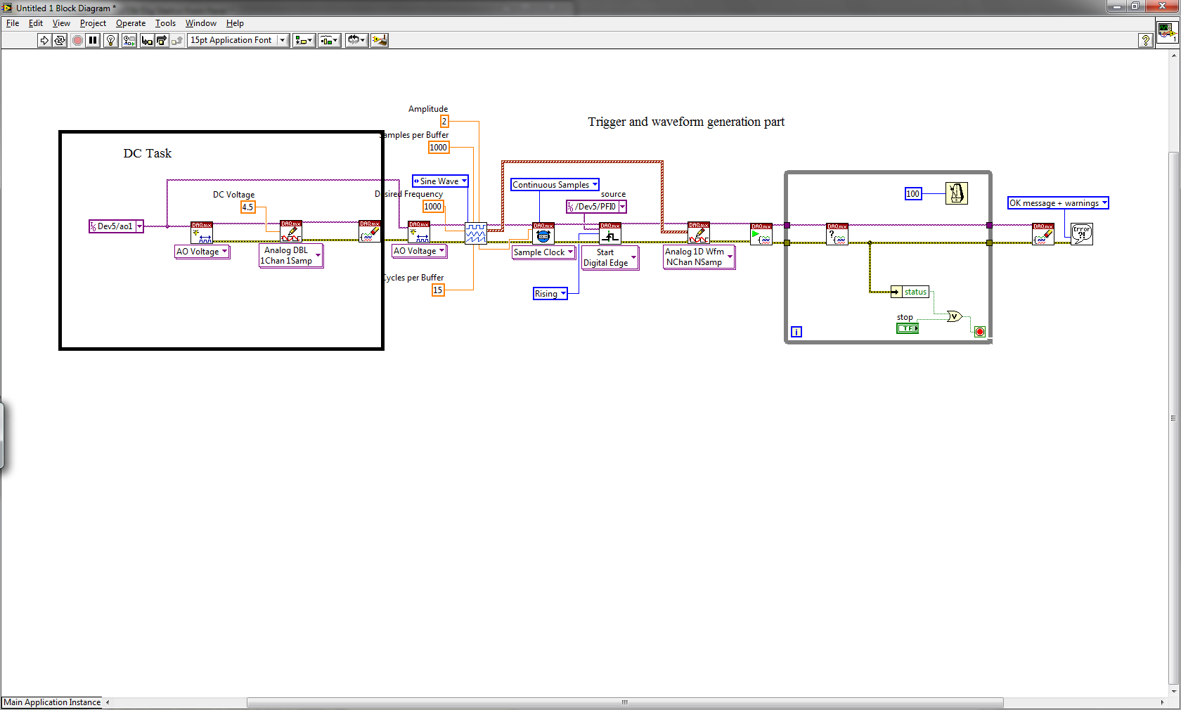
Hello Dixie,
See screenshot of the joint, this could be an option. First of all, you can do a DAQmx task that allows you to send a continuous tension, when you disable directly task the DC output will remain at the level you selected before. Then you create a task DAQmx will send a wave form and waiting for a trigger to do. The output will be at the DC level until there is a trigger so the waveform will be produced.
Casper has soon
-
Counter the acquisition and generation of simultaneous signals of Daqmx triggered
I am writing a vi that collects the data of a specific length (1000 points) when writing the data of the same length on another port on the same card (PCI-6052e). Collection and production are both triggered by a pulse of a counter on another Board (PCI-6711). I am able to trigger both successfully, but not at the same rates and not to the desired resolution. The generation of waves and the collection forms should be 8 msec in duration. I have attached the screws. Any ideas would be appreciated.
Thank you
Jordan
Eventually clocked continuous generation, but the displacement of the wave write vi DAQmx out of the loop (just before the beginning of vi), and this fixed the calendar.
-
How to write constantly to analog output and read from analog inputs
Hi all -
I had a question about writing continuously to analog output reading simultaneously an analog input.
It's my first time to post a message to the community, so please let me know if I made mistakes.
I use Labview 2011 with a NEITHER-DAQ USB 6215.
I'm looking to generate a waveform and write it continuously in an analog output. It is then connected to an entry on the acquisition of data, where I am trying to sample the analog signal. (I realize, there is a system of trivial, but I'm hoping to build on it once I have run).
The task of reading from the analog input works fine, as I tested it in several other cases. I have a problem writing to the analog output.
For this task, I tried to follow the "Gen Cont Wfm Clck Int' VI to generate the wave form and start the task. I then try to write to the output of the analog timed loop. However, it does not seem to transmit a signal and doesn't give me any errors.
I have attached the VI but also a screenshot.
Please let me know if anyone has any ideas. I would really appreciate the help!
Thank you
Peter Borgstrom
We will review your tasks one at a time. First of all, the task of generation/Analog output Waveform. Generate you a waveform (I'm unsure of your VI if it is a fixed waveform or not) and send it to a defined output function to produce a waveform continuously, using N-channel and samples of N (where you set not these previously). You should not put this inside has timed loop, as the DAQ hardware has its own clock - if you simply put it in a while loop (with a stop to break out of the loop), the loop will call the function for the first points of N, wait until all N have been taken out, then call it again to another N points (up to what you press Stop).
Now, suppose that you have the output connected to a load voltage (say a decent resistance). You can wire the input terminals of your A/D converter through the same load and set up a similar analog input loop, running in parallel (i.e. in its own independent of the OD loop, while loop). You pourriez start together (with, say, a merged error since the initialization code line loops HAVE and AO become lines of error in "loops of sampling" described above), but you might want to delay loop (a little) the AI so that the OD has a chance to set the voltage before the bed.
I hope this helps.
BS
-
Please help on sig analog gen 1.2 ms
Hi guys. I need your help on analog voltage generation for 1.2 milliseconds. I really don't know about generation/maninupulation waveforms. I tried to change the two examples that I have attached, but I was unsuccessful. I tried to change: input frequency for the generation of signals, however, I can't manage :/ I tried to access the references/examples/responses of the net, however, I can't find any useful stuff. Could someone edit one of this screw for me generate an analog voltage over a period, specified in milliseconds. Are there any good resources to learn the signal analog generation/manipulation you can suggest? I thank in advance.
-
Timed by analog material out with PXI-6733
Hello
I'm a little confused on the possibilities for the material of analog timing of release of a PXI-6733, using pulses of DIO to a separate device.
I want to generate an analog voltage on the signal for synchronization from another device.
Lets say I want to generate tensions: 0, 1.3, 8, 0 volt. Sometimes 1 US, 402 U.S., 1004 US, US 1503. (we = micro seconds). I DIO card that will generate TTL pulses in these moments there and let's say I have the latter on a trigger PXI, PFI line line or enter the map of 6733.
How to configure DAQmx with labview to perform this task?
Thank you
Paul.
Hi Paul,.
There are many ways we could do this. The first thing that comes to mind is to sample AO clock battery LIFE of your device. All you have to do is do an array of doubles with the values that you want to scroll through and then then whenever you get a clock pulse we will update the output. You can see examples in LabVIEW by going to help > find examples. "" "The NOR example Finder will appear, and you can find many useful programs in input and output material" DAQmx "analog generation ' record of tension. To achieve my method, I opened the Gen Cont tension Wfm - Ext Clk.vi example and modified the code as indicated. I have included the code here for your reference. In my code, I plug my external clock in the clock via PFI0 source on my card. Now, whenever I get a pulse I will update the output voltage of 1 to-2 to 3-4, 1-2, etc., ad infinum.
-
Simple examples of analog output USB-6343
I've tried passing by 'find' examples and does not know how to find what I want.
I'm doing a simple analog output on a USB-6343. Examples of waveforms say they work with the USB-6343, but I really don't want a waveform, just analog of output does not exceed 10 Hz speed of renewal. Some of the more simple examples show that they work with the pcie-6343 but do not list USB-6343.
I worked with USB-6009 in the past, but when I try to use an analog output task that uses 1 sample on request, I get the error "not buffered operations clocked by the hardware are not supported for device and channel type.» Set the size of greater than 0 buffer, do not set up the timing of the sample clock or the value Type of sample On Demand time"
I tried samples N, 100 samples to write to 10 Hz - the same error. Samples of continuous - same error. 1-sample - timed HW - same error.
There is a series of examples of I/O for the X series? Is it possible to search the device examples rather than go through all the examples and by checking the list of devices individually?
Is 'size of the buffer' the 'writing samples"in MAX?
After contacting the support I was provided with the names of the more simple examples for analog i/o:
Analog output-Gen power Update.vi
Analog Input-Acq & chart voltage-Int Clk.vi
They are found in the getting started screen of
Click 'Find examples' near the lower right corner
Filter the results to material by clicking on the menu drop down for the material in the lower left corner and selecting USB-6343 (only connected equipment will be displayed)
Don't forget to check the box "limit results to material" below.
In the center pane, double-click 'Material Input and Output'
Double-click DAQmx
Path for the analog input - double-click Acq & chart analog measures - double click on tension - tension-Int Clk.vi
Double click on analog generation - double click on Power - Gen Update.vi of analog channel output voltage
The examples are for the single data point. Samples and exit multiples are produced by putting the writing or reading VI inside a loop. The beginning and the clear functions should be out of the loop.
Additional information, I need technical support was how material-filter results and identification of more simple examples which were not obvious from the examples of names.
-
Simultaneous multi-channel Imaging NI PCI-1422 or 1424?
We have an IMAQ 1408. We want to make simultaneous multi-channel imagery. However, 1408 has only 1 A/D converter, it cannot acquire multiple channels simultaneously. We are looking for possible upgrade.
The NI PCI-1422 or 1424 seem to upgrade products of 1408. Can someone tell us if they can do simultaneous multi-channel Imaging?
Sorry if this isn't the right forum for me to post this question. But I called the customer service OR. The guy doesn't really know acquisition cards. I think that there are more experts here.
If you have analog signals, it is a little more difficult. NEITHER ensures more hardware to read signals from analog cameras. I don't remember all of their equipment, be capable of more of an analog input signal simultaneously. They always alternate between the signals, a reading at the same time frame.
Your best bet would be to get an analogue to digital converter which converts the formats I've mentioned. You must make sure it is compatible (uncompressed, industry standard, etc.).
Bruce
-
Output of different analog signals through 4 outputs
Hi all
Exit 4 different analog signals from the PCI 6711 map: I need help. I intend to use the waveform function from the palette of analog generation vi. My goal is to be able to enter the 4 necessary functions, it sampling information and then leaving four available analogue outputs available to the Board of Directors. I saw the code example for the output on multiple lines, but it doesn't seem like he is able to create unique waveforms through the exits, they are all the same waveform. I've attached what I thought work, but I can not get my number of rows in the data to match my number of rows in the task.
Specifically, choose instance polymorphic Analog-> multiple channels-> multiple samples-> 1 D wave.
Your current instance you chose is for just a single line.
-
Is there a way to output simultaneously 2 waveforms on both channels (without interruption) of the same map?
I have a PXI6723. Can I output a 1 khz/3 volts on a0 and a1 waveform at the same time? I tried 2 different screws and I get an error from the task.
Thank you
Clint
Hello
Yes, you can generate different signals simultaneously on different channels. Did you do a forum search? When I searched 'many analog outputs', I had something like 160 hits.
In addition, given your short description of what you have tried, the error you receive is 50103. Search for '50103' why you get this error.
So there is a lot of information on the forums already on your question. Rather than reinvent the wheel, I will ask you at the first glance the information that is already there.
You should also look at the examples provided with LabVIEW. Under 'Help', go to 'example Finder... '. Material input and output... DAQmx... Analog generation"for a code that will point you in the right direction.
Hope that helps!

-
DAQmxErrChk gives problem (the specified resource is reserved)
Hello
I'm new to programming. I have a four channel USB DAQ. I use CVI to program the channels. One of the channels gives a simple output of a voltage signal while the other generates a square wave. I used the example programs for my code. I use the Volt update for the first string and the Cont Gen Volt Wfm - Int Clk example for the second case. When I run the program it compiles without error and runs. But when I start the generation of any type of wave for the second string and try to change the output voltage for the first channel, the program gives an error and stops at
DAQmxErrChk (DAQmxStartTask (taskHandle));
in the example of update of volt.
The strange thing is that when I'm not generating any output for the second channel it gives no error when I change the voltage to the first string.
Please please tell me what is the problem
The error that is displayed indicates that
The specified resource is reserved. The operation could not be performed as indicated.
Name of the task: task _unnamed<3>
Ststus Code:-50103
lahorimunda,
Please post on the Forums of NOR. If I understand correctly you are two different programs to run different channels? If this is the case you run through what we call that a reserved resource error is because you are allowed to have only one task of analog input running simultaneously. You will need to put all the channels within the same task, this will prevent you from running through the reserved resource error. I hope this helps.
-
Hello
I'm new to Labview and I tried to make this program work. The block diagram is attached. I use a NI - DAQ USB 6211 with DAQmx base on a linux machine. When the program runs normally, it does not produce anything, but in peak mode, it works as expected. I use a digital oscilloscope for test output.
Thank you very much
Enter the finder of the example and go to:
Material input and output > Daqmx > Analog generation > voltage
and look for updates of Gen Mult Volt-sw timed.vi
It is an example of what you're trying to do and have to clean up some things for you.
Maybe you are looking for
-
Recently closed tabs / windows recently closed won't be remembered?
Hi all FireFox is not saving my recently the firm or recently closed tabs Windows. I can open a tab, close immediately after going to a Web site, and the options for both under 'History' are always blank and gray. I have not installed or updated plug
-
Everytime I open the Mail (I have Yosemite) it closes unexpectedly, I ve tried everything, I deleted my email accounts (in System Preferences), files I ve replaced MailData folder and nothing has worked. Help, please!
-
Requirements:Mac OS X 10.6 - check - 10.6.8Macintosh computer with an Intel x 86 - check - 2.66 GHz Intel Core 2 Duo processor512 MB RAM - check - 2 GB200 MB hard disk space - check - 130,81 GB free Is there some sort of hidden requirement that I don
-
Created a log partition which is invisible and taking up valuable space. (El Capitan).
I've created a normal 175 GB partition through redesigned disk utility. It has been chugging along so I left it to itself, and when I came back my cell phone has been turned off. I restarted to find that my main HARD drive, which has a capacity of 50
-
Individually control the digital ports
Hello I'm getting a weird behavior when I run the VI attached on my computer out of ports digital test/control individually. I have not tested on real hardware because it is not available at this time. When the code is executed, the output pins are b