FPGA Virtex - 5 LX cRIO chassis
I noticed that the new chassis 8-slot cRIO is available in three different types:
Virtex-5 LX30 FPGA
Virtex-5 LX50 FPGA
Virtex-5 LX85 FPGA
What does the bolded numbers really mean? -Mike
It is the size of the FPGA:
FPGA Virtex - 5 LX30 - 19,200 flip flops
FPGA Virtex-5 LX50 - 28,800 FFs
Virtex-5 LX FPGASFFs 85 - 51.840
More info here-> http://zone.ni.com/devzone/cda/tut/p/id/6983
Christian
Tags: NI Software
Similar Questions
-
Missing items from NI 9214 FPGA of e/s (cRIO-9030 / combo NI 9144)
I have a new cRIO-9030 and the expansion chassis NI 9144 EtherCAT I configured and added to a project existing LabVIEW that contains a cRIO-9012. When I researched targets and devices, modules have been correctly detected (NI 9237, NI 9263 and NI 9265 on the cRIO-9030 and 9214 NI and NI 9477 on the NI 9144 chassis); However, the I/O items listed for the show of the NI 9214 module only 16 channels thermocouple (TC0 by TC15). Four additional channels do not appear (track and CJC0 through CJC2), although they did when the module has been previously configured for the cRIO-9012. It is a known / compatibility problem with the NI 9144? or y at - it a configuration option, I'm missing? The terminal block must be set up on the module for these I/O elements appear?
I think I have solved the problem. If I first add a FPGA target under the appliance NOR 9144, and then add the NI 9214 module under that, then additional channels appear. I guess that means that these elements of I/O are available when you use the NI 9144 FPGA mode?
Sean
-
Compilation of LabVIEW FPGA on crash RT cRIO 9082
Hello
I developed a project of NI VeriStand FPGA (see Project.png) for a target of 9082RT cRIO (which contains 2 cRIO: 9205 & 9264).
I have develop a piece of software code to run it on the chassis of RT cRIO 9082 because I never used this kind of front frame.
The problem appears when I tried to compile the FPGA.
Start the compilation, I see a pop-up (see Msg.bmp) and failed to compile (cf.). Details.bmp).
With the following error, I'm sure that the failure is not because of my code.
Can you help me?
I found the problem that comes from the installation of 2012 more develop.
When the FPGA module and 13.4 Xilinx tools is installed, the DLL 'LIBBz2.dll' (of the NIFPGA\...\Common\nt\Xilinx record 13.4 "is not copied in the following"C:\Windows\system32"folder.
After I manually copied this dll to the "system32" folder, I restart labview and the compilation was successful.
A. Kaszubiak
-
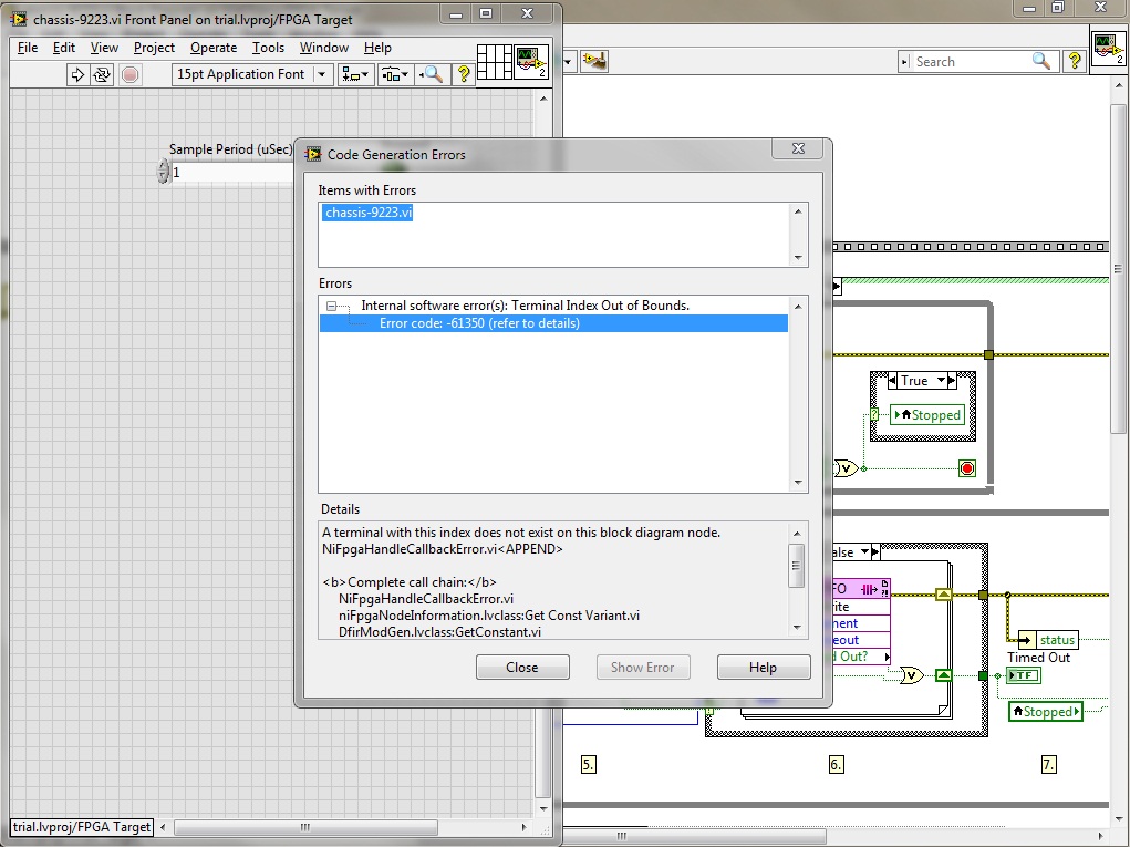
I get the error (in a popup window) when my VI FPGA code in chassis 9118 OR NI 9223 module compiled help. This error occurs when compiling the process (generating intermediate files, scene 7 of 7). How to solve this error?
Thank you
additional information:
Original error message:
-------------------------Errors:
Software (s) internal error: Terminal Index out of Bounds.
:-61350 error code
Details:
A terminal with this index does not exist on this block diagram node.
NiFpgaHandleCallbackError.vi«"" "String of full appeal:»»"»
NiFpgaHandleCallbackError.vi
niFpgaNodeInformation.lvclass:Get Const Variant.vi
DfirModGen.lvclass:GetConstant.vi
niLvFpgaMungerBrainwashIONodeCommon_Dfir.vi
niLvFpgaMungerBrainwashSingleIOGrowableMethod_DFIR.vi
nirviEIOMethodImplementation_SpecifyDFIR.vi
nirviEIOMethodImplementation_SpecifyDFIR.vi.ProxyCallerHi tesa,.
This is a bug that has been fixed in LabVIEW 2012 SP1. The number of CAR created for this bug is 332811 and as you can see in this link, it is already in the list of bug fixes.
Carmen C.
-
Data transfer from FPGA to RT in cRio
What is the best method to transfer a set of data in an fpga to a target of RT (using a sbrio).
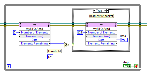
I have the FPGA generating fixed size datapackets (essentially a group of data), it generates these packets of a fixed size (128octets/package) sent My FPGA asynchronously to the RT code. The packest are generated at a rate of 0-1000 per second. In traditional labview, it would be a simple architecture of producer consumer with the cluster of queue type. I have a few ideas for FPGA, but want to use the recommended architecture.
Resources or ideas are welcome.
Yes, you will need to send the items one by one to the host through the FIFO. You can configure the type of data FIFO to be long until 64-bit (and half of bits-pack to your package in this data type). Or, you can keep the long FIFO data type of 1 byte and send 128 elements by package. In this case, you could do something like that on the host computer:
This would avoid host to pull elements of the FIFO, until the whole package is received.
-
Reading of mV current transformer connected to NI 9206 by cRio chassis
I'm reading a current transformer mV two-wire (+/-) with output between 0.0 - 0.4V. I have connected to AI0 channel (+) pos and (-) neg to the AI8 channel. Channel AI0 is set to DIFF, +/-1V. The pos (+) and (-) neg are also connected each their own 47Kohm resistance that are both connected to COM. Using a multimeter Fluke 189 I get a read out of the constant the +/-90mV son. 9206, however, returns a float value between +/-150 mV. Any ideas of what I'm doing wrong so I can get the 9206 to read in the same way as the Fluke? Any help would be greatly appreciated.
-
Crash when creating a new project FPGA cRIO
When I want to create a new project with the wizard FPGA cRIO, Labview freezes and blocks ("development system Labview 8.6 had ceased to function".) The wizard detects my cRIO-9073 integrated controller, but when he tries to discover the CompactRIO chassis, the program hangs and stops automatically.

In MAX, there is no problem discovering the FPGA chip in the cRIO-chassis (RIO0)...

I tried to use the new FPGA Project Wizard in Labview 8.5. While searching for the cRIO chassis, the program does not freeze, but he says the cRIO-chassis cannot be found...

When I want to manually select the chassis, I can only choose for the cRIO-9072 and cRIO-9074. There is no cRIO-9073-icon...?

What I am doing wrong, or is this a bug?
Kind regards
Kenneth
-
How to read the status of User1 DIP-switch with a cRIO FPGA chassis?
How to read the State of the DIP switches on a FPGA cRio chassis?
I work with a cRIO 9022... My idea is to put the system in "service" mode with USER1 switch to IT and communicate with the FPGA via the FPGA - GUI (VI) on the host computer instead via the RT module that is used in normal conditions.
Any ideas? Unfortunately, I don't have an unused channel on the left... .and (as I know) cannot use the interface RS232 of FPGA.
Many thanks in advance,
Luke
Hi, this is the correct information. You cannot read the FPGA of DIP-switch status. The only thing you could do is to use the function of Reading Switch.vi located under the range of functions-> real-> utilities RT time
It's how you probably know side host RT and not the FPGA.
Cordially Virginia
-
CAN the c series modules and drivers XNET and Ethernet expansion chassis cRIO compatibility issues
Hello
I encountered a problem with my current setup which was not picked up by the tool advise cRIO or by the engineer of applications OR that we used to check our configuration before starting the project. It turns out that the NI 9853 CAN modules require a XNET driver that is not compatible with the NI 9149 expansion chassis.
We currently have a system with a cRIO NI 9068 with general IO and some CAN controller and CAN open modules in a carrycot and an Ethernet NI9149 with more general IO expansion chassis and more CAN and CAN open an another pod remote modules and all of this should work under water, so I can not move the modules of the expansion chassis to the chassis controller without a lot of overhaul of the system and equip and a team of angry engineers and technicians.
I have developed the FPGA code for the 9068 OR and have CAN and CAN open networks works with happiness. Then I tried to copy the same FPGA code on the expansion chassis and it compiles, but when I try to launch it I get the error-63184 code. After long calls OR support, and tries to install the missing drivers on the expansion chassis, we discovered that XNET is not compatible with this chassis.
Can anyone suggest the best course of action? Is there an expansion chassis Ethernet that will support XNET? I have here no information online about this compatibility issue that I can't find?
I'll be communication with DIRECTLY, but from previous experience of the "odd" questions, I know the community often hold the key. Any suggestions gratefully received.
Thank you, Ed
It's official. CAN open modules are not compatible with the expansion chassis. I have them moved to RIO and will get the upgraded pods.
Thank you
Ed
-
Mode of scanning/FPGA for a CRIO by Veristand
Hello!
I have a small error using my CRIO 9081 use with CAN communication, here's what I did:
1. I use the CRIO with scan mode and customized it "Scan engine" and Ethercat for show my analog modules under VeriStand, it's ok
2. I use the CRIO with FPGA Scan interface (together under Labview) to detect my modules CAN, also ok
3 - then I wanted to see the CAN and analog modules, so I use this page:
http://digital.NI.com/public.nsf/allkb/0DB7FEF37C26AF85862575C400531690
And here's my problem:
with this method I am able to see the two modules with the custom device 'analytical engine and ethercat", which is really nice, BUT, impossible project VeriStand, the error message asking me to turn the chassis using FPGA, but then I lost the analog module...
So is it possible to run a project Veristand using both Scan and FPGA interface mode?
Thank you very much

Hi Vincent,.
When you tried to implement, you use the procedure described in the following document in the section use of Scan Engine and EtherCAT with NI 986 x custom device modules XNET ?
From what I remember, because you use a cRIO-9081, you will need to compile an empty bitfile for your target and place the controller in Mode FPGA hybrid mode on your chassis.
Could you post a screenshot of the error of deployment, you see?
-
Is it possible to have a multiple FPGA cRIO system?
I'm curios if it is possible to have a single cRIO chassis that can be extended with additional FPGA for calculations. Which means, I have more I/O but I algorithms take too much space and need a secondary FPGA to perform parallel processing. Data would be generated in the first FPGA and communicated to the second FPGA where additional processing takes place and then a command/response is returned to the first FPGA which will then be sent through the IO.
I saw something "similar" to that in PXI: http://zone.ni.com/reference/en-XX/help/372831C-01/p2pstreamhelp/p2plv_topo_pipelinefpga/
Although this solution depends directly on the SMU bus there the general feeling for what I want. However, I need this in cRIO. Is there a solution that I missed in my navigation of NI.COM?
It would be OK if the solution uses one of the slots on frame cRIO.
A cRIO chassis only has 1 FPGA on it. You may be able to get an expansion chassis and pass data to it in order to do the treatment. For what you're talking about, you probably want to add a few DIO so that you can directly communicate with the expansion instead of going through the RT chassis and the analytical engine.
You can also get a cRIO with largest FPGA and/or your representative local to la OR the chance to see if you can get some time with a systems engineer OR that can help you optimize your code to fit on a single FPGA.
-
Chassis FPGA deployment problem
Hello!
I use cRIO 9024 with a voice coil actuator control modules.
The problem I have is that when I run the FPGA code, he said "the chassis is in programming mode Interface to Scan. In order to run the FPGA screws, you must go to the property page of the chassis, select the FPGA programming mode and deploy settings. »
So I checked the property, but it has been defined as "FPGA programming Mode. Also when I'm trying to deploy the chassis, I have error message "LabVIEW: (Hex 0x80DF0010) current deployment operation has a missing dependency."
Since I'm not the one who wrote the code, I have no idea what causes this problem. This code is used for the different game with the same model of cRIO but different modules. I've already replaced modules that I use with those that are necessary for this code.
Anyone know what is happening here, please?
Thanks in advance to 1 million.
Geehoon
-
using slots chassis for general use cRIO
Hello
I have cRIO-9004 and cRIO-9103 Chassis, labview 2011...
AFAIK, the cRIO chassis controls its slots if it present any module or not... If someone detect read EEPROM and so on...
But how can I control the slots on the frame cRIO for my own general use without any module...
When I create projects, it shows me just like I/O chassis
* chassis temperature
* LED FPGA
* Scan clock
* Sleep
* the system reset
I couldn't write anything of chassis slots and see to the oscilloscope screen, (for example: using a digital or analog output)...
Didier...
Try to follow the steps, you will create a new module. As in this example, but skip the part of the circuit.
-
Many FPGA target as a controller cRIO
Hello!
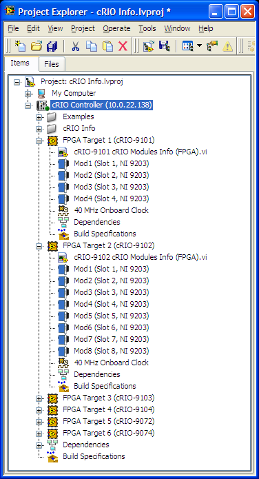
I was reading the cRIO System Configuration Information (CRY) Encarta article (http://www.ni.com/example/51852/en/) and here the Figure 9 shows a cRIO controller with multiple FPGA targets. How can this be accomplished?
In my case, when I tried to add a 2nd FPGA target, under my cRIO-9076, I get a message that can only be associated with the controller.
Any ideas?
Support of claims library CRY to LabVIEW 8.5.1, which leads me to believe this screenshot was taken in this version. The RIO Scan Interface/FPGA Scan Engine (IRS) have been introduced in LabVIEW 8.6 and NOR-RIO 3.0.x. To include this support, introduced the notion of a frame in the LV (notice there is no chassis under the Comptroller in the screenshot). To facilitate the RSI and the analytical engine and provides a more accurate representation of what is actually available in a system, you can only add a frame by controller. This allows the IHR charge the correct controllers for deployment.
BT 8.5.1, you can add multiple targets to an integrated system controller/FPGA (as the cRIO-9072) even if there is no way that could happen in real life, so it's not really desirable. You can always do is to add multiple FPGA targets (even chassis cRIO) in respect of the purpose of the workstation in your project. Still allowing you to communicate with the target FPGA, but no screws will run on your PC system, not the cRIO controller.
-
Hi all
We have NI 9421 digital input and digital output NI 9472 Modules. We can run these modules into a VI under the 9073 cRIO chassis. While we have added the FPGA target under the same chassis, we cannot use the modules. We also install the scan engine.
How can we use FPGAS and i/o Modules at the same time?
Once you add a target FPGA in CompactRIO chassis, when you deploy the code, the cRIO is configured for the FPGA mode, which requires a bitfile compiled to connect with the C Series modules. Remove the target FPGA or changing the mode of chassis in the project and by redeploying must reconfigure the cRIO for scan Mode, which allows you to use the IO module directly from the RT VI.
For more information, see this post.
Maybe you are looking for
-
Manual configuration of the proxy don't glue - don't stay - pass when the tabs.
Suddenly, in the 27 new FF, when I manually set a proxy, it turns off (goes back to the 'No proxy') when I tabs or open a new tab. He used to stay up until I turned it off. I want him to stay through all the tabs up to what I turn it off, as he used
-
DAQmx shown writing as broken, carefully read
I'm trying to do a test day, it was originally at 8.6 and I took it in 11, also I can't work on it on the system where it is running. (it is heavily used) I have exported and imported settings MAX from the old system to my system the VI indicates the
-
My acer aspire AS5742 guard sudenly turned off loptop
I apologize because im new here, I could be on the wrong thread or whatever it is. So my acer loptop AS5742 I used it for 5 years now and I don't think that his old man he needs of recycled. The problem, it happened a few days that I have installed a
-
WRT610N and compatible usb drives
Hello Has someone managed to get a stable connection to the external hard drive USB on the WRT610N? I would use a hard drive enclosure that turns down the drive with a sleep mode for reasons of noise and energy. With the latest firmware (1.00.02 B10)
-
lights flashing c5380, no local control, no connection.
My Photosmart C5380 all-in-one won't start. "It flashes (1) / Off (2) red eye removal ', (3)" Print Photos"and (4) MORE ZOOM lamps at the same time. I tried powering down of procedures to reset several times. There first unplug & off for several days