Integration of VHDL code?
Hello world
We have developed material transmitter and receiver OFDM and SOQPSK-TG, using the rest of the FPGA design. Previously, we were using LabVIEW FPGA.
My question is, how do import you pre-written VHDL code to be compiled later in design? I can't find a way to do it, which wasn't possible with the LabVIEW FPGA software. With what type of VI FPGA target would you start?
Thank you!
-Brian
In fact, even if it is not well supported, it's also not impossible...
The general process is to create an IP-XACT file and use it. There should be an example of what this looks like in x 579 or USRP project examples.
Tags: NI Products
Similar Questions
-
Integration very old code & amp; a new code
Site and existing domain name is
www.dial4delivery.NET
New site is
www.fourdelivery.com
By clicking on both of these domain names, you should see a html file additional (I made a blue solid rectangle) on the left side of the page when viewing through the domain name dial4delivery.net.
What should I do to remove it?
You use sets of frames on this page. You don't need them.
http://dial4delivery.NET/navigate.htm = the left blue column
http://www.fourdelivery.com/index3.html = the main content
Also, look what happens when you aggressively increase the text size in the browser
index3.html page. Divisions of absolute positioning (aka layers) are
ruin your site.Read this:
http://apptools.com/examples/pagelayout101.phpNancy O.
ALT-Web Design & Publishing
www.Alt-Web.com -
Using of FPGA VHDL IP and analog output
I use a system with Labview 2014 PXI. I've got Labview FPGA to program and run the card PXI-7854R.
I have the VHDL Code I want to use to control an analog output of the card. I use the IP integration node for this now but I also tried it making the process CLIP and still have not been successful. The problem that arises is that the IP integration node must be in a timed loop, while the analog output indicates that it cannot be put in a timed loop. Is there a way to provide an output of VHDL analog outputs of the card?
I tried to embed a loop timed within a while loop, but it still does not work.
I can't download the VI due to the policy of the company, but suppose I'm generating a sine wave in my VHDL code which must lead to the analog output of the card (the actual wave is company owner information but it is generated by a glance to the top of the table as a sine wave VHDL would be).
In an attempt to work the problem I retried import CLIP of the HDL code in a new project in Labview and VI. I'm still not sure about why it did not work with each other when I tried it.
For anyone who seeks to solve this problem:
I basically used this tutorial for the process CLIP: http://www.ni.com/tutorial/7444/en/
It also explains the differences between the CLAMP and the IP integration node.
-
Hello
I have to import the VHDL code in Labview. I would like to know what the best solution what CLIP, integration IP node or node on HDL from the previous version of Labview if it is possible to use it.
Thank you
Hello
I think that these documents will help you to choose from, depending on your needs:
Difference between nodes CLIP and HDL
CLIP and the differences of node IP integration
Kind regards
-
Integration of IP node evil in LabVIEW FPGA
Hi all
I am having trouble with the integration of LabVIEW FPGA IP option and was hoping someone could shed some light here.
I use a simple VHDL code for a bit, 2: 1 MUX in order to familiarize themselves with the integration of IP for the LabVIEW FPGA.
In the IP properties of the context node, the syntax checking integration says:
ERROR: HDLParsers:813 - "C:/NIFPGA/iptemp/ipin482231194540D2B0CC68A8AF0F43AAED/TwoToOneOneBitMux.vhd", line 15. Enumerated value U is absent from the selection.
but I'm still able to compile. Once the node is made and connected, I get the arrow to run the VI but when I do, I get a build errors in Code Pop up that says:
The selected object is only supported inside the single-cycle Timed loop.
Place a single cycle timed loop around the object.
The selected object in question is my IP integration node.
I add a loop timed to the node, but even if I am able to run the VI, it nothing happens. the output does not illuminate regardless of the configuration.
I would say that I tried everything, but I can't imagine would be the problem might be at this point given that everything compiles and the code is so simple.
I have attached the VI both VHDL code. Please let me know if any problems occur following different boards of the FPGA.
Would be really grateful for the help,
Yusif Nurizade
Hey, Yusif,.
Looks that you enter in the loop timed Cycle and never, leave while the indicator of Output never actually is updated. Try a real constant of wiring to the break of the SCTL condition. Otherwise, you could spend all controls/indicators inside the SCTL and get rid of the outside while loop. You can race in the calendar of meeting bad in larger designs without pipeling or by optimizing the code if you take this approach, however.
-
Hello
When compiling a fairly basic FPGA VI, I get the following error:
61332 error occurred in niFpgaCompileWorker_ProcessStatusPipe.vi:1<><>
Possible reasons:
LabVIEW FPGA: An unexpected error occurred with the build tools. You try to compile the FPGA VI again could solve the problem.
The length of a line in "NiFpgaAG_0000002e_WhileLoop.vhd" is too long for xilinx 10.1. Length: 32845 Max length: 4150
Departure time: 17:22:06
End time: 17:22:12
Total time: 00:00:06Apparently, the vhdl code generator OR forgot to add some CR + LF in the intermediate files. How to work around this bug?
Kind regards
Lukas
Hi Lukas.
When LabVIEW compiles a VI, the VI is converted into virtual hard disk to be compiled into a file bit by Xilinx. As you have already understood, this error indicates that a line of code vhd had a length of 32 845 characters, which exceeds the maximum length of 4150 characters for the Xilinx 10.1.
Although 32 845 characters is very long, it is possible that this is due to the codification of LabVIEW rather than a bug. Some common causes of this problem include large enums, a matrix, or clusters in the code. Please check in your code. If you have no luck, please attach a screenshot of the code. I hope this helps!
Kind regards
Dayna P.
Technical sales engineer
National Instruments
-
Hello
One thing bothers me and I would like clarification.
During the "run Labview transforms its graphic code vhdl then vhdl en Bitstream .
LabVIEW being synthesized, can get it back the vhdl code and the compiler on another software like model sim, simplorer... etc.
If so, I think that is not forced d ' use a card nor pour Configurator FPGA.
Thank you for being explicit, so that others can be answers

Hello
The LabVIEW FPGA compilation scheme is owner and therefore closed.
In other words, there is no way to recover the intermediate VHDL files.
This is illegal, and ownership of OR
Nice day
Well cordially
-
CDC code model mapping in OWB 11 g R2
I'll implement the feature of CDC in OWB 11 GR 2. I'm working on the example in the OWB, guide. Everything is going well until I tried to create the executive unit for the mapping of model code. When I created view Executive, I'm supposed to select the model code JCT_ORACLE_SIMPLE in the drop-down list, but I could not find this model code in the list, it shows that integration and load Code patterns (JCT change data capture template draw!).
Help, please! I follow the steps exactly and everything was fine.
Thank you.Hello
in the context menu of cdc of your db module, you must also call "extend the window" and "locking Subscriber.
Then you should be able to read the data of the JV$ _-view.Kind regards
Carsten. -
Server Side includes in render mode Code
I use Dreamweaver for many years now, and our sites extensively use SSIs. Normally in code view, the just IMS appears as an HTML element include. But since the Dreamweaver 8, some of the SSIs are appearing as the content of the SSI mode code. This is an option that should be off somewhere. I don't want information of SSI is integrated in the code every time, I download page.
Thank you
MarkDW--> invisible elements preferences
It is at the bottom of the list in most versions> Is an option that must be
> off somewhere. -
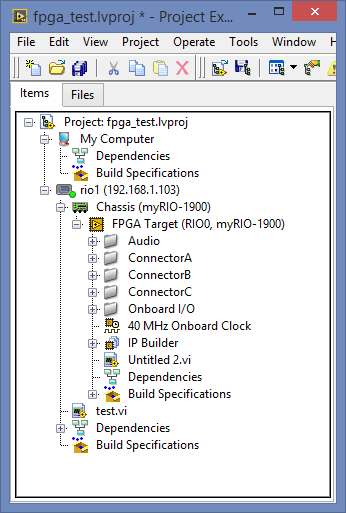
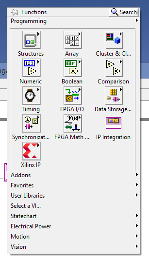
Cannot find the HDL Interface node
I have MyRio and LabView 2014 with all modules installed and updated to date.
Xilinx 2014 is also installed and I can compile for FPGA.
However, in the block diagram I find interface HDL node for the import of VHDL code. As see you in the second screenshot.
How can I solve this problem?
There are no node integration IP in 2014 of LabView. Use instead the HDL Interface Node.
Yes I used the HDL Interface Node and it has worked very well.
-
How can I import Verilog code in LabVIEW FPGA? I understand how to import the VHDL code by using a CLIP or IP integration node, and I wonder if there is a possible method to import the Verilog code.
Thanks in advance!
You can import verilog in labview by generating a netlist from verilog giving you a UCS or edif file depending on whether you use ISE or Vivado respectively.
From there, you can try directly imported the netlist labview using a node IP integration or you can wrap it in VHDL and create a CLIP of it. I recommend the latest, but we invite you to try to be.
To generate the netlist you will need your own copy of the OCDS Xilinx. Xilinx provides documentation on how to generate maps using their tools.
-
question of myRIO sequential clip
Hello
I realized a CLIP, and I wonder how to implement it.
The vhdl code is used to send data on the falling clock edge and read in the data on the falling clock edge.
Send and receive takes about 30 clockcycles. The code is based on a state machine and starts to send once an enable signal is given. Transmit/receive all the bits, he returned to idle.
I read that the CLIP would go even if it is not placed in a loop. However, when I do a test vi that has an LED connected to a few outings, it seems that it is only launched once? Or is it actually running, but the LED is not updated? I don't know how to implement is.
Use this CLIP in a time loop of single cycle? He would still use the fronts and the clock edge? And it would cause problems because it is sequential and combinational not?
Thank you for your help.
kind regards,
Bastiaan
Hi Bastiaan,
You read a 40 MHz signal each 25ns. So that means that you will read the same value of the signal in each iteration you will always show the same value and you will have a consistent performance. In order to get a signal to the correct frequency on you must perform the loop with a frequency of at least double the signal. You can create a clock FPGA derived in the way that this article describes. Use a clock of 80 MHz for the SCTL.
http://zone.NI.com/reference/en-XX/help/371599H-01/lvfpgahelp/creating_fpga_derived_clk/
Let me know if it helps.
Kind regards
Tom
-
I'm new to LabView FPGA and am currently trying to compile my VI on the target FPGA (an NI PXI-7842R).
The initial phase (what seems like Labview generating the VHDL code) appears to run successfully.
The next step (which seems to be the actual compilation on the FPGA) runs for a short time, and then reports an error at the end of the phase of PlanAhead.
The error message says:
LabVIEW FPGA: An internal software error in the worker of compilation occurred.
Error-61330 occurred at niFpgaCompileWorker_ProcessStatusPipe.vi:640001<><>
Possible reasons:
LabVIEW FPGA: An internal software error in the worker of compilation occurred.
Access to the path 'D:\NIFPGA\corecache\F70DE3619E4B4D193B01053C274FD022E0C94A19.timestamp' is denied.
Any thoughts?
I use 2013 LabView, the module 2013 FPGA and Xilinx tools 14.4 on Windows XP SP3.
-
Cannot send DIO siganl using the LabVIEW FPGA Module and MyRIO
Everything works when no FPGA is used. If the circuit and harware work.
However when targeting module FPGA MyRIO, acquiring data and processing the work and the signal to the engine's 'sent' (visible when executing Hightlight is on). But there is no tension on the DIO ports used. FPGA projects includes VHDL code.
Do you know what could cause this problem?
You must control the OID in the FPGA.
-
Hi all
Is it possible for someone to break the code in an exe of labVIEW? I wonder just about the integrity of my code when I send to the customer!
Thank you
dphan128 wrote:
Hi all
Is it possible for someone to break the code in an exe of labVIEW? I wonder just about the integrity of my code when I send to the customer!
Thank you
If you mean "is it easy for them to see my block diagram when I don't want to do", then the answer is difficult, if not impossible.
If you give them the VI with a protected password block diagram, don't worry, they won't.
There has been many discussions regarding the feasibility of crack the password, and due to a deliberately placed embedded wait function by NOR, it would be almost impossible to guess the password of brute force.
If you simply gave them an executable built, their chances are even worse
 . To my knowledge, there is no way they could possibly get an executable for the block diagram.
Maybe you are looking for
-
Send constantly crashing on the iPad with iOS 10
My email keeps closing with 10 on my 4th Gen iPad iOS. I can read some mails and then the application stops just. I tried the mail application to uninstall and reinstall. I also deleted all settings and did a hard reboot nothing helps. Any sugges
-
How sting/view images in memory without having to build the massive tables?
I wrote a program that will capture up to 100 images, total of 500 MB. I queue to each image (table 1 d of 12 bit) in a table of queues. I would like to 'see' queues selectively capture data (but not destroy each queue) and display this data as a l
-
Aspire Desktop TC-605 - empty remove PCI brackets?
How can I remove empty PCI supports at the bottom of the case? I wanted to add his discreet PCI card into the PCI slot.
-
Why my internet works really slow? also why do I get timeout messages?
When loading, my internet is going really slow. Sometimes we can go make coffee and come back and the program has not always loaded. This happens especially with facebook, and some Web sites also do the same things
-
Problem sending mail to box in windows live
I have several emails in my box of output that get the error codes when the system tries to send them. The error code says: The connection to the server has failed. Windows live mail error ID: 0x800CCC6E Protocol: SMPT Port: 25 Secure (SSL): No. Soc