generation of digital pulses with NI 9263
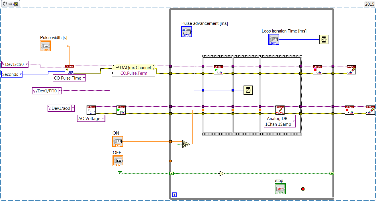
I'm trying to generate a pulse square with a NI 9263. I have tested the locking solenoids and need a pretty accurate amplitude and pulsewidth. I tried with the VI in the image. My goal is 32ms +/-1ms. This VI produces a pulse ranging from 25.5ms to 36ms. I spent the same waveform in a DAQ assistant and it was 32.2ms every time, but tripled the size of the VI. How can I get the same results with the ex-girlfriend of LV?
Create it with the daq assistant and then right-click on it and select open front panel. He complains of the vi being converted, just say OK. This action turn the express vi into a normal vi you can analyze and modify.
Mike...
Tags: NI Software
Similar Questions
-
I hope someone can point me in the right direction and also to clarify some concepts!
Background: I am currently using the box USB-6009 and labview on a laptop to output 2 analog waves. It acts as a waveform(0.5-2Hz) of speed (periodic) for an engine step by step (with a driver) to execute a loop of traffic, and the other waveform acts as a signal short 5V to trigger some imaging equipment. The ability to move or to delay the start time of the wave of 'trigger' compared to the waveform of speed in steps of hail (ms) became a requirement for my experiments. Given the time where the USB-6009 case, software based accuracy was not good enough because I need, and the way I wrote the VI limits my delay/travel at the speed of wave deltaT(30-40ms). I started to look at the USB - M series (portability is an obligation) since some have calendar based on the material, and I could send the signal to a buffer rather than iteratively having read every value of the wave in. It also seems that a digital short "pulse" works better than an analog wave form creating any. Where I ran into some confusion is to determine the requirements of a deterministic way sync the two. I am looking for new hardware. I started by looking at the box USB-6211. However, I ran across a few posts talking about the digital I/o correlated being required to perform vaguely similar configurations, which would require something more like the USB-6221. Since I have probably to the digital output to be on a time scale different analog output, is i/o digital correlated required? If not, would the 6211 work?
Just to be clear, I need the periodic waveform and relaxation to be constantly in phase (anywhere, 10 minutes to several hours). Then be able to move the pulse +/-1ms (minimum) and repeat. I can justify the most expensive device if necessary, but I don't want to get something I don't need.
I have attached a figure (not not to scale) of what I am after, in the likely event that my explanation was not too clear.
Thank you
Gabe
Hi Gabe,
The 6211 did not buffer IO digital as some of our other devices. However, there are two complete meters on the 6211 which can be used to perform a generation of pulses (pulse or continuous pulse train - you can output a pulse train using two counters finished). You can take a look at the section Applications of meter output x 621 manual for more information.
What it sounds like, the 6211 will do what you need for the following reasons:
1. the AO of the 6211 lines are buffered and can be clocked up to 250 kHz per channel (in contrast to the 6009 using AO NI by SW).
2 the 6211 counters can be used to generate two pulse based on a basis of time of 80 MHz (12.5 ns pulse width and resolution time). The 6009 does not output meter.
(a) if the two pulses must be on the same line, you must configure a task of generation of pulses finished' (this example uses two meters behind the scenes).
(b) if both impulses are on separate lines, then you can use a task to counter separated for each line with a different initial delay.
The 6211 does not supported clocked generation of digital signals (e.g. 100010101110100) but if you just need to generate impulses so that's precisely what the counters can be used to. I think that's where all the confusion, but seems like the generation of digital signals should not be necessary for your application. Trigger the counter outputs out of the trigger to start AO and adjusting the parameter 'Initial period' should give you what you are looking for. Don't forget to start the tasks of meter in the software before the tasks of the AO (if they are armed and ready to go before the start AO is sent).
I hope this helps, don't forget to post if you have any questions!
Best regards
-
train of generation of alternative pulse with USB-6251
Hi all
My goal is to generation on the USB6251 signal as output:
http://S232.Photobucket.com/albums/ee262/rusian24h/?action=view¤t=formofsignal.jpg"target ="_blank"" >
http://i232.photobucket.com/albums/ee262/rusian24h/formofsignal.jpg "border ="0"alt ="Photobucket">"


First, I marked VI "generation signal ' (attached fllowing), after that, I replaced under VI"Basic fuction generator"in VI"Multi-Fuction-Synch I-AO"(in the library of examples of Laview) with VI"generating the signal.
http://S232.Photobucket.com/albums/ee262/rusian24h/?action=view¤t=Outputanalogsignal.jpg"target ="_blank"" >
When the program runs, the output signal is last 6 periods of the signal.
How can I output the entire signal?
Please help me
Thank you very much!
Rostov,
Please use the Forums of NOR. I have seen the same behavior that you experience when you place your custom in the AI Multi-multifunction-Synch-AO VI. This behavior is because your personalized VI wasn't out the data you expect. When you wrote your data on you placed him in a graphic waveform and graphics have memory. So he was combining all data in a single chart, even though she was only being written in pieces. That's why when you place your VI in the other program that you saw only the last couple periods. I enclose a VI that I did which will display the step that you are missing, and I used one 'Add waveforms' VI to ensure that all data is saved correctly. If you place this VI in the code you should see everything correctly. Let me know if you have any questions.
I have attached the VI in version 8.6 and 8.0, if you need a later version of 8.0, let me know.
-
How to count the pulses with digital input on 6351
Hi all experts in Labview,.
I just got my USB x series 6351 and it works fine, but I certainly lack of labview skills to use it to its full potential.
I would like to read digital pulses with several digital inputs and count the number of pulses each T interval in time. All impulses that I entered on any edge of the clock are not synchronized and can occur at random times during the tests. Basically I have an oscillator of square waves can I modulate the frequency. I don't want to use the meter as inputs as I'm limited to only 2 entries (if I use the option 2 input meter for metering of pulses or frequency). The input frequency can range from 0-1 kHz and goes 0 - 3V. So not too fast, and I shouldn't make too many mistakes trying to get the count of pulses and then back out the frequency in accordance with article ni.com on counters.
I would like to read the 8 digital input channels and get the number of impulses for each channel. I searched high and low for help online but can't find examples that have been useful. Anyone have any ideas on how to go or direct me to a resource? Thank you very much in advance!
Are you worried about getting the number as a physical operation timed? It would be nice to acquire a digital waveform and then postprocess on it to detect how many events took place? I've attached an example that shows how you can accomplish this. It reads a digital waveform and then uses a detection of crete VI to determine how many pulses occurred. Should be a few adjustments to your particular signal. The VI I use seems to count events twice (probably count each edge), so counting it gives should be reduced by half in order to work.
-
Acquisition of Digital Data Output: generate a pulse with a specific width (depending on time)
How can I generate a digital pulse with a specific width? I was not able to find examples online. Thank you!
With the USB-6000 - essentially none. He has only digital software programmed according to i/o. on your system, you may be able to generate impulses at speeds up to a few hundred Hertz, but there will be a considerable amount of timing jitter. Tens of milliseconds can be common and even longer variations may occur occasionally.
Please indicate which are the times for your impulses, so someone may be able to provide recommendations specific to your needs.
Lynn
-
I need to generate 3.3 V logic level Digital train of pulses with the NI PCI-6221. Can I change the level of 6221 OR logic output?
The output cannot be changed. 5V to 3, 3V level controllers are readily available (Maxim, I think). As long as the scanning speed (etc.) is fast enough for your pulse train, even 3, 3V regulator would work. I don't know if NEITHER offers a module to condition TTL levels.
-
Generation of digital signals through external trigger pulse on PCI 6251
Sir I want by NI 6251 because I read it has the ability to generate and acquire digital signals on port 0. I want to know that can I generate external clock wave triggering (providing impulses to a line on the acquisition of data)?
Hi Ali211,
Yes, you can use a source of sample for the digital input/output clock external clock. You can connect the external clock source to one of the lines PFI (PFI0-PFI15) and specify the source clock sample like this outer line of PFI.
There are some shipping DAQmx examples that you can start with. Find the examples by clicking Help > find examples in LabVIEW.
DAQmx continually reading digital channel with External Clock
DAQmx channel External digital writing Clock
Hope this helps.
Chris G
-
Addition of a generation of finite pulse delay generates the error-200305
Hello
Sorry, I'm relatively new to the generation of pulses. Please help me understand why I get an error-200305 in my example VI Test Pulse Generation.vi when you specify an initial period. Other than the creation of a task and giving it a name, the code looks the same for me as the code in the example LabVIEW Gen dig Pulse Train - finished - Dig Start.vi comes with LabVIEW. When I enter the same settings in Gen dig Pulse Train - finished - Dig Start.vi, I do not get this error. What could happen?
I use a DAQ OR-PCI-6031E map on a 64-bit Win7Pro and am under LabVIEW 2011 (64-bit).
Thank you for your help and forgive me for a perhaps trivial question.
Peter
Hi pbuerki,
I tried the 2 screws you attached and found that if you replicate math you used in "Generation of Test pulses" for entries of the example VI, VI example will give you the same error. I think your VI and the example behaves exactly the same way.
However, I found a solution for this error. I tried this on a simulated device, but I think this should work for your physical device as well. For your DAQ card, he sometimes give you the error at very low frequencies because the default driver is the basis of time of 20 MHz and for some combinations of frequency and the number of pulses, the time base produced more ticks than the counter can handle. To work around this problem, you need to use a DAQmx channel property node. You will need to use the CO. Channel CtrTimebaseSrc property to set the time base to be DevX/100kHzTimebase. You must activate the setting 'Understand the advanced terminals' in the name of I/O filtering to find. This change should fix your error.
-
Digital output with NOR-9401 in cDAQ-9174
Hello
I have a cDAQ-9174 with an e/s digital NOR-9401 module. Now I want to output Digital signals on line0:3
$line0: Boolean 1 time = 10ms
Line1: Boolean variable 1 time = 20ms
row2: Boolean variable 1 time = 30ms
line 3:20 pulses (period = 250us, duty ratio = 0.5) after a time = 40ms
the value of line0:3 must be Boolean 0 after 45ms
Can someone let me know what I need to work to solve this please?
Thank you all for your help.
Concerning
Bing
Thank you Christian for your quick replay.
I have some experience in programming of microcontroller with C. I learned LABVIEW for about 1 month and followed a lot of demons in line and tutorials. I know that nodes DAQmx Data Acquisition screws and fundamental property.
As I said at the beginning on the $line0, lin1and line2, they serve to control the relay in my circuit. 10ms could be controlled with the OS clock. Pulse of line3 series is used for IGBT gate signals, which is the critical moment. I want to use the clock machine to accurately control line 3 and synchronize at the same time the pulse with analog inputs from an another two NI9206 modules in the same cDAQ chassis.
I just want to know more on the digital line demand signal relay output and a correlation between the line of analog input-synchronized finished pulse output. Waveform diagram is locked.
Thank you.
Bing
-
Change the width of digital pulse inside the loop
Hello
I am looking for a solution that allow you to change the width of digital pulse inside while loop.
Thanks in advance
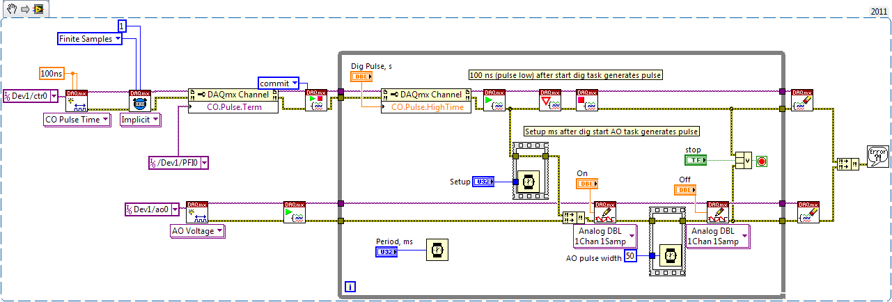
Check the operation of dataflow and single pulse meter output
First counter generates little time, then big time.
Your AO task then is to adjust tension on IT after Dig pulse. After the AO pulse width, he needs to put down
If the Trac software is small enough for you, you might have used USB-6008 ($250), not Xseries $ 1600 - apparently of an overdose. X series can do this work with a void microsecond resolution.
-
Update of digital control with different values with array function
Hello
I have attached my code base. I want to execute the code for 2 sets of digital control with a gap between the two values, then pass it. Something like that
ABC
Initialize the P1 = 10; P2 = 20; P3 = 30; P4 = 40
Run the code
delay = 10ms
Update of P1 = 150; P2 = 200; P3 = 350; P4 = 500
Run the code
jump to abc
I am stuck how can I update the values of P1, P2, P3, P4? I thought about using a function table but couldn't go further.
Thanks for the help,
Ana
Hello Ana,
One way you might achieve what you are looking for is using property nodes. These property nodes will allow you to change the values of the block diagram control. You can set up a structure of case inside your loop that will change control through nodes of property value after a certain number of iterations. Here is a community sample that shows how to use the nodes property to change the Boolean controls:
https://decibel.NI.com/content/docs/doc-22669
-Erik S
-
R507 digital camera with Windows 7
Help! I have a HP R507 digital camera with SunDisk 64 MB memory card. Recently, I updated my OS to Windows 7, the updated drivers and change the batteries in the camera. For some reason, the device's memory will not empty after that I have download the images. WHAT SHOULD I DO? CONFIRM YOUR PRESENCE! Thank you! Jim
Hello Namaycush

Welcome to the HP Forums!
I understand that you encounter problems using memory on your camera. I will do my best to help you! First of all, please let me know if you are referring to the device memory or the memory of the memory card. This changes the diagnosis a little.
Thank you for choosing the HP Forums. Have a great day!
Mario
-
3rd generation Intel® Core™ processors with Intel® HD Graphics 4000 questions
Dear HP sorry for my bad English, I have a problem on my laptop
When I played or open some game or apps there make my always 100% CPU usage, which is happen, maybe because I do not want to install the latest (3rd Generation processors Intel® Core™ with Intel® HD Graphics 4000). I get a lot of lag when played a game... but my friend with the same machine than ever
I am looking for my problem on google, but the result is emptyMy problem:
-CPU usage * always 100% when I opened a few apps or game
-J' do need a link to download the latest 3rd generation processors Intel Core™ with Intel® HD Graphics 4000 *.
-If the HP have software (support for customers) like sony (vaio care). *
I thank you very much for the reply and sorry for the bad fate
Hi DAli99GRT,
Thank you for your request, I will do my best to help you!
I understand that you have a problem with the performance of your laptop. When you play certain games the CPU usage is 100%. Looking for updates to your system.
You can run The HP Support Assistant to help with HP updates for your laptop.
You can also manually check from the HP drivers & downloads and captures your exact model by following the instructions.
How can I find my model number or product number?
Here are the documents that may be helpful. I do not know what operating system you're running, while I have provided two.
Improving the performance of the system without adding memory (Windows 8)
Improving the performance of the system without adding memory (Windows 7)
If you need more assistance, can you give us your exact model and the operating system you are using.
Results or clarification would be useful.
-
is it possible to use my pdc3070 (camera digital polaroid) with vista? It seems to be ok with windows 7.
Hi James,
(1) what exactly happens when you try to use your camera?
(2) that you get an error message that you receive?
Please provide the exact model of your device number.
Method 1: Run the fixit available in the link below
Hardware devices do not work or are not detected in Windows
http://support.Microsoft.com/mats/hardware_device_problems/en-us
Method 2: Check for any error message in Device Manager
When a device is not functioning, Device Manager also typically displays an error message with an error code that comes with it. First, search for errors in the Manager of devices to do this, follow the steps below:
(a) open Device Manager by clicking the Start button, click on the Control Panel, clicking system and Maintenance, and then clicking Device Manager.
(b) If you are prompted for an administrator password or a confirmation, type the password or provide confirmation.
(c) in Device Manager, look for the camera and then double-click the device name.
(d) If an error code has been generated, the code appears in the status area of the device under the general tab
-
Hello
I set up a lab for RA VPN with a version of the ASA5510 8.2 and VPN Client 5 software using digital certificates with Microsoft CA on a Windows 2003 server. I did the configuration based on this document from Cisco's Web site:
Now, the vpn works fine, but now I need to configure a tunnel-different groups so I can provide different services to different users. The problem I have now is that I don't know how to set it up for the certificate is the name of tunnel-group. If I do an ASA debug crypto isakmp I get this error message:
% ASA-713906 7: IP = 165.98.139.12, trying to find the group through OR...
% 3 ASA-713020: IP = 165.98.139.12, no group found by matching well payload ID: unknown
% ASA-713906 7: IP = 165.98.139.12, trying to find the group via IKE ID...
% 3 ASA-713020: IP = 165.98.139.12, no group found by matching well payload ID: unknown
% ASA-713906 7: IP = 165.98.139.12, trying to find the group via IP ADDR...
% ASA-713906 7: IP = 165.98.139.12, trying to find the group using default group...
% ASA-713906 7: IP = 165.98.139.12, connection landed on tunnel_group DefaultRAGroupSo, basically, when using certificates I connect always VPN RA only with the group default DefaultRAGroup. Do I have to use a model of different web registration for application for a certificate instead of the user model? How can I determine the OU on the user certificate so that match tunnel-group?
Please help me!
Kind regards
Fernando Aguirre
You can use the group certificate mapping feature to map to a specific group.
This is the configuration for your reference guide:
http://www.Cisco.com/en/us/partner/docs/security/ASA/asa82/configuration/guide/IKE.html#wp1053978
And here is the command for "map of crypto ca certificate": reference
http://www.Cisco.com/en/us/docs/security/ASA/asa80/command/reference/C5.html#wp2186685
Hope that helps.
Maybe you are looking for
-
adapter iPad got hot then stopped working
Hello I have an iPad Air and used iPhone 5 Watt chargers for charging. But he soon to load that I bought today a 10 Watt adapter (to an authorized Apple dealer). My iPad Air was about 52% when I plugged the new 10 Watt adapter. He began to charge sub
-
Since this morning, when I connect on Firefox, I immediately start to hear a soundtrack of pacman. In my view, it is connected to the pacman game displayed on the homepage of google. How can I stop this? This has happened Each time Firefox opened Is
-
LaserJet Pro M275 TopShot: Scanning question/icon
I use Windows 8.1 (64-bit) and I have a printer HP LaserJet Pro M275 TopShot. When I got my HP computer, I got a HP scanning icon which I could click and scan easily and also to scan multiple pages into a single document. I recently had to get a ne
-
forgotten username and password
can not connect to windows XP profrssional due to forgetfulness of password and username
-
Question of blackBerry Smartphones Email settings
In which menu can I change the setting to automatically download my mail messeges for only when I want to collect them? Thanks for advice on the subject!