MDX: Measures, County
Hi Experts,
I create calculated members or measures and I want to count all the shops that glow a certain product. We call this measure of COVERAGE. It is supoused to be able to change the territory and the product when the Manager need in the report.
I want to get (for example) the number of stores than recibes at least a bike in Barcelona and so on. Then, in Spanish territory all too.
(This is my first project, and today I keep studyng).
Thank you!!!
Xavi
You should be able to handle this by adding a member called COVERAGE with a formula in the measures dimension. Try this formula:
NonEmptyCount ([shops]. Levels (0) different, [Settings]. [A])
Tim
Tags: Business Intelligence
Similar Questions
-
I use an encoder in quadrature with DAQmx 6259, the call to read the outputs of the meter is slow, much slower than the sampling rate? No idea why?
Thank youHello Roxanne,
In the title of this thread, you mention that the calendar configuration step takes a long time. Is now called node configuration several times in your code? You may find that your code runs faster if the channel configurations and the task doesn't occur once.
Our example of the expedition, ' counting digital Events.vi ' may be of interest to you.
Can be found by browsing our example search tool:
'Help' examples
Once opened, the example Finder you can find this example by browsing:
"" material input and output"DAQmx" counter measures "County Digital Events.viBest regards.
-
How to count the digital inputs of the sensor
IImsmd MicrosoftInternetExplorer4 normal 0
I use a PCI 6221 OR-DAQ device and I want to count the total number of times that a sensor is activated. The sensor is connected to a digital line.
Tadhg salvation,
If everything you want to count the number of times where the sensor is activate, the best way to ensure this is to use a line from the meter, in the case of the 6221 try pin 37, Cnt 0 Src/PFI8. And take a look at the example of counting code digital Events.vi that you can find from the Finder example under Hardware Input and Output > DAQmx > Counter measures > County Digital events.
Alternatively, if you use a digital line, just read the line, and if the sample is true variable increment held in one register at offset, similar to the Count.vi DI attached
I hope this helps.
-
Linear encoder and configure logging
Hi all
I am currently using a surfboard with LV2010 M Series PCI-6280.
I have a linear encoder in X 4 mode connected to the counter 0 and I was wondering if it is possible to spread the values on the counter because it keeps track of the distance in a file TDMS using 'DAQmx Configure Logging'. I tried this using MAX to set this, but it doesn't seem to work, so I wonder if it is still possible that I couldn't find anything online about it.
Thank you
Lester
Hi Lester,.
My apologies, I tried on another Committee. It can work with yours, as well. There is an example of a task of counter in the buffer that should allow you to save the data by adding in the Configure logging VI as we did before.
Open LabVIEW and select help > find examples... it will open the Finder of the example. In the Finder of the example, expand folders to get to the input and output material > DAQmx > Counter measures > County Digital events > County Digital events-buffer-meter-Ext Clk.vi
Put the meter right channel and channel PFI in the controls, and then run the VI to see what he does. Then you can change the schema to add the configuration Logging VI (just as before) and rerun the VI. You will find yourself with a TDMS log saved to the path that wire you in the logging VI configures.
I hope this helps.
Kind regards
Daniel H.
-
I use a card PCI-6221 (37-pin) to count a digital signal to a flow meter over a period of 5 seconds. I use PFI 0 (pin #13).
The signal uses a pull-up resistance, connected to a power supply 5 volts to appear the signal at 5 volts during the phase of the cycle.
I don't have the power supply to the ground connected in any way to the PCI-6221 ground.
but I measured the voltage difference between the two grounds and it is only 1.4 mV.
The maximum allowed number should be about 750 in five seconds (~ 150 Hz).
PROBLEM: sometimes the signal wanders up to 1000 or more than 10,000 immediately, after 1 or 2 or 5 minutes, or the signal can not walk even after 40 minutes. I don't know, but this behavior of wandering seems to occur earlier after the start of Labview.
Any ideas?
Hi jsnyder,
Exactly how you have your signal connected? Be sure to refer to your signal to digital ground (pin 16). I would also try with an example of running your Setup program. You can find examples at help > find examples. Once the Finder example opens, make sure that the open search for it a tab at the top left is selected material input and output > DAQmx > Counter measures > County Digital events > digital County Events.vi. 150 Hz should be no problem for the meter.
-
I am currently draw a bunch of data, and I ran into a situation where some of the data are actually percentages, where the expected behavior is to other map data to a standard vertical axis that measure County but to map this percentage of data on a vertical secondary when 100% is equal to the height of the line card. Is this possible? Someone at - it an example? What I'm looking for, it's something that looks like this:
500 | 100%
| |
Coun 250 | 50% percentage
| |
0 |____________________| 0%
0 7 14 21 28
days
Thank you
JoshWow, this example has trashed when it was published.
Good news is that I answered my own question. Graphics take just load a 'secondDataProvider' and a 'secondSeries' to do.
-
Measurement error of the County of edge by using the external sample clock
Hello
I'm trying to measure the number of edges (rising) on a square wave at 5 kHz with a generator function on a device of the NI PCIe-6363. I configured a channel of County of front edge of counter at the entrance of the PFI8 device. I use an external sample clock that is provided by the output of the meter of a NI USB-6211 housing channel. If I acquire for 10secs then ideally I would expect to see a total of 50000 edges measured on the meter inlet channel. However, my reading is anywhere between 49900 and 50000.
When I use the internal clock of time base to measure the edges, the measure is accurate and almost always exactly 50000. I understand that when you use the external sample clock, the precision of the measurements is subject to noise level of the clock signal. However, I checked the clock signal is stable and not very noisy. Any reason why there is an error of measurement and how tolerance should I expect when using an external sample clock compared to when you use the internal time base clock?
Also, what is best clock Frequency (with respect to the frequency of the input signal) when using an external clock?
Thank you
Noblet
Hi all
Thanks for all your sugggestions. I was using an input signal with a function generator which had a range of 8V. It turns out that the reduction of the amplitude to 5V solves the problem. I was able to get accurate numbers with the 6211 external clock.
Thank you
Noblet
-
How to create measures of County on columns of flag in FACT with a CONDITON
I have about 6 flag columns in my table of facts, and I would like to create measures in my report with County as aggregation on these flag columns in a group by on a condition.
I am able to do this very easily with SQL query but am really stuck with on how to achieve this in OBIEE.
Each of my measure should be to make a count aggreagation in the column of flag with a condition such as true/false flag.
For example:
Measure1 - Select (INV_ID) count of payments_f of the pavilion where 1 = 'TRUE' and Flag2 = 'FALSE' GROUP_BY (COLUMN1)
Date2 - Select (INV_ID) count of payments_f of the pavilion where 2 = 'TRUE' and Indicateur3 = 'FALSE' GROUP_BY (COLUMN1)
-----
-----
similar conditions for all columns of flag.
I tried to write the where condition in the tab content of the logical table, but unfortunately it only on the level of the table - which was not very helpful for me
I'm really grateful if someone can help me on how to do this.
Thanks in advanceYou must create a new existing logical column in your logical table. Then you must set the physical mapping:
BOX WHEN FLAG1 = 'TRUE' AND FLAG2 = 'FALSE' THEN ENDS UP 1 0 OTHERWISE.
Defined sum aggregation rule.Kind regards
Stijn -
How to measure how long a Boolean value is high with thick County?
I acquire the impulse response of a parallax Distance sensor, but I I don't know how to measure the number of features that this signal is high (the time of the input signal is high is proportional to the distance). I would like to reset the counter thickness when this signal is low. is this possible? Y at - it another option?
Thank you...
for (imstuck) wrote:
You will need to adjust some if you want an indicator of up-to-date at all times.
Here is a very minimalist version which updates the timer continuously while the switch is on and holds last value when the switch is off. Try it!

-
Using measures of Dimension - COUNTY, etc... in fact results
All,
I'm running on a question that I guess is relatively simple if you know what you're doing, but I can't seem to do things. I am trying to include some counts of my Dimensions alongside my fact table measures.
For this I installed my Dimensions and the facts that I need the census to. In a simple example, I have:
EVENT_FACT
Timestamp
ID of the user
Building ID
Type of event
existing measurement = number of events
USER_BUILDING_DIM
ID of the user
Building ID
Type of building
USER_BUILDER_DIM contains a record for each user and the building, they are contained in a type. Users can exist in several buildings, so this table key is the user Id, and building ID.
When I run a query of the FACT table, I want to show the total number of distinct users in this construction next to each result. To do this, I did the following:
1. install the USER_BUILDING_DIM as a fact in my MDB, the only table that joins to the fact table is the USER_BUILDING_DIM itself
2. in the hierarchy of USER_BUILDING_DIM (DIMENSION), I have 3 levels in total, building and user... I want my account to all users for each building
3. has created a measure called User Count - separate in the table USER_BUILDING_DIM (FACT) and set it to the building of a level in the hierarchy of USER_BUILDING_DIM (DIMENSION). This is the only level that I put for this measure
When I go into the answers, and I create a query like:
ID, number of events, the number of users - separate from the construction
The query comes back perfect shows me the number of total events of the EVENT_FACT table for each building, and beside the number of distinct users for users in this building from the USER_BUILDING_DIM table.
The problem occurs when I add all the other dimensions in the application that hang off the table EVENT_FACT, as months of my time Dimension that also blocks out of the EVENT_FACT table:
Months, the number of events, the number of users - separate
Now for the above query the number of users - separate value returns nothing and when I look in the logs of replies does not even a count more and joins the place just to the USER_BUILDING_DIM in the EVENT_FACT table and the Dimension of TIME
Any thoughts... Thanks in advance
KI guess that this will solve your problem. Just a guess.
go to your fact table of the building and the content to set the level for all other dimensions with the highest level available for these dimensions.
-
Simultaneous digital writing and reading w. measurement interval
Hi all
For the last couple days, I've been trying my brain trying to get a program to run.
I am trying to generate a camera digital 4 output bits then simulatanously count edges mounted on its LSB up to an arbitrary number set by the operator of the program, how the program should be a measure.
I note, however, that, on a certain edge County number growing (~ 950 or almost), the program crashes. The problem persists even when I remove the function that reads the LSB, although, in this case, accidents occur to a much higher number. What could cause this? Is there a way I can work around this problem?
Here is my code:
arraySizeInBytes2 = 8
bufferSize = 255ReDim readArray (arraySizeInBytes2)
publicLifetime = 100' use this to control the duration of the task takes
numSamplesToWrite = 10 * publicLifetime * numSample * 5
numSamplesInArray = 5 * 10 * numSample"the code that sets the analog and digital output signals
j = 0
k = - 1
<>
If SampPerCycle Mod d = 0, then k = k + 1 other k = k
For m = 0 to 3
If ((k) and (2 ^ m)) = (2 ^ m) then writeArray (m, j) = 1 Else: writeArray (m, j) = 0
Before m
j = j + 1
LooppublicStatus = DAQmxCreateTask ("", taskHandleDigitalOut)
publicStatus = DAQmxCreateTask ("", taskHandleAnalog)
publicStatus = DAQmxCreateTask ("", taskHandleDigitalIn)
taskIsRunning = TruepublicStatus = DAQmxCreateDOChan (taskHandleDigitalOut, "Dev2/port0 / line0:3","", DAQmx_Val_ChanForAllLines ")
publicStatus = DAQmxCfgSampClkTiming (taskHandleDigitalOut, "Ctr0InternalOutput", # 1000000, DAQmx_Val_Falling, DAQmx_Val_AcquisitionType_FiniteSamps, numSamplesToWrite)
publicStatus = DAQmxCreateAOVoltageChan (taskHandleAnalog, "dev2/ao0","",-10, 10, DAQmx_Val_VoltageUnits2_Volts, "" "")
publicStatus = DAQmxCfgSampClkTiming (taskHandleAnalog, "Ctr0InternalOutput", # 1000000, DAQmx_Val_Falling, DAQmx_Val_AcquisitionType_FiniteSamps, numSamplesToWrite)
publicStatus = DAQmxCreateDIChan (taskHandleDigitalIn, "dev2/port0/line7", "", DAQmx_Val_ChanPerLine)
publicStatus = DAQmxCfgChangeDetectionTiming (taskHandleDigitalIn, "dev2/port0/line7","", DAQmx_Val_AcquisitionType_ContSamps, 8 "')
publicStatus = DAQmxWriteBinaryI16 (taskHandleAnalog, DACwaveFormSize, False,-1, DAQmx_Val_GroupByScanNumber, buffer (0), sampsPerChanWritten, ByVal 0 &)
publicStatus = DAQmxWriteDigitalLines (taskHandleDigitalOut, numSamplesInArray, False,-1, DAQmx_Val_GroupByScanNumber, writeArray (0, 0), sampsPerChanWritten, ByVal 0 &)publicStatus = DAQmxStartTask (taskHandleDigitalIn)
publicStatus = DAQmxStartTask (taskHandleAnalog)
publicStatus = DAQmxStartTask (taskHandleDigitalOut)
publicStatus = DAQmxStartTask (publicCounterHandle)r = 0
< (publiclifetime="" *="">
publicStatus = DAQmxReadDigitalLines (taskHandle, 1, 5, DAQmx_Val_GroupByScanNumber, readArray (0), arraySizeInBytes2, SampsPerChanRead, numBytesPerSamp, ByVal 0 &)
If publicStatus = 0 then r = r + 1
If r Mod publicMeasurementInterval = 0 Then ' measure Code here
LooppublicStatus = DAQmxStopTask (taskHandleDigitalIn)
publicStatus DAQmxWaitUntilTaskDone = (taskHandleDigitalOut - 1).
publicStatus = DAQmxClearTask (taskHandleDigitalOut)
publicStatus = DAQmxStopTask (taskHandleAnalog)
publicStatus = DAQmxClearTask (taskHandleAnalog)
publicStatus = DAQmxStopTask (publicCounterHandle)
publicStatus = DAQmxStopTask (taskHandleDigitalIn)
publicStatus = DAQmxClearTask (taskHandleDigitalIn)
taskIsRunning = FalseThank you.
You were right: it was a buffer overrun. I was using integers when I should have used doubles.
Thank you for your help.
-
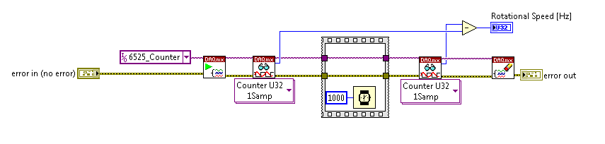
With the help of the meter from 6525 to measure the frequency: is there a more orderly way?
I am currently using the high speed on a module USB 6525 meter to measure the frequency of an object in rotation via a sensor hall-effect.
I was wondering if there was a simpler way / more effective this encoding than that?
Everything that I currently perform the current meter reading, wait a second, take another reading, and subtract one from the other. The result is the frequency in hertz.
Is there a way to get the 6525 to return the number / change County after 1 second?
Thank you
On the 6525, you have a country of the event and you can't make a measure of frequency.
-
By train and failing to carry out measures of speed
Can someone explain to me how the linear speed CI module is supposed to work? I tried with no successt for a while to use it to take measures to speed by using a meter. I use a card NI 9411 digital input to accept a signal from a radar system which shows a maximum speed measured as a frequency (which is just working at a rising every 0.176 inches moved).
Whenever I run VI I get an error in the module create channel which is as follows:
Code:-200431
Source: DAQmx create channel (CI-linear velocity) .vi:2530001
Property: CI. MeasType
asked the value: Speed: Linear encoder
Possible values: Frequency, period, pulse width, period of Semi, separation of the two sides, pulse frequency, pulse, Pulse ticks, Position: angular encoder, Position: linear encoder, edges of CountyThe task name: _unnamedTask<6>
That, on a subject similar, is there any where a document that lists the module chassis DAQ and DAQmx measurement compatibility? Because I do not find that documented anywhere it's obvious...
Well so be it... I finally found a document that lists the compatibility of type of measure and appearently the only module able to do using the virtual channel of speed measurement is the 9361 OR...
-
Card required for control special measures
Hello!
We have some NOR-DAQ cards (PCI-6221, 6251 and 6036E) but none of them seem to be capable of the following measure.
There is a digital pulse train that must be received (practically with a meter). To measure the VOLTAGE to a channel of AI when a pulse is received. The frequency of the pulses can be 1 KHz, therefore generating events at each pulse for the PC is not viable. He must also know where the pulse OCCURRED (something as the card should have its own clock and should be able to put next to the measured voltage value).
In addition, the map should give a sign of output (pulse change or line) of 1. the number of pulses reached a given amount or 2. the voltage is lower or exceeds a value given to a channel to HAVE. If an automatic output is not available at least we have an event to the PC.
Will there be any card to fix this? In fact the card must have at least two meters since we have two trains of digital pulses, but only is active to a degree. Thank you very much for your suggestions!
Could you clarify it please ", we have two trains of digital pulses, but alone is.
Active to a degree. You check in for a number of pulses on several lines? You have more than one channel of Analog Input?Without taking into account the requirement for the 2nd train of digital pulses for the moment, to my understanding of the application the 6251 could do you need:
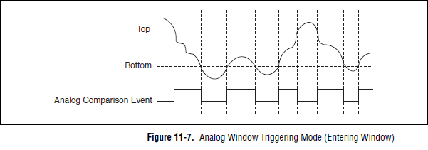
1. the signal of AI must be connected to the 6251, since it is the only one of the three that supports analog trigger.
You need to configure an analog reference trigger to allow comparison shipped. You can use the line to HAVE it if you are sampling just one channel (or an APFI line if you're sampling from multiple channels). Export event of analog comparison will tell you when the signal is outside a certain threshold (the graph presents 'Entering the window' but you can select "Exit" instead):
2. connect the Digital pulse train to one of the PFI lines on the 6251. It will be the sample for your task clock to HAVE.
4. use the same PFI line as a source for a meter (pulse) output task. Set the initial delay so that when the desired number of pulses have been counted you will produce a pulse on the output of the counter.
5. you now have a line telling you what N pulses have been reached (from step 4) and a line telling you where I is outside a window (in step 1).
6. If you want to timestamp pulses using the edge of the Office counter, you must use the counter 2nd as a county of edge stamped with the external pulse as your sample clock signal. This will give you a very precise timestamp of your external impulses (compared to the beginning of the task).
If you need for impulses of timestamp on multiple lines, you can look in the task configuration of change detection of DI on the 6251 and using change detection event as the sample for the task of counter clock. You must implement logic in SW to determine which line has generated the actual event.
You have also 4 other counters to play with on your other DAQ hardware two, so depending on what you want to do, you should have a little flexibility.
Best regards
-
High speed continuous measurement of encoder with sampling frequency of 1 kHz
I am able at all times the position of a linear encoder using a PCI-6602 counter card, and I need to know how to set up so that the counter rotating at high speed, but the data is inserted into the buffer at a frequency of 1 kHz. I am able suddenly to a hydraulic cylinder, and I am not concerned about the event recording to high frequency except to the extent where they throw off the number considerably if the equipment does not run fast enough to detect all the impulses of the encoder.
Now, I think is that the external sample clock signal control (routed internal pulse output counter) time rate whereby the equipment detects the impulses of the encoder and the rate at which it inserts data into the buffer. With a pulse 100 per inch encoder and a sampling frequency of 1 kHz, the extended final position of the cylinder is turned off by +/-0.15 inches, which is unacceptable.
I need calculate a speed of this information, so I prefer not to use software timed sampling to control this (it's more difficult programming for other reasons as well - several asynchronous measures). Any ideas on how to configure the hardware to count faster than the speed at which she inserts counties in the buffer?
OK, you're clearly on the right track here, so I will focus on some details.
1. How do you know that the +/-0.15 "differences are * measurement error rather than * error of movement? Why wouldn't be an accurate measure and a proposal which can vary slightly from the nominal value?
2. I wonder some all electric noise and defects that may produce false edges. The fact that the behavior was better by using a sampling rate limited (200 kHz) in the digital inputs may be that some of these flaws were so short that they were never captured.
I did a ton of work with the Commission to 6602 encoder and I can certainly confirm that count equipment is sensitive to the edges in a few tens of MHz. (I know its 80 MHz for edge counting, but I think I remember that it can be of the order of 20 to 40 MHz to accommodate the time of signal propagation extra of the quadrature decoding circuit).
A small point of clarification. You're talking about the speed at which the meter "works to. The value of count is a register whose value is changed completely by the circuit, * independent * of the sampling frequency. If you enjoy with material-clocked County in memory buffer or interrogation of software without buffer not a bit for circuits that increments / decrements the value of the counter register. (In other words, I am completely convinced that you would get commensurate with position end even if you took only 1 sample software-polled after the end of the move instead of sampling at 1 kHz all the way through.)
So, if the value of the counter is disabled, it is because the circuit detects producers of County of the edges that shouldn't be there. Something you can try is to set up digital debounce filter for input lines of the PFI corresponding to the encoder Source inputs and to the.
-Kevin P.
Maybe you are looking for
-
I don't want to lose what is already there.
-
Fake Web report loses the URL if you fail the quiz first.
Windows 7 - Firefox 22-23 (perhaps earlier too) If you make the answer, firefox will refresh the page with new characters, but in the process, loses the offending URL. i.e. 1st time"URL ="http:/domain.com/phishingsite"txt = "mistype (123)" "Enter = "
-
All, What version of the SNMP protocol use the TMS between endpoints & infrastructure products? Is there a way to force the TMS to use v3 and disable v1 & v2? Thank you Justin FerelloTechnical Support SpecialistKBZ, a Cisco authorized dealer http://
-
Dell U3014 Rev A01 Scanline problem and translation mistake...
Hello holy chrism. first of all, I'm of the Germany so I have postet several times the problem in the German Forums isuess, but there is no response... I'm here now. I have a dell u3014 rev 1, I have two Points, I have the problem of scanline too and
-
What update for cs3 is compatible with windows 10
What update for cs3 is compatible with windows 10?