measure the State of the output to USB-6525
Hi, is it possible to check the status of microsatellites in a USB-6525 using a multimeter. I hooked up a meter to measure the resistance through the P0.0A and P0.0B output connections. I wanted to use the automatic test routines to check the SSRs were closing. As expected, there was an open circuit when LIFE expectancy was 0, but the circuit seemed not close when I changed the TTL of 1. Do I need to connect to a power source and load to be able to see the closing SSRs? Is not which is what a multimeter?
Thank you, Nick
Nick,
Multimeter will not provide the source of tension and support you need. Check out this link. http://digital.NI.com/public.nsf/allkb/B0FF01B2AFFA52FC862573A2005A9570
Tags: NI Hardware
Similar Questions
-
How can I measure the output of a sensor pwm ultrasound using the module or 9403
How can I measure the output of a sensor pwm ultrasound using the module or 9403
Khalil,
When you say 'measure' the PWM signal, exactly what to tell you?
You're looking to measure the frequency or cycle of the signal function? You count the edges of the PWM output increase? Looking to control the waveform?
With reconfigurable FPGA hardware, it is up to the user to define the function of the physical i/o on the FPGA chip. By connecting the signals as Adam suggests your digital pulse will be brought to the cRIO. In your FPGA program, you define the function. You can set a base counter or transfer digital data from single point to welcome you cRIO for floating-point more complex treatment. Example FPGA programs are located in the http://www.ni.com/IPnet.
Hope this helps, please post any additional questions.
-
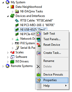
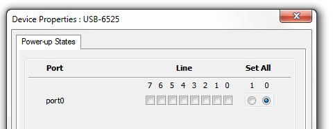
State of relay by default USB-6525
Hello
When the NI USB-6525 enclosure is powered on the default state to solid state relay is closed. I'm trying to use it to control a 4 position RF switch. Obviously we do not want to be on as this disrupts the 4 switch inputs.
Is it possible to change the default state of the relay, so that when the device turns on the relay are all open rather than closed?
Hi SeanJ,
Sorry for the delay on this point - I just noticed this post by searching for clients who may have encountered this problem.
From DAQmx 8.9, programmable start-up States have been added to the USB-6525. However, flash on these cards was not initialized correctly to 'open' State, so the check for PPS caused tips have added a default PPS to 'closed '. The solution is to simply set the States start to their desired state. This can be done through MAX as follows:
All the councils that are currently on the market have their flash correctly initialized to the open State.
To reduce the risk of this question anyone adversely affecting during updates, we also add a check for the firmware in DAQmx 9.2.2 and later charger to initialize the flash if you are upgrading a version of the driver without PPS. If the upgrade to a version of the driver with PPS, the startup States will not be affected.
More information can be found here:
Behavior of the start state Programmable NI USB-6525
I apologize for any inconvenience that you please do not hesitate to let us know if you have any questions.
Best regards
-
Is it possible to a floating voltage with the output box usb-6009?
Hello
I was wondering if anyone knows how to a difference in voltage output 0 to 1 AO on the box USB-6009 DAQmx AO without reference to the ground. Any help would be greatly appreciated.
Thank you
Bryan
Hello
Page 19 of the manual USB-6009:
http://www.NI.com/PDF/manuals/371303l.PDF
Shows the internal circuits of the DAC are referenced to ground so there is no way to internally isolate it / provide any reference.
Maybe there is another way to make the desired effect? I don't know the details of your request to suggest everything.
Please do not hesitate to ask questions
-
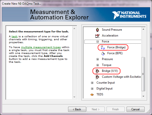
How do I capture the output of voltage full bridge with Signal Express NI9219
Hello. I'm trying to do and calibrate a load cell with the installation of full-bridge strain gage. I use a NI9219 module with a cDAQ chassis. Is it possible to capture the actual output voltage? Signal Express gives me a value of strain, but I really need to know the output voltage. Where to look. I need only two channels for full-bridge. I think that could connect the wires to the two remaining channels and read the output voltage of the strain gauges which would be connected as a tension of the 9219 entry, but I think that Signal Express could give me the voltage and output voltage directly. Any input would be appreciated. Thank you! P.S. I only use this equipment on occasion and am not the more familiar with it, so keep things simple for me. Thanks again.
Hi jgh@AET,
The NI 9219 measures the ratio of voltage full bridge in hardware sensors, allowing any variation of the voltage to cancel. You won't be able to measure the output voltage of the sensor regardless of the voltage without additional channels, but you can measure the ratio of raw tension using the type of Bridge (V/V) . You can also use the type of measure of Force (bridge) measurement of load cell with engineering units (N, lb, kgf, no strain).
This screenshot shows where the two Bridge (V/V) and Force (bridge) can be selected in the DAQ Assistant:
These types of measurement were added sometimes around DAQmx 9.1, so if you have an older version of NOR-DAQmx, your DAQ Assistant maybe not them. The latest version is currently 9.4 of NOR-DAQmx. Front of NOR-DAQmx 9.1, the approach to recommend to measure the load cells was to use the custom with Excitation voltage type and a custom scale. However, Tension Custom excitedly can't Bridge of calibration in the DAQ Assistant.
Brad
-
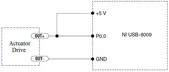
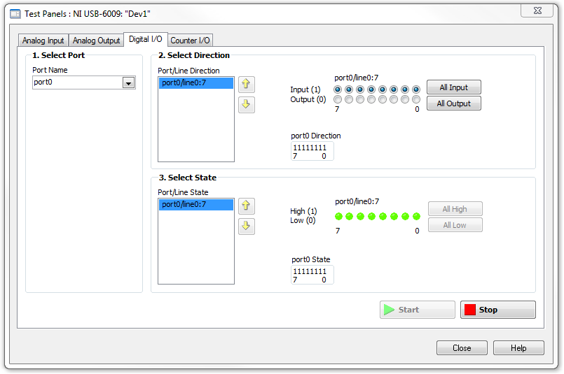
How to measure the digital output of the linear actuator on USB-6009?
Hello
I am a new user of Labview and need help to measure a digital input signal.
I have an actuator Bimba Original line electric with a motor continuous integrated with encoder, drive and the controller. The drive has a programmable digital output that I put as a tachometer output that emits pulses of square wave 100 per turn of the engine. I put the engine to make a total of 56 rev in 22 dry. I want to measure the speed of motor rotation labview real-time and synchronize it with a few other analog input signals. I wired the actuator for the USB-6009 case as shown below.
I opened the test i/o digital USB-6009 Panel and fix all the lines of port 0 as inputs. However, when I click on start and run the actuator, p0.0 led flashes, as indicated below.
Shouldn't the led blink in response to revolutions of engines?
I want basically to collect the drive pulse signals and convert them in rpm on labview.
ahsan2 wrote:
I have it wired correctly?
It would help if you do not attach the HIGH signal. Remove the + 5V in the circuit.
-
Change the output state if the connection is lost
Hello
I use a multifunction USB data acquisition system - 6341 XSeries to control an experience involving a heated hose. I use MATLAB to read a number of analog sensors, and output digital to activate the relay to control certain devices of heating and a pressure relief valve. My problem is if I lose power, someone throws a cable or my computer crashes Mid-test, I want the relay to turn off (IE, return all the digital outputs 0), for reasons of security.
I figured out how to make the default value to the output power up to 0, but I did not find anything describing how to do the same thing if a connection with the computer is lost. Is there a property inside the acquisition of data that I can program to do something like that?
Thank you
Jimmy
The 6341 timer has a built-in digital i/o which is mentioned in the X series user manual in Chapter 6 (pdf link).
You reset the watchdog timer of your software loop - if the timer expires the material past to a predefined State.
I have no idea how it is configured in MATLAB, but in the C API functions used are DAQmxCreateWatchdogTimerTask to create the task and DAQmxControlWatchdogTask to reset the timer.
Best regards
-
Measure the time of the rising edges of a digital stream using a USB-6341
I have a DAQ USB-6341 map.
I use Measurement Studio (writing code in c#) on a Windows 7 computer.
I'm relatively new to the DAQ cards, programming, so I could ask something that is obvious (sorry if this is the case).
I went out a stream of digital pulses to an analog output channel. I wired this channel to one input of the meter channel. I am able to measure the number of edges upward to the inlet of the meter channel (since the digial flow is continuous, the number of rising edges increases with time).
I would like a time stamp of each rising transition and I like to keep these timestamps in a table without ever growing (or maybe bin these timestamps in a histogram).
Set up the meter channel to provide the timestamp data? (rather than just count)
Thank you for your help.
WRB,
The meter must be able to measure the relative time between the different edges of your signal. To do this, you will take care to set the meter to measure time. It will measure how long a full period of your signal takes. You can configure edge that you want to start with. You'll want to set up your timed 'implied' measure. This sets up the meter to automatically take action whenever a period is over. While it's not exactly a timestamp, you can find the distance between two edges by adding the time periods between the banks in question.
I see another technique that you can use. This would put the counter to edges of County one of the basics of time of your device (it has 100 KHz, 20 MHz and 100 MHz bases long). Then configure the task to use your signal as a sample (configuration to use rising edge) clock. Whenever the song occurs, you will get the number of ticks ticks selected timebase that took place at that time. One thing to note here, however, is that the counters are 32-bit wide, so your code will have to manage the overthrow of this charge if you are using a fast time and base running for long periods of time.
Hope that helps,
Dan
-
Basic measures and the output impedance of the change with PXI-4461?
Hello
I am required to build an audio station with platform PXI OR test.
It is my first experience with Renault. So I don't really know a lot...
The PXI-4461 is a replacement of a former HP audio Analyzer. The measure is quite simple:
1 generate fixed freq signal and measure AC RMS power
2 measure THD (total distortion harmic) at frequency fixed
3 measure SNR (signal to noise) at frequency fixed
4 generate and measure DC signals
5. change the output impedance of 50 ohms and 600 ohms.
If I have a good feeling on which tasks 1 to 4 are feasible. I would like to ask if the task 5 (change the output impedance) problem possible?
If this isn't a work around?
As for tasks 1 to 4, it is possible with out doing 'a sound vibration' Toolkit?
How helpful the Toolbox will be for the tasks listed above (humble).
What should be my starting point learn to manage these measurement with Labview?
Thanks in advance
Hi Hazkel,
Sound and Vibration toolkit will help a lot with steps 1 through 3. This without the Toolbox would require a very high level of knowledge with LabVIEW and you will probably run again for complications. In response to the fifth step, I tried to adapt the output impedance and am not able to do so programmtically. However, you can still do this in hardware by adding a shunt resistor and potentially switch between if necessary impedances. We have an article that deals with impedance matching and a circuit configuration to set the impedance if you are interested:
Impedance and impedance matching
http://www.NI.com/white-paper/3475/en/
I recommend starting with examples that we have already built in LabVIEW to familiarize yourself with the concepts. You will find them by clicking on help-> find examples-> search, then search for your application. Please let me know if you have any other questions.
Thank you
-
Hallo,
I use the following system:
- OR PXI-1044 with controller NI PXI-8109
- OR PXI-2564 switch module to turn on the monitor of my test device
- Data acquisition multifunction NI PXI-6259 to measure the signal that responded to the questionnaire jump
The two cards are the same - PXI trigger bus. For both, PXI-2564 and PXI-6259 I use DAQmx to set the reading and writing of the channels.
Now, I want to measure the time between the digital output, my unit turns and the analog input, which measures the response of my system.
I can't do work by myself, please help me!
I thank Ludwig.
Hi Ludwig,.
If you can't give us any VI we have difficulties with to help you.
Because I Donat knowledge how your program is mounted it is not easy to know where you should enter signals.
Here's a question similar to yours:
http://forums.NI.com/T5/LabVIEW/best-way-to-measure-time/TD-p/178704
and 2 external links:
http://www.ehow.com/how_8698983_measure-time-LabVIEW.html
http://objectmix.com/LabVIEW/385152-how-can-i-use-LabVIEW-measure-time-between-analog-pulses.html
-
Sampling frequency for the output of an acquisition of data USB-6211 card?
Hello-
I use a CGI CMOS FireWire camera to read an interference figure, then using a transformed of Fourier transform spectral interferometery (FTSI) phase recovery simple algorithm to detect the relative phase between the successive shots. My camera has a linear 28 kHz scan rate, and I programmed my phase retrieval algorithm take ms ~0.7 (of a trigger of camera at the exit of the phase). I use the live signal to control a piezoelectric stack, by sending a voltage single sample to the analog output of a data USB-6211 acquisition card.
Send this output voltage increases the time of my loop 4 m, I would really like to achieve a 1 kHz or better sampling rate. Is the problem with my DAQ card or with the processor in my computer? The DAQ cards of NOR can support these speeds?
Thank you
-Mike Chini
Hey Mike,
With USB, your loop rate will be around or under 1 kHz, even on the best of the systems. USB has a higher latency and less determism PCI and PCIe. You can get rates AO one much better sample on a PCI card, potentially a PCI-6221. We have a few HAVE points of reference for targets of RT for PCI, / AO in a loop, you should be able to get similar performance in Windows, but if you do a lot other treatments may suffer from your local loop rates.
Hope this helps,
Andrew S
-
It is current on the analog module USB NI 9263 output voltage limit (+/-10 v)?
It is current on the analog module USB NI 9263 output voltage limit (+/-10 v)? I try to run a current controlled resistance, but cannot get the required current. The servovalved has a parallel internal resistance of 80 ohms and requires 20 my full operation. Ohm's law: (.02 A) * ((80*80) /(80+80) ohms = 4.5 v) Yet, the required voltage, do not move the servo. Outside the material error (continue this by other means), what could be the problem?
Have you checked the Manual?
Page 12 1 says my.
For servo, you really need some kind of amplifier. See if the manufacturer provides the electronic driver for it.
-
How to synchronize the analog input and the output of two different USB data acquisition boards
Hi all
I have two tips very different USB NI USB 6008 case, which I use to acquire the data (analog input) and a USB of NI 9263 is a output analog only site I use to route a signal (in this case a square pulse). The reason why I use the outputs analog 6008 is because I need to deliver negative tension and need the full +/-10 v range.
Looking at similar positions, I'm pretty sure that I can't use an external trigger or a common clock, I also tried to use the timed synchronization of the structures but no cigar.
I'm including a quick vi I whipped showing how the jitters because of the lack of synchronization signal. The OD of the 9263 connects to AI in the 6008 in this example.
I talked to a specialist in the phone and tols me that's not possible.

-
USB 6525 6501 digital for output to the step motor
Hello
I try to use USB 6501 or USB-6525 out of step motor signals which command the stepper motor. My questions are
(1) do I 6525 USB, I'm not sure the function of it (perhaps as a relay).
(2) now I connected input 5V for USB-6501 "+ 5V" pin and GND to pin "GND". On the other side (output side), I connected ' enable '(from motor drive) to P0.0. 'direction' to P0.1 and GND to GND. Can I use the express signal to test, the error says "lack of entry."
(3) I guess the next step is programming labview. Does anyone know of similar examples?
Any help would be appreciated!
Melody,
If the engine must input external logic level I advise to use the USB-6501, which is just a digital I/o card. The USB-6525 housing does not have the digital outputs to control your motor drive. If I understand correctly you just try to turn the motor on and off with a digital signal. It seems that you also provide your drive motor + 5 v and GND. The USB-6501 has channels for + 5V and GND. I've attached an example of navigation that controls the outputs digital using DAQmx and LabVIEW. This specific programme allows to control 8 digital output lines, but it looks like you don't have one. If the engine waiting for you just a strong to put logic in operation and a logic low to shut down this program example will be able to turn on or turn off your engine. Just connect one of the USB-6501 digital output lines and then use the program to this line of control.
I don't really know any reason, you need to use the USB-6525 it seems to me that the USB-6501 run action you need. I hope this helps.
-
How stable is the long term outputs analog USB-6008?
The USB-6008 datasheet do not specify the stability long term of the analog inputs and outputs.
I'm looking for stability compared to the ambient temperature and time (several months to a year), mainly for the outputs or the D/A reference voltage.
Is there any information available?
Thank you.
The precision specification takes into account the evolution both because of the temperature and duration (stable). Thus, for the period of a year that we guarantee these specifications, which list you is correct. However, apart from the period of one year since the calibration, this specification may be is more inaccurate.
Maybe you are looking for
-
will not get my ipad mini 2 ios 10
Hi im having this problem. I bought my mini ipad 2 in 2013 and it is ios startup was 5th and now his last 9.3.5. and it won't give me the latest ios 10. What is important to what ios your device began with? because I have a picture where it says it m
-
Pavilion G7-2276SA: formatting of HP Pavilion G7-2276SA
I bought the HP Pavilion G7-2276SA in December 2012. He had Windows installed in 8 and I had upgraded to Windows 10 when there was an available free urgrade. I want to format my laptop now, and I suspect that the laptop back to factory settings l for
-
I just bought a new dv7 - 7227cl with 8 windows pre installed, I have an ssd (Crucial CT064M4SSD2 M4 64GB 2.5 "SATA III) I'm trying to install in the main hard drive and move that he arrived with a secondary drive, how can I reinstall windows 8 on th
-
timestamp to the number function
The range of functions and Conversion screw has a function that converts the number of seconds passed a time stamp (To Time Stamp Function). I need to go the other way, a duplicate timestamp (number of seconds since midnight, Friday, January 1, 1904
-
Hello I just bought the printer 8640 and the ADF scanner simply does not work. If I put a document two faces in the ADF and the scan it just comes up with a blank white page. Don't worry I'm not stupid enough to have the document backwards as I have