Model linear and model discrete?
I already have a linear model in the form of State-space for my implementation of MPC,
How to convert a discrete form to be used for the implementation of the MPC, because it requires
a discrete state space form?
Hi Barp, altenbach and everything...
I am writing to give the details of my interest in implementing
a MPC controller for a four-tank process.
Attached is my VI and a note with the details, please how is the
Discretization put in place... I hope to have the VI return after discretization.
Best regards, Vicky.
Tags: NI Software
Similar Questions
-
How to choose between a linear and logistic model in the regression of the glm?
Hello
documentation, I learned that the algorithm of glm for the linear regression model supports linear and logistic regression. However, I can't find any switch or parameter that selects one or the other. How can I tell ODM what kind of regression I want?
Thanks in advance!
Hi Bernd,
Here are some additional tips.
Hope this is what you are looking for.
THX, mark
If you specify a classification, it is logistics. If you specify the regression, linear regression. Logistic regression only we offer is the variance and binary logistic regression canonical link. If you have a target with values in [0,..., 100] and you want to use logistic regression of glm, and then create a view that selects a share point, for example, 50. There is no parameter variation algorithm.
Create view bin_v as
to select which target< 50="" then="" 0="" else="" 1="" end="">
var1, var2,... varn my_data.
Otherwise if you want linear regression, specify regression and let the data it is.
-
How to distinguish between linear and radial gradients in Javascript
Hey guys,.
I noticed that some some scripts im using cant always target linear and radial gradients. I was curious to know why it was and where the information about the time a linear or radial gradient is stored or how it can be accessed. So far, no luck.
That's what I have so far, it doesn't tell me anything besides a pathItem given has a "GradientColor." as fillColor is, I can not understand the syntax to test whether it is linear or radial.
#target illustrator
var doc = app.activeDocument

for(x=0; x<doc.pathItems.length; x++){
alert (doc.activeLayer.pathItems[0].fillColor);
}
I tried to fix at the end but there always indefinite returnes.
.Guy
. TypeName
.gradient
. GradientType
and another thing I could find in the CS6 refrence guide.
Advice or direction would be greatly appreciated.
you're close, you need to target the real gradient object to get its properties
alert (doc.activeLayer.pathItems[0].fillColor.gradient.type);
-
Sorry, but I'm still pretty new to LabVIEW and NI MAX I plugged the two devices (a linear probe and an angular encoder) for my NI 9401 chassis. I figured out how to create tasks for each and continuous readings of samples of each. Trying to run both in LabVIEW, I get the error message saying that I can't run several tasks at once. He suggests the control task VI, but I did not see any help. Any advice?
Here is some general information, whatever it's worth: two encoders work the same clock source, PFI4, which, to my knowledge, is the CTR 1 A, where the the angular encoder signal is wired in. Physical channel linear is ctr0 and the angular is ctr1.
Thank you very much for taking the time to review this issue and help me out!
-
FIRST HP: Deviation average and a discrete random Variable probability Distribution
Hello
Can comeon please help me with the calculation of the average and standard deviation of the discreet following random variable probability distribution.
* k = 0.14
I would like to the average and the standard deviation of the number of people per car.
I used the 'statistics 1 VAR App' and I entered in the following:
When I click on 'Statistics', the following text is displayed:
Responses (rounded to two decimal places) for the mean and the standard deviation should be:
Average = 3.67
SD = 1.31
It seems that the statistical calculations are based on the column "D1" only.
Is someone can please show me how I can put the statistical calculations to include the data in the columns "D1" and "D2"?
Thank you
Arthur
I solved my problem.
I read the pdf document "HP first AP statistics Summer Institute ' and it explains how to use the app from Var Satatistics 1 more in detail.
Concerning
Arthur
-
CS6 and custom curve Point as opposed to linear
Then when I opened a new D700 shot in ACR with CS6 and go to the point curve Panel he customized the default value. That seems to have about 10-12 points on it and looks like it provides a slight lift in the shade and a slight decline in light tones. I can choose linear and I don't know how to save the new default, I'm just curious what the curve Custom is and whence it. I use the neutral profile V.4 If that makes a difference.
I have not seen that this mentioned anywhere. Anyone he understand?
PIXIllate22 wrote:
What was once a curved point linear linear labled is now a curve of medium contrast labelled and designed to appear as a linear curve point.
It is not a psychological problem. The fact is that there is now a hidden curve for linear curve point labled setting.
Laughing out loud. It's more a psychological problem... the linear tone in the previous 2010 PV curve was NOT a real linear curve. It was still a modified gamma curve is same that adjustment was mild. If you set the PV 2010 tone to contrast and brightness linear curve and set, you'd come closer to a linear rendering but he had a non-linear gamma adjustment because she has been standardized for display and adjustments. Some people fell in love with the low contrast material, starting point. Some people also reserved to point curves and no base Panel setting. This is not an optimal approach now with PV 2012 because it ignores a lot of tone mapping the new base Panel can do.
You can use DNG Profile Editor to edit a DNG profile for your camera and return to a more linear (not perfectly linear, only more linear) if that's what you want, but you can not do with any command in LR4/ACR7 now without getting the exposure settings and negative and several contrast curve of you pointson to set the new default curve is more linear (but still not exactly linear).
As to why they converted the old medium contrast and defined now as a linear curve by default, which was to have no curve reference located in the default of the ACR/LR so that the curves could be applied to raw, tiff and even 32-bit images comma floating and use the default even starting point. The standardized medium contrast curve still lives in the DNG profile and this is where you change the middle to linear curve in a custom profile of DNG. Bottom line, the largest well is the mobile... some people do not like change, but they will not change because the people who don't like it are a tiny minority.
-
Representation of State-space Discrete in FPGA
Hi all
My goal is to simulate a State-space model is the FPGA cRIO (order to use an observer).
I am currently trying the simulate on my computer without using the VI state space discrete Control Design and Simulation Toolbox (since there is no model of State-space for the FPGA VI). However my representation of the discrete state-space model does not work.
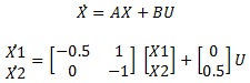
It is under a continuous state space model:
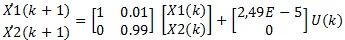
Then I got the model discretized (using the zero-order-hold and t = 0.01 s):
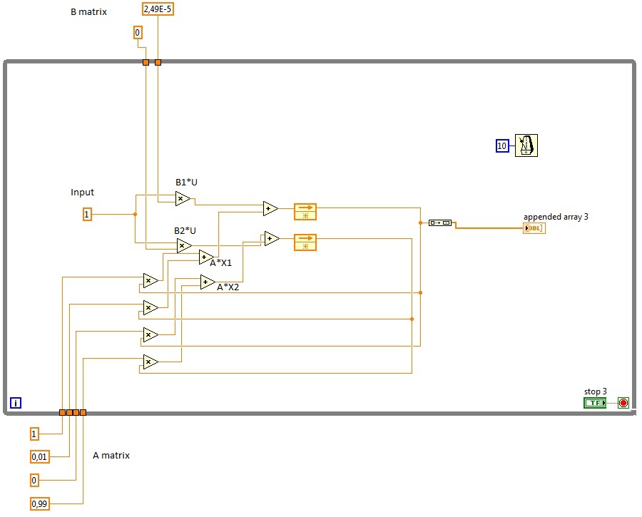
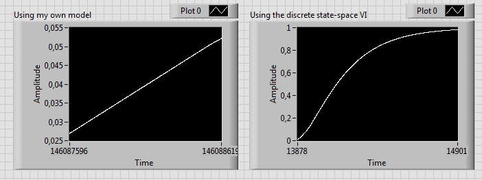
Here are the State-space discretized model I designed (to develop a similar model in the FPGA):
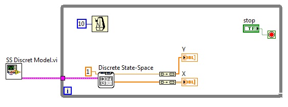
This is the VI space of discrete states that I use to compare the results:
The chart plot the State X 1, which is growing indefinitely. However, it should look like a first order, as you can see:
I don't understand why the State X 1 progresses like this, I know I'm missing something (saturation of integration?).
Thanks in advance
Kind regards!
PS: Does anyone know if application other than the PID controller is feasible in the FPGA cRIO? I also have to wonder about the inversion of the matrix if I want to use the Kalman gain in my observer.
PS2: I apologize for my disorganized/not clear Labview files, I start with him.
Hello
I think that the problem can be caused by errors in your matrices A and B of rounding. Have you tried to make her show values more accurately?
MATLAB calculates these values as: A = [0.995, 0.009925; 0 0.99], B = [2.488e - 5; 0.004975]
Kind regards
Ian
-
The difference between files Raw in 12 or 14 bit and PS 16 bit - is there a practical consequence?
I read that my Olympus Raw is 12 bit color (ORF) and my Canon is 14 bits (CR2). But in Photoshop, retouching to 16 is covered mostly in literature I've seen, and PS also has 8 or 32. Is there a practical importance or drawback to the divergence between the 12 or 14 on one side and 16 (or 8 or 32) on the other? This means anything really, for the average user of PS, I guess I'll become as I work at home a little more? Is there anything else I should be aware of and adjust for?
It's a matter of ni-ni-peut-etre-peut-etre typical. The short version is that the RAW data are far from perfectly linear and may contain a large amount of data, which in fact do not contribute to visible pixels, because the human eye can not see these lines. This is why you need to "develop" in the first place. Since you already reject the evidence for other data and remap value ranges, the output has a much lower effective loyalty. Not a limitation remaining loyalty, you work more bit depth of models such as 16bpc or 32bpc, which may contain these ranges of values, but not necessarily use the theoretical full spectrum to offer these ranges of colors. When it becomes really relevant is all successive treatment - due to greater mathematical precision, higher bit depths are less susceptible to unintentional dithering or other artifacts due to premature quantization of the values. ultimately however, it becomes very much a question of what you plan to use the exit for. If your, say, 5000 x 3000 px RAW image ends up as a web of 640 x 480 graphic, there is little or no harm to work in 8bpc, since obviously all the web usually uses 8-bit images...
Mylenium
-
T430 discrete GFX Linux does not start
Hi all. I recently bought a T430 with the NVS 5400 M 2 GB discrete GPU with the intention to use it as my machine of dev for the CUDA work. Unfortunately, when I put the machine to start with checking Optimus OS off and the discrete value GPU, I can't boot into linux. I tried to install with built-in graphics, instlaling the NVidia blob, then passage but the system hangs during the boot. I tried to boot into a live CD with the option discreet and he failed to start and we tried the text-based installation and it still does not work. I've been using Ubuntu 12.04 x 64 default, alternative and even Xubuntu. I understand that this distribution was taken in charge (or less proven to work) on this machine, but I have not achieved his feat with the NVidia GPU.
If anyone has any suggestions for this I would be very happy. Thank you.
Lee.
Hello Hiro,
I found a miracle solution to get CUDA programs. Running with the default settings Optimus and start with the integrated Intel GPU, I can get CUDA programs run through the Bumblebee under Ubuntu package. ($~ optirun. / my_prog).
It does not solve the problem of starting, but at least, maybe provide a workaround for any other meeting the problem. Thanks anyway.
Lee.
-
Detect the PEAK, mount and average
I use a loop in LabVIEW 8.5 to capture the signals emitted continuously by a card, peak detector.VI is used to detect the signal peaks, then fit.VI nonlinear curve is used to climb the summits, signal now capture, detection of peaks, mount and display pics are all works very well permanently, but there are still some problems annoying me.
1. the received signals is not very stable, so editing results expected on average for 100 times, then how can I averaged the results of fitting on the condition that the capture of signal is not interrupted, this is the time loop does not stop, when the average is made this time, average is reset for the next 100 fitting results can be average again?
2. There is another way, that's 100 results of fitting is automatically saved to excel, then the results is an average manually in excel, then how to store results like this: the first 100 results of connection are stored in an excel file and the next 100 results for other excel connector or they are stored in an excell , but in different columns? Of course the thses are subject to the capture of signal is not interrupted.
3. There is a threshold for the detector.VI peak, but the captured signals entry isn't very stable, so the number of peaks detected is not the same every time, like this time, the number of vertices is 40, next will be 39, this will affect the results of fitting slightly, then how do to detect the same number of vertices every time such as the number is 40 each time?Any advice will be appreciated!
Maybe the pic attached detect.vi 'test' can help you. "medium signal.vi" is a sub VI on average the signal in a way online.
There are three methods using the input signal:
1. no average.
2. average exponential.
3. linear average.
Your problem is when the input signal is damaged by some noise, and you want the input signal before the detection of peaks on average. I use white noise to simulate a noisy environment.
By default, the average mode is 'Linear', and the number of averages is 50. The more averages, the best on the result, but more time to update.
Swith mode between 'Linear' and 'No way' to compare the difference before average and average.
Average exponential is not appropriate in your case.
Let me know if it works for you.
-
TDMS properties show polynom scale even if DAQmx ist to linear bracts
I aquire data with DAQmx and write the data to a PDM file. The input channel is updated with the linear scale, as shown in the 'Code Skalierung' image. Unlike this linear scale of the channel-properties file TDMS show a scale polynom with totally different values.
How do I adapt my HAVE linear and the properties display the appropriate scale values?
To add information to Andy, many devices require a polynomial scale is because the analog-to-digital converter (ADC) on the device has non-linearity at the top and bottom of the range ends. A linear scaling of the raw data would not account for these non linearity, which is their precision and very high and very low readings. So instead, we use a polynomial scale that reflects much better the actual physical properties of the device.
-
Numerical integration of acceleration and speed
I control a differential robot mounted by two motors. I use encoders to detect the movement of the robot. I kinematic equations for the linear and angular speed of the robot using wheel from coders speed reading. Now, my problem is how to make digital integrations for speeds resulted.
I need to know a method to do the numercal integration.
Hello. I guess you're wanting to integrate the speed to track the position of your robot? LabVIEW has Integration & differentiation screw that should do the job. In addition, depending on the configuration of your robot, you can calculate directly measured the count position of the encoder based on the resolution of the encoder and the diameter of the wheel. I hope this helps!
-
I'm doing the Fit 'linear' and "Coefficients of linear form" use vi, but I am getting errors despite seizure I thought it was OK. If I connect my two 1 d data tables to the input terminals 'X' and 'Y', then I get the error-20002. If I connect empty tables, I get the error-20006. I leave all other inputs are not connected.
In the search for a solution to this, I came across something altenbach said a few years ago:
Altenbach says:
Please attach code.
-20002 indicates that the entry of the sequences must be the same size. If X and Y must be the same length. Check this first.
-20006 States that the lengths of entry should be at least 2 items. So passing in empty tables makes sense here.
-
PD controller - expression of linear speed
I have a PD position controller in LabVIEW (force) current send commands to an actuator linear servotube via an amplifier. So far, I tried to read the data of position with a potentiometer linear and taking a derivative to find the speed (for the term D PD). The system seems more stable with proportional control only. It makes sense after reading in "Modern control theory" Ogata this potentiometer signal is not suitable for differentiation because of the noise it produces. Questions: What are my options? Is to differentiate an equally problematic linear encoder signal?
Thank you
Maciek
Maciek,
move to RT should translate into a system behavior much better and tuning should become easier.
To increase the distance for the calculation of derivative is not really comparable to the use of a filter. As you have already said, filters add their own dynamics to the system, especially if you use higher order filters.
Jochen
-
Melted how audio and keep the audio level in clips later
I have piloted PE 10. When I add keyframes manually to fade audio output, or simply select the option ' fade out ' to fade at the end of an audio clip, the audio ends at the end of the clip and the audio of the following clips is to initial level. This creates a large discontinuity to the noise level.
What happens if I want to the next clip or clips to continue in the same faded audio level, rather than start at their original level.
In Pinnacle Studio, for example, when you fade down audio, all audio to the right will be adjusted to match the level after the fade, as long as there are no keyframes forward of this final key-frame fade. Now that I'm getting 10 EP, I'm bored of this behavior.
In PE10, there is a sequence of keys which allow this behavior?
If you have only one or a few Clips, where you want to reduce the Volume, I do so at the level of the Clip and simply adjust the fixed effect (appears automatically on all the audio Clips), and add keyframes to adjust the Volume.
I find it easier since the effect controls panel, accessible by selecting the Clip you want to adjust, and then in the effects tab, choose Edit effects.
Lets say you have a Clip, where the majority of the Volume is just, but there is a section where you want to turn it down. Go to where you want the Volume to start to get lower, add a keyframe (toggle ON keyframes), then go to where you want the Volume restore the main value and add another keyframe. At this point, nothing has changed, but you added two key frames, which "held" the Volume at the current level. Now, go where you want the Volume to its lowest, to the right of the first keyframe that we added. Add another. Adjust the level to this keyframe (now the second in the Clip) to what you want. Go where you want the Volume first on the rise, just before the second keyframe that you added (now third), and add another keyframe. Adjust so that it matches the Volume you settled in what is now the second keyframe. You will have four key frames: the first, one that keeps the Volume at the beginning of the Clip, the second, which allows to adjust the Volume to its setting, the third, which corresponds to the Volume of the second, then the fourth, keeping the Volume at the level of the initial until the end of the Clip. It will look like this:

Some like to do the with the "rubberbands" Keyframing in the Clip itself, but I like the effect controls panel.
In addition, keyframes that we added, are linear and if you want to adjust the Interpolation, the smoother changes just Rt-click on each keyframe, to adjust the Interpolation. Interpolation is a little abstract, so I suggest to read the help files on Bezier curves on keyframes.
Good luck
Hunt


Maybe you are looking for
-
What happens to iCloud disk files when you reinstall the operating system
Hello. So I thought I use iCloud drive to store files from work because I had to increase 50 GB due to miss the free 5 GB because of photos. But my doubt is what happens if my hard drive is going nuts and I install everything... With a new installati
-
How to download free microsoft games studios games
I'm confused about your site, I don't know how to download free games from Microsoft games studios. I hope you give me the right answer. Thank you
-
External hard drive device driver
I have two machines Windows 7, one is a 3-core Phenom desktop, Windows 7 Pro 64-bit processor. The other is a laptop, Windows 7 64-bit, processor core Vision edition. I have a USB 2.0 for a disk case 2.5 "hard. The drive is only a 40 GB Hitachi Tra
-
How can I configure bios at startup of wmrc drive
The BIOS of my HP Pavilion p6740nl dooesn can't seem to work fine, and I would like to reinstall a disk Image of HD made last month. But my BIOS doesn't seem to offer any possibilities of tart-up outside the commissioning of the HD and the 'network '
-
I recently downloaded PS cc etc on my desktop, how do I load on my laptop as the second computer?
can anyone help?