Module speed FPGA, speed controller and timed loop speed
Hello.
I'm developing an application to acquire an analog signal at 800kS/s. Budget does not seem to be enough buy material excess spec. So I have to be very very accurate on all components. I had a look on the site and selected the following materials.
9221 8 module capable analog channel on 800kS/s sampling. I don't know if this sampling rate indicated in the specification of the module means that it can acquire up to 800kS/s or is the device samples ADC sampling rate to which the machine don't maybe not to the criteria of Nyquist and the module can perform sampling to 1.6MS / s is necessary which I think is not available?
9012-400 MHZ controller controller. If I put a while loop inside a VI under the RT target, it runs at 400 MHZ by default provided there is no code inside? Is so I could definitely use loop time express vi for sampling at the required level.
What of the timed loop? I just developed a project of RT and added vi under the RT target. The timed loop default clock frequency is 1 kHz and I can't select more than 1 MHz?
9112 chassis. Default clock 40 MHz. same rate issue which concerns the 9012 above controller.
Kind regards
Hi AustinCann
If you need to acquire 800 kech. / s, then the module module-9221 will be able to do this, if you are using only 1 channel, that is. The module using a global sample, therefore the maximum rate will be distributed on channels that you use.
If, however, you have to detect the frequency of > 400 then you would need a higher sampling rate to detect these, as you mentioned.
The controller processor runs at 400 MHz, even though the loops in your code will not run at this pace. On the target in real time, you can use a timed sources of clock - usually 1 kHz to 1 MHz - and set the period in terms of the chosen clock. If you need faster line rates, you can still code directly on the FPGA. The CompactRIO Developers Guide is a comprensive document and deals with most of the concepts of RT and FPGA.
The best course of action would be to contact your local office, because they have all the resources necessary for the specification of your system.
Tags: NI Software
Similar Questions
-
FPGA block memory and Timing FIFO
Hello
I am trying to access the data of the memory block and a FIFO, both having an equal number of elements.
I'm trying to access the data must be coordinated with the waveform of a block of Xilinx, I use to deal with the elements of the FIFO and the memory block.
My block of Xilinx has a 3 clock offset cycle and one without a clock cycle lag, which can lead to my use of knots of late.
My question is, the output of an element of a FIFO occur in a clock or a clock set cycle? Also, I am aware that there is a delay of the output clock cycle
block of memory to hold data into account initial reading, which will lead to my choice of offset of 3 clock cycle. Just a handful to decide how much to delay the nodes to use.See you soon
Hi RichieA
If the function or if it is a FIFO, or a memory block is inside the recycled then timed loop function and of all that is on the inside must be executed in a heartbeat. Don't forget that when you compile you are actually programming and connect a gate array so when the compiler is running, it will try to create the FIFO or memory to be executed on a tick. If this is not possible, you should get an error in NI LabVIEW or in the compilation process. Here is a link with more information.
Single-Cycle timed loop FAQ for the LabVIEW FPGA Module
Concerning
R. Esteban
-
Leak memory in real time caused by VISA Read and timed loop of data nodes? Is not supposed.
In collaboration with LV 8.2.1 in real time to develop applications that monitor or emulate computers on bus RS-422. The following screenshots have been taken an application that monitors a transmission of 200 Hz. After a few hours, the PXI station would break a range impressive messages angry... most involving something about memory loss. After much hair pulling and passing money, my partner has discovered while looking at the available memory on the controller of loss of memory occurred at each loop containing a VISA read and propagation of error using the data nodes (see Leak.jpg of memory). He concluded that if he went to the propagation of the error to the regular old shift registers, then the available memory was rock-solid. (has the Leak.jpg of No memory)
Any ideas of what could be the cause? Do you see not any problem with the way that we code these kinds of loops? We always strive to optimize the way in which we use the memory on our urgent requests and VISA readings and DAQmx bed give us the heartache more than ever, we are able to allocate memory for these screws some tips?
Dan Marlow
GDLS
Hi thisisnotadream,
This problem has been reported, and you seem to be exactly reproduce the conditions required to see this problem. This was reported to R & D (# 134314) for further investigations. There are several possible solutions, of which one is the one you have already found the wiring error directly in the loop. Other situations which give rise to no memory leak are:
1 if the bytes of the property node port is not there and has read lies in each iteration and time-outs resulting are ignored.
2. If the structure of the deal is gone and just blindly check the bytes to the port and read each iteration.
3. If the timed loop is transformed into a while loop.
Thanks for the comments!
Kind regards
Stephen S.
-
While why broken arrow will not appear for a timed loop
Hi all
I need a little clarification relative to normal while loop and timed looping in labview.
In labview, if I keep a while loop on a block diagram, broken arrow will appear in the upper left corner of the window indicating the error. It displays error because I have not wired conditional terminal of the while loop.
But same is not the case for a timed loop. Can someone tell me what is the reason behind this...
If I release the conditional terminal of the timed while loop, it runs in infinfite time like a normal while loop. Then y labview behaves differently for these two types of loops in the scenario above.
FYI... I'm using labview 2009.
Waiting for response.
Thank you
Herald
Ruben,
the reason is quite simple: call loops are mostly real-time and FPGA targets. Since most of the applications on these targets work continuously (at least this is more often the task), it is possible to create a loop that does not end. So the timed loop by default assumes that there is no need of a stop button.
The 'normal' while loop needs code for termination (conditional terminal) because normal applications on Windows/Linux/Mac are used to be fair...
hope this helps,
Norbert
-
FPGA IO node and loop Question of Timing
I'm having a lot of trouble to compile a very simple FPGA VI for a system for the acquisition of data on my cRIO (9075, using a single module 9205 cRIO, labview 2012 dev suite, xlinx13).
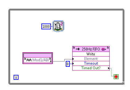
At the end of compilation, the error occurs if and only if I use a block of i/o node FPGA. This picture shows my very simple VI which fails to a compilation:
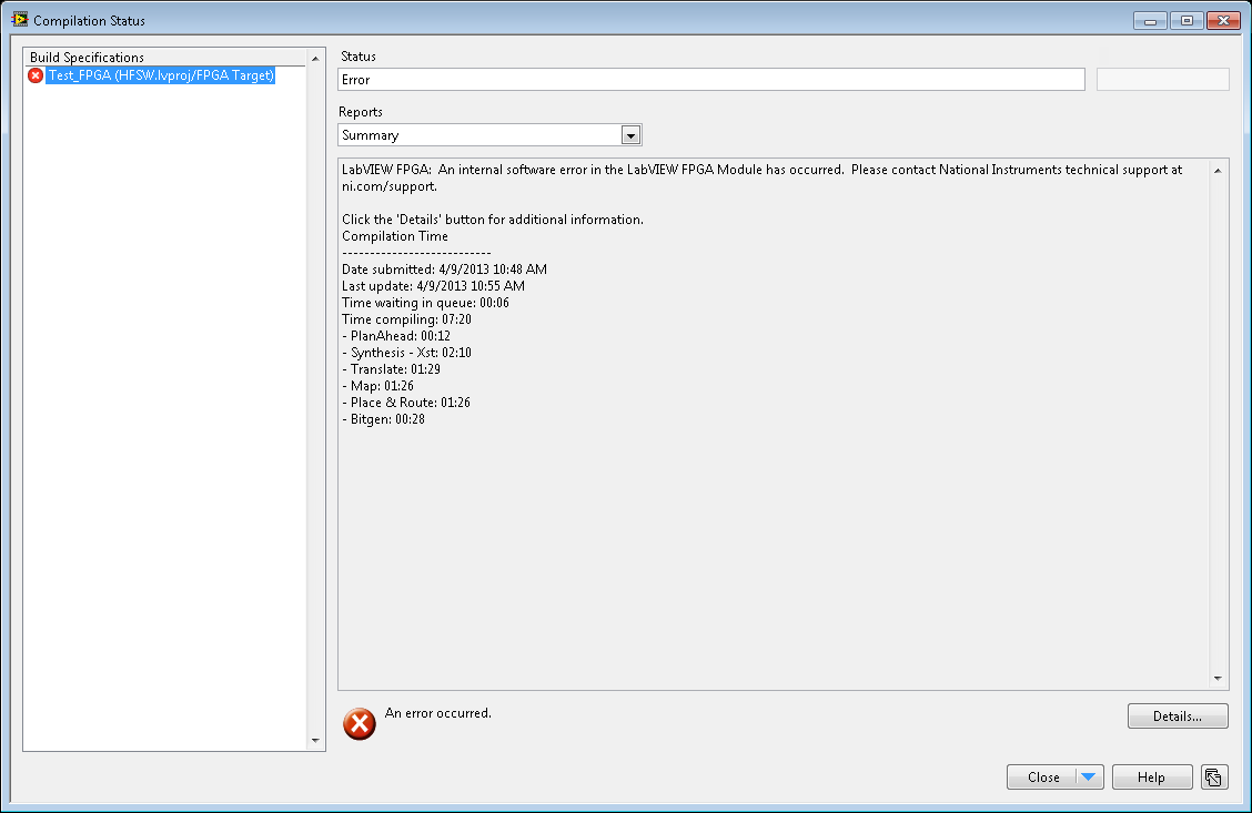
When I compile, I get this error at the end:
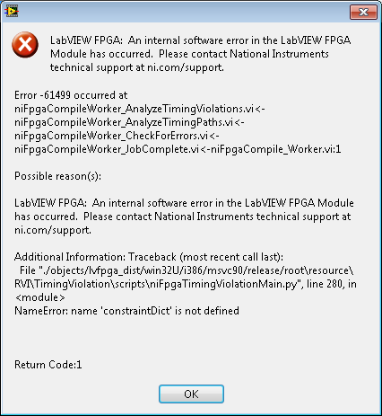
And here are the details of the error:
It is also interesting to note that the 'Timing' summary says I need a clock of 80 MHz, when the on-board clock of 40 MHz.
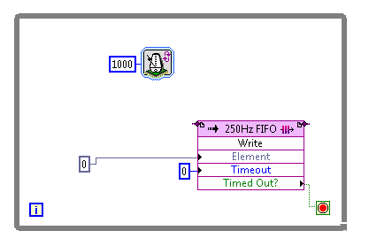
For comparison, when I remove the FPGA of e/s node and replace it with a constant, the compilation succeeds:
The need of a clock of 80 MHz disappears also, according to the report of timing.
Is this a problem with how loops work in FPGA? I've been reading about "single-cycle timed loops" that guarantee a performance per clock cycle. I don't have that kind of acquisition rate, and I guess the structure of loop, I created is not related to a single cycle because of the block of metronome, that I inserted. I guess correctly? Are there structures of loop for FPGA which is not related to a single clock cycle?
I also wonder if this error is not to do with my code, but is rather an internal error of the software compilation NOR, in particular the 'niFpgaTimingViolation.py' script mentioned in the summary of the detailed errors. I got labview 2011 and xlinx 12 installed on this computer before, but they uninstalled before the upgrade. This is my first project in 2012.
I appreciate the comments of the community NOR. Let me know if my question needs further clarification.
-Andrew
I solved the problem.
In case that someone looking for it later (error 61499 niFpgaTimingViolationMain.py that constraintdict is not defined).
I did a complete uninstall and reinstall my entire LV 2012 dev suite. Then the same VI used to compile failure began to pass compilation. Apparently, I had a corrupt file somewhere.
-
Hello
I would like to create a FPGA loop that runs at a fixed rate. Whatever if I use a timed loop structure or a timer loop express VI into a regular while loop? Under what circumstances should I choose one over the other?
I understand that the timer loop approach can cause the code in the loop run twice before calendar is established (but this isn't a problem for me here). Are there other differences in the two approaches?
Thanks in advance.
JKSH wrote:
But my question was about the differences between the use of "multi-cycle" Timed loops and VI express loop timer.
In a targeted FPGA VI, all call loops are single cycle timed loops (SCTL). This means that all the code in a SCTL must run in a clock cycle, so there are a few types of nodes cannot be used in such a loop. In a used while loop with a timer, you can use a wider range of features, but the loop will generally run much more slowly.
These documents may be useful to learn how to use loops clocked on FPGA:
Using loops of Cycle time unique to optimize the FPGA VIs
Optimization of your screws of LabVIEW FPGA: running in parallel and Pipelining
-
Sequence structure flat inside the timed loop and execution order
I have some problems trying to implement a flat sequence structure when you use a loop timed on a target of cRio VI
I tried with or without the while loop around the structure of sequence flat, and I also tried to replace the 'Non-deterministic loop' with a timed loop
The problem is that the program seems to run only once, then get stuck somewhere
I am writing a program that performs the following operations as soon as possible:
1. read the Pos_MC of entry on the FPGA
2 send the value of Pos_MC to the VI target (on cRio CPU)
3. calculate a value of output based on Pos_MC with a PID block ("exit PID')
4. send 'PID output' to the FPGA
5 write "PID output" analog output "MOOG".In addition, I want the program to return the measured value "Pos_MC" to a host VI for the recording of data
So that the output of PID is calculated and sent to the FPGA as quickly as possible, I placed a flat sequence structure to ensure that it happens before you send the output to the nondeterministic loop for recording data
Also, I want the digital input 'Stop' to be able to stop the loop deterministic (the timed loop)
I read much more entries than that and the help of several PID and exit, but I rewrote the code for a single entry and exit to make it easier to illustrate
Screenshot of the code is shown in 'target code.png' and 'fpga code.png.
The VI themselves are attached in the next post (cannot attach files of more than 3)
Question 1:
Any advice on how to get this race? Thank you!Question 2:
Is also my correct understanding in that, using this structure, each 0.9ms (fpga loop time) comes the following:
1. the input ("Pos_MOOG") is read on the fpga
2. the production of PID is calculated on the cRio with some delay to computation (for example 0.1ms)
3. the output of PID is then written for analog output "MOOG" in all about 0, 1 - 0.2ms
4. the FPGA program then waits until 0.9ms spent and repeat the processAs opposed to the next pass whenever performing a loop is started on the FPGA:
1. the FPGA reads the input and written on the output (the output of the execution of the previous loop PID)
2. then the entry is sent the cRio, PID output is calculated and sent to the FPGA
3. the new release of PID is maintained until the next time through the loop
Thank you!
PHG wrote:
Thanks for the input guys, any advice as to how I could get the feature in scenario 1?
I still say that the best route is just putting all the logic of the control in the FPGA.
Other alternatives include 1) the use of DMA FIFO sedn data back or 2) use interruptions so that the FPGA code can not read the output level until the RT.
DMA FIFOs are usually very limited, and I would not use them in this situation since I belive said it this code to do for the many outputs.
-
FPGA 2012 training: exercise fails '4-Wire Protocol' 7-2: not supported in single-cycle Timed loop
I work through the training courses OR 2012-FPGA with Labview 2014 SP1. I find the solution provided to exercise 7-2 called '4 son Protocol.lvproj' does not work. He is unable to run with the message "LabVIEW FPGA has reported the following error: item (s) not supported in single-cycle timed loop.»
Should it? I thought that the examples in the solutions folder were supposed to work such as provided. What needs to be fixed for this work? Thanks for any help.
Hello jbeale1,
It is a known problem. Here is the comment of NEITHER:
---------------
Exercise no. 7-2: 4 - Wire Protocol [Allen Hsu 2013.8.19]
- Description of the problem: exercise 7-2 uses a sine wave generator inside a SCTL VI. In 2012, LV, this VI is not supported in the SCTL, but LV 2012 will allow you to use mode 'simulation' (run on the dev machine). However, LabVIEW 2013 not even lets you use this VI in "simulation" mode If you run the VI with the sinusoidal generator inside a SCTL VI, LabVIEW 2013 gives you a "or objects not supported in single-cycle timed loop.
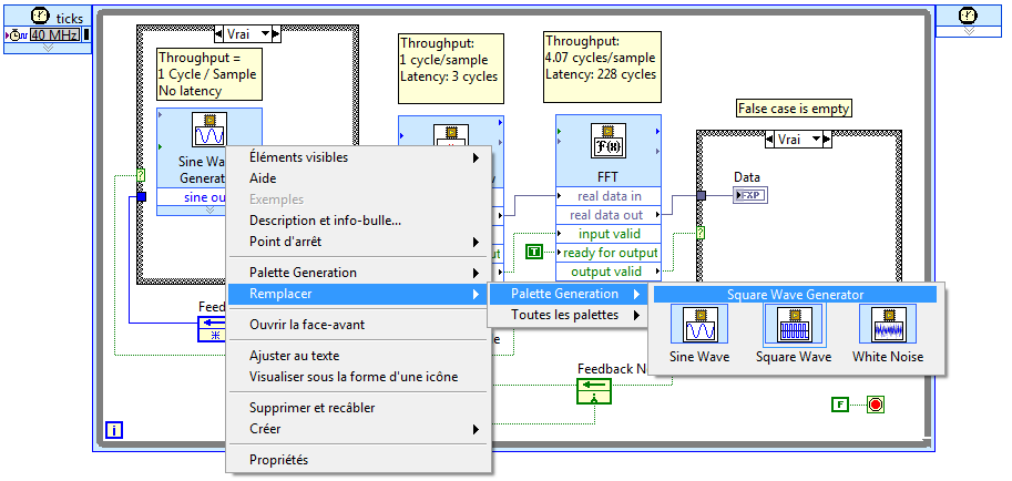
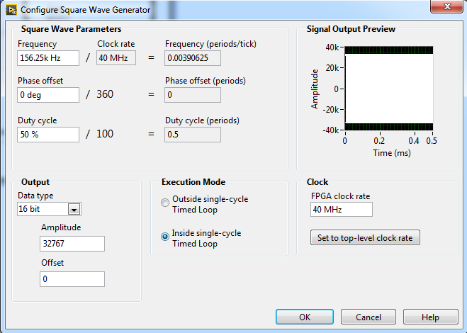
- Solution: If the students use LabVIEW 2013, you must tell the students to replace the sinusoidal generator inside the SCTL pre-built exercise VI VI with a Square Wave generator VI with the option "inside the SCTL" enabled in its configuration window, as shown below:
--------------
To replace the "sine wave generator" right-click on it and select the 'Square Wave Generator'. Then you have to double click on the "Square Wave Generator" and select "inside the only cycle timed Loop". You should then be able to run the example.
-
Operating system: Windows XP
Hardware: PCI 6259
Terminals used: PFI0 and PFI2
Counters used: Ctr0 and Ctr1
IM developing an application for the acquisition of data where timed loop synchronization source comes from my PFI2 (using the string A of an encoder). IM basically trying to acquire data based on the number of ticks from my encoder. For the synchronization source, I use counter 1 to capture the rising edge and have the loop time-acquisition of data. At the same time, Im using the counter 0 to count the number of rising edges so I know exactly in what tick data was acquired. PFI0 and PFI2 are connect to channel A of the encoder.
Questions:
Timed loop acquires data at each tick, because when I discover the data (text) file is missing count of my encoder value. Is it because there is a limitation on the Windows operating system? I used a noculars to measure the frequency at the maximum rotation of the channel encoder and 6,757 kHz. All solutions?
Also, is there anyway I can route the source channel internally an encoder to generate synchronization source instead of using another counter? I have attached my VI.
Hello
All the samples that you acquire will be read by LabVIEW in a sequential manner. Figure 4-21 on the M-series on page 80 (4-34) shows that you will acquire all the samples you request all channels that you enjoy in sequentially.
-
passing the value and to timed loop
Hello everyone,
I'm working on a VI that consists of a timed loop which takes values in a file every 6 ms and writes it to an output file. Inside this timed loop, there is also a MATLAB block that calculates a parameter based on the value. based on this parameter, that a marker is set to 0 or 1 (planned) to operate as a Boolean marker.
The problem arises when the marker is set to 1. I need an additional structure any that waits five seconds (without stopping the timed loop iterations) and a 'stop' button is not pressed an additional string is placed in the output file. I wish for the marker to get back to 0 if you press the 'stop' button and not string to put in the file.
The main problem seems to be the use of a structure outside the timed loop. I can't have a while loop or any structure that waits 5 seconds inside the timed loop. And if I let him out he does not have the value of the marker second structure during execution of the timed loop.
+ Any ideas on what the structure to be used during the 5 seconds Timeout? (I tried a while loop)
+ Use a local or global variable for the marker? (I tried briefly, but as a local variable, I couldn't choose a variable defined in the MATLAB block, and I don't understand global variables in LabVIEW)I enclose a simplified version of the VI as well as a sample input file in case it can help visualize.
Thank you
DAVASo far, there are a few problems with your solution, but first of all, I will try to help answer your original question.
You are right that you can't have a structure inside the timed loop which waits five seconds without blocking execution of the timed for the same period. You are also right that you cannot simply communicate through cables to an external structure. If you exit a loop of wire in the other, which creates a dependency of data flow, which means that the data loop cannot run at all until another loop ends its execution entirely and send data.
You have two options:
- Don't actually use a wait function to determine if the 5 seconds elapsed. Use the Express VI of time elapsed (search the palette). He just guard track of how much time has passed since the last reset. It does not wait. If you are safe to use inside your loop timed in a case that is triggered when the marker value becomes 1. Also check the Boolean command in this case Structure to decide if you should output the data in the file.
- Use an outer loop as in the example you posted, but use screws of the range of synchronization to send data between the parallel loop. Consider a queue.
But overall, I don't think there is much chance of this work very well. No way, the Matlab Script node running fast enough to run at a time of 6ms. Also no way it works in a deterministic way at all. He needs to communicate with an external program, so its execution time is really unlimited.
-
FPGA square wave generator diverts loop calendar
Description of the problem:
I have a simple while loop with a structure of matter inside. In one case, I have the
Generator FPGA Sinewave sending the data of output to AO0, otherwise, I have
the square wave FPGA sending output to AO0 generator. The sine and square
waves are set to run at 10 kHzI also have a shift register that changes the State of DIO0 each loop through.
In this way, I can look DIO0 on my scope and say how fast the loop runs.When I choose the sine wave generator, the output on AO0 is what I expect. That
is I have a sinusoidal signal at 10 kHz and the loop speed is approximately 1 US. Everything is good.Then I move to the square wave. I get a signal square 10 kHz, which is good. But
My loop speed was slowed down to 50 US (it follows the square wave
exactly) is: once the loop defines the FS square wave and the
the next time through the loop, it defines the square wave to-FS.My problem is that when I generate a square wave, I expect the speed of loop
to stay fast he does it for the sine wave. You can see what my loop speed
slows to 50 (a square wave of 10 kHz) and then all my calculations that must
go in parallel with the square wave will also be slowed.Please help me with my understanding of the use of the square wave FPGA sub - VI
Thank you
RichSoftware of NEITHER: LabVIEW FPGA Module version 2013 SP1
OR hardware: USB-7855R R Series deviceIf you dig into the express VI, it will loop an SSTL until there is a change in value. The sine wave has no need to do so because the value changes constantly.
If you can, I recommend doing your loop a SSTL and configure the express screw accordingly. This will work as long as the rest of your code in the loop can be run in a single clock cycle.
-
OR 9403: Digital Input/Output slows timed loop?
Hi all
I use a loop timed sample of 7 current channels (NI 9023), 3-channel (NI 9025) voltage at 1000 Hz in scan mode and it works fine. However, when I add for 8 output channels of the input/output module digital module NI 9403 for timed loop, CAPAS sampling cannot exceed 1000 Hz. According with time stamp data I wroten in file, it seems that I have in all ten milliseconds, I missed a miliseconds.
I would like to ask is there a reason for this? The digital I/o module affect the timed loop?
Thank you much in advance.
I'm not familiar with the FPGA code, so I can't comment there. However, I noticed that you call writing to text file twice in the timed loop. Can you only collect data and then write the files after the time loop? This would save a lot of time. For each entry, the program needs to access the hard disk, find the end of the file, add him and return to write on the hard drive. A lot of your time, especially since the files are getting bigger.
-
Programming a module FlexRIO FPGA to computer?
Hello
I'm new to National Instruments LabVIEW equipment. I have a FPGA FlexRIO SMU-7965R module and a RF Transceiver 5791.
To use this equipment, do I have to have a chassis (to put my FPGA), or can I simply program the FPGA on my computer (using a cable)?
João
Hi João,.
You should always at least a SMU chassis with a controller. The SMU-7965R Board is like a PCIe card only a different form factor. You must put it in a slot SMU as you need to put a PCIe card in a PCIe location.
I suggest trying the PXI Advisor to see what type of systems, you can use. PXI Advisor
Choose your Board under Modules, then only supported chassis and controllers will be available.
When you choose to create a LabVIEW project with the jury FlexRIO (FPGA target) in my computer, you specify that you will use the FPGA target with a Windows host.
Here's an introduction to LabVIEW FPGA Webcast:
http://www.NI.com/Webcast/240/en/
Best regards
Klas Andersson
National Instruments
Support
-
Using of FPGA VHDL IP and analog output
I use a system with Labview 2014 PXI. I've got Labview FPGA to program and run the card PXI-7854R.
I have the VHDL Code I want to use to control an analog output of the card. I use the IP integration node for this now but I also tried it making the process CLIP and still have not been successful. The problem that arises is that the IP integration node must be in a timed loop, while the analog output indicates that it cannot be put in a timed loop. Is there a way to provide an output of VHDL analog outputs of the card?
I tried to embed a loop timed within a while loop, but it still does not work.
I can't download the VI due to the policy of the company, but suppose I'm generating a sine wave in my VHDL code which must lead to the analog output of the card (the actual wave is company owner information but it is generated by a glance to the top of the table as a sine wave VHDL would be).
In an attempt to work the problem I retried import CLIP of the HDL code in a new project in Labview and VI. I'm still not sure about why it did not work with each other when I tried it.
For anyone who seeks to solve this problem:
I basically used this tutorial for the process CLIP: http://www.ni.com/tutorial/7444/en/
It also explains the differences between the CLAMP and the IP integration node.
-
I have two codes for my NI9024 cRIO; an FPGA and a side side of RT.
In my RT code, I use a frequency of 1 MHz for my timed loop.
Just wanted to check if I should consider certain things important when using this frequency or not.
I mean, is there a particular point or referring to the fact that I had noticed.
Is there any limitation, future problem or question?
Just to be careful.
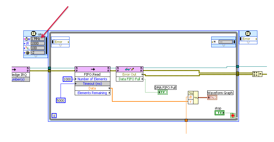
I think that the point that you are missing, it is that it is never necessary to update a graph 1000 times per second! operators just can't see that fast! So, unless you save the data on a disk, you can use a much slower pace of update. You can indeed, be limitation in this loop timed by your actual acquisition rate (timeout is 5 seconds - what is the sampling frequency of the FIFO?)
If the buffer is full or reduce the sampling frequency of the FPGA (a million points per second is really much more that a human eye can process) or increase the number of samples by reading.
Maybe you are looking for
-
Where can I find the themes I downloaded. They are not in the page more modules.
They aren't in the appearance tab more as they were before. How can I change my themes now.
-
report of Crash response: RtlEnterCriticalSection, what do I do now?
I can't use Firefox at all. From the desktop, I click on the firefox icon and receive notification of the accident. I went to the Firefox support and using editing there was another brouser got the signature of the accident, it is: RtlEnterCriticalSe
-
The event log does not start error 31: a device attached to the system is not functioning
I can't get the service to start on my winxp sp3 pc event log. I have tried everything I know: Running sfc/scannow Reset permissions Search for malware and viruses Rebuild the WMI Create a new account Nothing seems to work, I think that this is relat
-
Impossible to use the system in sleep or Hibernate mode after installing a new video card
Have a card GeForce 6200 graphics with latest drivers installed and now I can't use the features of standby or Hibernate mode in Windows Xp System.
-
Advantage of ink HP deskjet 1515: why does my printer print fonts that are so small even read?
So I bought this printer about 3 months ago and everything went smoothly... But last night when I tried to print a slide power point, it prints all of a sudden the texts which are so small... In fact I put it for 4 days by sheet until I print it, but