Parallel FPGA in LabVIEW/Multisim co-simulation
Hi guys, it is possible to put 3 or 4 FPGA modules in a model of LabVIEW and then simulate jointly with Multisim runs 1 model plant? I want to simulate a converter of solar by using multiple parallel FPGA (this part on LabVIEW) cores conducted multiple interacting with the grid inverter bridges (this part is the Multisim factory model).
Hey hacmachdien,
This should be possible. If you have the Control Design and Simulation toolkit, you can use the control and the Simulation loop to simulate jointly with Multisim after you have installed the co-simulation plugin that comes with Multisim. See here for more information.
If you encapsulate your LabVIEW FPGA logic inside a Subvi, you should be able to use these subVIs in control and the loop simulation. There are a few caveats with this. First of all, the rate for the LabVIEW FPGA SubVIs must be configured depending on how they will run in the actual hardware. For example if the Subvi is inside a timed Cycle simple loop that is configured for a 40 MHz clock, you will need to configure the delay for the Subvi 25 ns. You can set up the period right-click on a Subvi in control and Simulation loop, then go to the Subvi node installation. In this menu, you can set the type of operation to be discreet and then configure the discreet calendar. Another restriction is certain things will not be supported as I/O. You can usually work around this by leaving your IO on the next level of your app and just by passing the values in the Subvi through controls and indicators. Let us know if you have any other questions!
Tags: NI Software
Similar Questions
-
Multisim co-simulation / LabVIEW
Is it possible to add contacts from two States to Multisim and control of Boolean way to LabVIEW?
the attached example schema
-
Complete equipment of simulation using LabView, Multisim, and MAX (easy answer accepted!)
Hello, all!
Sorry, I'm new, but I checked around for a definitive answer on this, but I'm not 100% sure. I learn LabView for a physics of upper-division course. We use hardware (DAQ - MX) and a mixture of laboratory equipment - mainly stuff such as voltmeters, oscilloscopes and test setup with simple components. I also work with NIM instrumentation, but that's secondary to my needs here. So, when I'm away from the school, is it possible to make a complete simulation of my classroom work using LabView, Multisim (for my model) and the measurement and Automation Explorer (for the acquisition of data-MX)? I know I can create a circuit and drop it in Labview, but I'm not sure on the acquisition of data. I hope for what is a "seamless" reconstruction of what I do in class. I can't take a simple 'yes' or ""; as long as I know it's possible, I can find the solution.
Thanks for the help!
I wrote 'sim' screws in many situations where I need to work away from the hardware store. I think that MAX has a few features, but you may be limited in the types of signals, you can simulate.
For my sim screw, I make a copy of the original VI with ".sim" added file name. I also change the icon in a characteristic way to identify the version of the sim card on the BD. In this way the two VI have the same connector pane and are interchangeable on the BD structure. disable the diagram can be your friend here. Inside of the VI of sim, I generate the signal in any form I want. You can also add additional if necessary controls.
Lynn
-
What are the differences between LabVIEW and LabVIEW FPGA and LabVIEW RT
I need a comparison of LabVIEW, LabVIEW FPGA, and LabVIEW RT
Sorry, I misunderstood.
LabVIEW RT (LabVIEW Real-time) combines graphical LabVIEW of programming with the power of a real-time operating system, allowing you to create applications in real time.
-
I would like to write to a data generator circuit connected to a parallel port.
Is there a driver for parallel port in labview on windows xp?
Examples see LabVIEW 5 only if you are using LabVIEW version 5.
If you are really using LabVIEW 8.2, you should have the example called Parallel Port and loop to write. There is nothing in this VI which refers to older versions of LabVIEW and the only restriction is that he cannot run on Vista.
-
Software FPGA with LabVIEW 2013
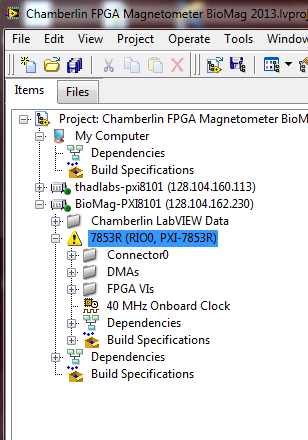
I have a system with a rotating computer "development" under Windows 7 and an NI PXI-1036 chassis with a PXI-8101 controller as well as a card FPGA PXI-7853R. Recently, I upgraded to LabVIEW 2011-2013 of LabVIEW. I kept LabVIEW 2011 installed just to make sure everything is still working on the new LabVIEW.
Now, when I open my project in LabVIEW 2013 Project Explorer, my FPGA comes with a warning triangle yellow next to him (see attached photo). The warning says:
"Software support for this target FPGA is not installed on the computer. You can view and copy elements into the project, but you can not compile any screw under the FPGA target, until you install support for the target. Refer to the documentation of specific material for more information on the proper drivers and for more information about the installation and configuration of the target FPGA ".
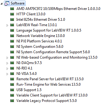
Regarding the installed software, I have LabVIEW SP1 of 2013, 2013 of LabVIEW FPGA Module SP1, SP1 of Module 2013 LabVIEW Real-time, and Xilinx Compilation tools 14.4. On the chassis of the TARGET (with the PXI-8101 controller), I have attached a list of installed software.
Interestingly, when I open the project in LabView 2011, no errors or warnings are present with the FPGA card. It is only under LabVIEW 2013 I see the warning. Did anyone see a glaring omission of software that could be the cause of LabVIEW raise this error? Thank you for your help.
Best guess is that're missing you the driver for your FPGA device. Try to install the latest version of NOR-RIO (or at least the version supplied on your 2013 SP1 install disks). Have you installed device drivers at the time that you have installed SP1 2013 LabVIEW?
-
A UDP connection target FPGA with LabVIEW
Hello
I have an FPGA with Ethernet connected to my HOST PC, now I would like to connect the LabVIEW FPGA target and access to its records. Please suggest me.
Kind regards
Chetan
Hi Cheetah,.
don't know, because I do not know your format or the manual of your FPGA...
-
Hardware implementation of the controller DMA using the FPGA and LABVIEW
Respected Sir/Madam
I am simulating the DMA using LABVIEW7.1 controller and I am fresher to this tool, please suggest me how to do this
You can go through the FPGA tutorial.
For specific information on DMA you can see this.
-
I installed 32-bit and 64-bit LabVIEW 2012 SP1 on Windows 7 X 64 computer. After that, I installed SP1 FPGA Module. While module FPGA completely installed in the 32-bit version and could develop projects fpga, FPGA interface has not installed the 64-bit version. Anyone had this before question?
The document 5WMF8NQ2 knowledge base says it's doable.
I have tried to repair the installed module, remove and then reinstall the module. Nothing helped me to get the FPGA interface on a 64-bit host VI. Any suggestions? Addition of the individual screws through the range of editing functions like a tedious process and the palette is not completely functional.
I solved the problem. Had to repair each driver separately for LabVIEW 2012 SP1 64 bit installed on the default drive. You may need to copy paste files to the folder that it installed in function.
-
Hello
I m using a module NI 9870 in my Crio system and the program worked fine.
The problem I have is that I also need to use a Profinet PN module, and when I try to use both programs included in my FPGA, my 9870 module does not work like it s supposed to (it s points--instead of the characters).
Can someone help me with this? is it assumed that the different loops are independent and without any problem, are - it true?
or do I have to implement a program in a different way?I would appreciate any idea or entry,
Thanks a lot for your help!
Thanks to all for the replies.
I ve already solved the problem, and it was the size of the FIFO for reading.I use only a FIFO for reading, and to do this, I included a number after the data, according to which I m from port to aid. When the size of the data in the FIFO is not exactly the same that in the FPGA program, this function does not work correctly and returns false data.
After this change, the program worked correctly.
Thanks in any case again for your time! -
Hello
I have to import the VHDL code in Labview. I would like to know what the best solution what CLIP, integration IP node or node on HDL from the previous version of Labview if it is possible to use it.
Thank you
Hello
I think that these documents will help you to choose from, depending on your needs:
Difference between nodes CLIP and HDL
CLIP and the differences of node IP integration
Kind regards
-
Someone at - it Temp vi for LabView 8.5 Simulator?
Everything has a temperature for LV 8.5 Simulator? I am in desperate need!
Michael B
What do you most need of a random number generator? Have you tried doing a search for temperature in the finder of the example? You will find two less - "Simple Temp Datalogger.vi" and "Temperature.vi graphic.
-
How to synchronize parallel VIs in labview 7.1
Hello
I want to synchronize two parallel screws. If someone knows what you can help me.
Aisha
-
I'm using LabVIEW-Multisim co-simulation for ordering a buck converter circuit. When I run the VI which controls the converter circuit in Multisim, I get an error code-2367. Specifically, its this error:
External model buckconv.vi/Control & Simulation loop
doAnalyses: Timestep too small(M202)
I think that the error is the framework of simulation in Multisim, but I do not know what parameters to change so that I can solve the problem.
Hello
Normally for a problem of scaling of the timestep I would adjust the tolerance values. In your loop control of Simulation, if you pull the bar to the left, there are 2 options for tolerance (relative and absolute). Try decreasing the accuracy of these (instead of e-12, e-08 of use). Also the minimum and maximum values of stepsize control are there as well if you can try chaning those. Let me know if it works.
Best regards
-
by using labview co-simulation, how to control the PWM market factor in multisim
I am new to the use of Multisim with LabVIEW using co-simulation. I would like to ask if there is a PWM component in Multisim, which can have its cycle have to be controlled using LabVIEW? I have an algorithm in LabVIEW that returns the duty cycle values between 0 and 1, representing the percentage of duty cycle.
How can I control the PWM market factor in Multisim using LabVIEW co-simulation?
Thank you very much
SPECTRUM
Hi spectrum,
In Multisim, find items based on functionality, there are some PWM models in the database. Take a look at this knowledge base if you don't know how to search for parts:
http://digital.NI.com/public.nsf/allkb/7309A5CABC677296862577ED006EC99E
Also, take a look at this knowledge base:
http://digital.NI.com/public.nsf/allkb/EF391C48CF71AE4F862571B900644F84
This article shows you how you can get Mutlisim and LabVIEW to co-simiualte:
http://www.NI.com/white-paper/13663/en
I hope this helps
Maybe you are looking for
-
Is there a way to route with maps of Apple?
I need to plan a multi leg travel. I can do in Apple Maps? If this isn't the case, someone has a suggestion for a site or app that does this that has a 75% or higher customer reviews?
-
Somehow ended up getting the beta - I just want full releases. How can I change this?
I guess I asked to ot in the beta...? I don't want to get betas, only full versions. can not know what to do. Help? Thank you...
-
How to uninstall all firewalled and set up a new
How safley uninstall a firewall and set up a new one?
-
Windows 8 app names (Plaid) are not in my language
Hello I had this problem where all my built-in apps (weather, news, people, etc.) were in English. Following the advice that I found here, I changed my primary language in French and it worked partially: the contents of built-in apps are now in Frenc
-
Master Page Items question: I use master pages for a 60 page document and just found out that some of my master page items are multiplying! There are some boundaries on the pages, and some of them are constantly a quantity apparently without end on t