myRIO differential LVDS signaling
The myRIO can be configured to read or write songs by LVDS signaling?
Hi hkhalili,
The myRIO-1900 and myRIO-1950 only have single-ended DIO. Currently, if you have need of LVDS signaling and have a background in hardware design, the sbRIO-9651 has two LVDS input and output capacity. The sbRIO-9651 is a system on Module (SOM) and requires the development of a carrier Board of things like supplying electricity but also out the requested OID for your request.
The sbRIO-9651 is definitely a notch above in the flexibility and the configuratbility of a product of RIO, but it also comes with a learning curve and more steep development.
Tags: NI Products
Similar Questions
-
How to measure differential analog signals
I read the hand signals and measure single-ended and differential, but I still don't know if a method is appropriate for my applications. Basically, I connect a BNC to one of the analog channels. The NLC has the real signal in a single thread (internal male) and land in the other thread (external shielding). I connect different components to different analog inputs so that they cannot share the same field (or the negative terminal). What is the best way to acquire this kind of data. It seems incremental settings on Panel (BNC-2090) different records between, say, ai1 and ai9. I don't want that because I want to record the difference between the two wires that are connected to the ai1.
Who said that a differential signal is connected to two different BNC? You need to look at the manual? The diagram in figure 2-2 is quite clear on the connections on the way in which the shield is connected in differential mode.
-
SMU-7975R with FPGA Kintex-7 - LVDS problem
Hello
I developed a custom RIO FLEX module (Digitizer18, 0xAB66 - vendor id) and try to use it with the card 7975R-SMU-FPGAS (FPGA Kintex-7)
I have a problem, try output LVDS signal via aUserGpio (61) and aUserGpio_n (61).
These pins are not K7 capable clock, but I used this module FLEX RIO with SMU-7962R (Virtex-5 FPGA) where these pins are capable REGIONAL clock and it worked fine.
Kintex-7 it compiles without error, but I see no signals on the pins aUserGpio (61) and aUserGpio_n (61), although its switching State is ADC2_FSM.
Is it possible to use pins that is not capable of WHAT LVDS output or I am condemned to use MRCC clock or pins SRCC?
Thank you
My xdc file (aUserGpio (61) and aUserGpio_n (61) belong to the 18 Bank):
set_property IOSTANDARD LVDS_25 [get_ports {aUserGpio [61]}]
set_property FAKE DIFF_TERM [get_ports {aUserGpio [61]}]
set_property IOSTANDARD LVDS_25 [get_ports {aUserGpio_n [61]}]
set_property FAKE DIFF_TERM [get_ports {aUserGpio_n [61]}]# all unused pins Bank 18 are LVCMOS25
set_property IOSTANDARD LVCMOS25 [get_ports {aUserGpio [49]}]
set_property BUNCH SLOW [get_ports {aUserGpio [49]}]
set_property DRIVE 8 [get_ports {aUserGpio [49]}]
set_property BIO FAKE [get_ports {aUserGpio [49]}]...
part of my clip to vhd file (because it's too big and all other LVTTL logic works very well except LVDS):
attribute dont_touch: string;
Signal ADC2_CNV_buf: std_logic_vector: = '1';
attribute dont_touch of the ADC2_CNV_buf: signal is 'true '.OBUFDS_ADC2_CNV: OBUFDS
map of port)
O-Online aUserGpio (61)-Diff_p output (connect directly to the port of higher level)
OB-online aUserGpio_n (61)-Diff_n output (connect directly to the port of higher level)
I have-online ADC2_CNV_buf - the input stream
);....
process (LVDS_CLK) - 200 MHz
Start
If LVDS_CLK' event and LVDS_CLK = "1" then
ADC2_FSM case is
When s0 =>
If ADC2_CNV = "0" then
ADC2_timer1 <= (others="">' 0');
ADC2_timer2 <= (others="">' 0');
ADC2_CLK<=>
ADC2_READY<=>
ADC2_CNV_buf<= '1'="">
ADC2_FSM<=>
end if;
When s1 =>
If ADC2_CNV = "1" then
ADC2_CNV_buf<= '0'="" ; ="" ="" ="" ="" ="" ="" ="">
ADC2_RESET<= '1'; ="" ="" ="" ="" ="" ="" ="" ="" ="">
ADC2_FSM<=>
end if;
When s2 => ADC2_FSM<=>
When s3 => ADC2_FSM<=>
When s4 => ADC2_FSM<=>
When-online s5
ADC2_CNV_buf<= '1'="" ; ="">
ADC2_RESET<=>
ADC2_FSM<= s6;="" ="">
When-online s6
If ADC2_timer1< x"28"="" then="" --="">
ADC2_timer1<= adc2_timer1="" +="" 1;="">
on the other
ADC2_FSM<=>
end if;
When s7 =>
ADC2_CLK<= not="">
If ADC2_timer2< x"24"="">
ADC2_timer2<= adc2_timer2="" +="">
on the other
ADC2_READY<=>
ADC2_FSM<= s0; ="" ="">
end if;
When other => ADC2_FSM<= s0; ="">
end case;
end if;
complete the process;-the host uses the flank amount of DCO± to capture D±
process (UserGClk2, ADC1_RESET) - echo DCO2 clock
Start
If ADC1_RESET = "1" then
ADC2_READ_FSM<= s0; ="">
ADC2_BUF <= (others="">' 0');
elsif UserGClk2' event and UserGClk2 = '0' then - host uses the flank amount of DCO± to capture D±
ADC2_READ_FSM case is
When s0 => ADC2_BUF (17)<= not="" d2="" ;="" adc2_read_fsm=""><=>
When s1 => ADC2_BUF (16)<= not="" d2="" ;="" adc2_read_fsm=""><=>
When s2 => ADC2_BUF (15)<= not="" d2="" ;="" adc2_read_fsm=""><=>
When s3 => ADC2_BUF (14)<= not="" d2="" ;="" adc2_read_fsm=""><=>
When s4 => ADC2_BUF (13)<= not="" d2="" ;="" adc2_read_fsm=""><=>
When s5 => ADC2_BUF (12)<= not="" d2="" ;="" adc2_read_fsm=""><=>
When s6 => ADC2_BUF (11)<= not="" d2="" ;="" adc2_read_fsm=""><=>
When s7 => ADC2_BUF (10)<= not="" d2="" ;="" adc2_read_fsm=""><=>
When s8 => ADC2_BUF (9)<= not="" d2="" ;="" adc2_read_fsm=""><=>
When the s9 => ADC2_BUF (8)<= not="" d2="" ;="" adc2_read_fsm=""><=>
When s10 => ADC2_BUF (7)<= not="" d2="" ;="" adc2_read_fsm=""><=>
When s11 => ADC2_BUF (6)<= not="" d2="" ;="" adc2_read_fsm=""><=>
When s12 => ADC2_BUF (5)<= not="" d2="" ;="" adc2_read_fsm=""><=>
When s13 => ADC2_BUF (4)<= not="" d2="" ;="" adc2_read_fsm=""><=>
When s14 => ADC2_BUF (3)<= not="" d2="" ;="" adc2_read_fsm=""><=>
When s15 => ADC2_BUF (2)<= not="" d2="" ;="" adc2_read_fsm=""><=>
When s16 => ADC2_BUF (1)<= not="" d2="" ;="" adc2_read_fsm=""><=>
When s17 => ADC2_BUF (0)<= not="" d2="" ;="" adc2_read_fsm=""><=>
When s18 => ADC2_READ_FSM<=>
When other => ADC2_READ_FSM<= s0; ="">
end case;
end if;
complete the process;
ADC2_DATA<= "00000000000000"="" &="" adc2_buf="">I've made a few changes to TestCLIP.fam:
...
[FlexRIO-K7IOModule]
DefaultCLIP = TestCLIP
VccoLevel = 2.5...
And my xdc file now looks like this:
# Set the voltage from Bank to Bank 18.
#set_property IOSTANDARD LVCMOS25 [get_ports-filter {IOBANK == 18}]set_property IOSTANDARD LVCMOS25 [get_ports {aUserGpio [*]}]
set_property IOSTANDARD LVCMOS25 [get_ports {aUserGpio_n [*]}]
set_property IOSTANDARD LVDS_25 [get_ports {aUserGpio [58]}]
set_property IOSTANDARD LVDS_25 [get_ports {aUserGpio_n [58]}]
set_property IOSTANDARD LVDS_25 [get_ports {aUserGpio [67]}]
set_property IOSTANDARD LVDS_25 [get_ports {aUserGpio_n [67]}]Now it's working.
-
How to run code and to communicate between the computer and myRIO?
Hello
I am trying to create a colortracker using the myRIO. The system is pan tilt servo with a webcam. The project works well and is able to follow and move with the desired color. However, in order to continue the project, I want to ensure the system with another device for the perception of depth and want to use the host computer for webcam and image processing and the myrio to get signals for the servos. The idea is to connect two webcams directly to the computer usb ports and keep the myRIO connected to everything does time i.e. no wifi. Can anyone guide me as to how I would go about sending signals constantly between the computer host and myRIO?
I advise to use Variables shared Network-Published or network stream.
You can read about them both in the cRIO guide Developer: http://www.ni.com/pdf/products/us/fullcriodevguide.pdf
There are also examples for both in the Finder for example LabVIEW.
-
Connecting two devices myrio single labview VI
Can a single labview VI tracks/controls two myrio peripheral at the same time? Or I should perform only a single device and do communicate wirelessly with each other?
If you collect signals at a place with a myRIO and send the signal to an another myRIO somewhere else, what myRIO use yo signals control two motors. I understand?
A simple solution is to have the myRIO signal collection write the signal to a shared variable, and have the myRIO control read the shared variable engine and the engine control. Two MyRIO will work asynchronously in this case. Are there special requirements for synchronization? Because it is quite difficult to more wireless sync.
-
frequency DAQ USB issue (6211)
Hello
I'm a newbie when it comes to NOR and data acquisition. I bought a NI USB 6211 and connected a resolver with 400 Hz and ai1, ai2 (CSR) (sine and cosine signals). I also have the reference of the power supply connected to ai3 (differential) of signals. Pockets of tension give a +/-2.5 Volts from all sources input signal.
The problem is that the signal moves to the right. She moves uniformly for all signals.
Now, I wonder is it possible to synchronize the input signal so that it moves? or what I need to resolve this issue programmatically? I'm programming in C with standard DAQmx drivers (v15.1). But I saw the same problem with Labview and Measurement Studio.
Thanks in advance for your suggestions.
Kind regards
Gerhard
I guess I just find the answer to my question here:
http://forums.NI.com/T5/LabVIEW/DAQ-Assistant-can-t-lock-the-signals/m-p/1332484#M542285
I guess I have to ask in the forum section of C++ for an example of a software lock.
Kind regards
Gerhard
-
Test the analog inputs in a PCI-6013
Hello. I m using a PCI-6013 OR DAQmx 9.1.1 with Labview 8.2 (sued) WinXP. The jury has undergone an immersion in water during a flood but was cleaned, recognized by WinXP and NIDAQmx.
I have run the Measurement & Automation explore and use the test under option OR-6013 'Dev1' panels 'devices and Interfaces. Here, I can see that the digital and clock output work perfectly (I can change the State of the digital channels and duty cycle and frequency of the clock). The problem arises when you try to measure an analog voltage. I tried on several cases not all analog channels using NRSE and differential modes (switch accordingly connections).
The signal comes from a (4 Hz, squares and sines, 5Vpp) signal generator via a CB-68LPR connector.
I only see something comparable to the entrance of singal when you use differential inputs (signal connected by J57 and J23) AI7, but the signal I see comes with 100 mVpp instead of 5 Vpp (I can see changes in the shape, every time that I have spend of a sine, square, ramp...). I also tried connecting J23 AISENSE (J62) and AIGND (J67), to avoid the problems of floating source. The same thing happens when enter and set up the acquisition by the vicinity of data in the Explorer of Measurement & Automation. I m using the reach of the signal in the different ranges, tried with 04:55, -1 to + 1, 09:50... When you configure tasks NIDAQmx I choose to read different samples (100, 1000, 10000) rate (100 Hz, 1 kHz,...) and combinations. Anyway, the input signal is always 4 Hz. I checked the signal with an osciloscope and I see it perfectly.
Is it possible to have the broken while the digital and general-purpose analog input clock outputs are OK? Y at - it a tip for the connections I should know about? Thanks in advance for any guidance!
Thank you both, KateB and MarisolM for your answers.
I made several the tests con señales DC y con señales senoidales, instalando placa en back different computers, y no obtengo resultados positivos, is spite of what el self-test selling well. Seems that the Plaça realmente esta fallando.
I did several tests with DC signals and senoidal, installing the card in two different computers, without positive results, even if the self-test is OK. It seems that the Council really works hard.
Are concentration cotización por su reparación. Gracias!
-
generation of two complementary pwm signals using myrio
Hello, im working on a project and I need to generate two complementary pwm signals (when we go to 1, the other goes to 0) using myrio.
the problem with the blocks of myrio pwm is that when you set the market factor, the signal always starts with its high value. Can someone help me please?
Hello
You can create a Boolean square signal with chosen service and frequency cycle, create its opposite with makes NO sense and then send both signals via Digital Out vi (myRIO/Default/Digital Out) to two different outputs.
Best regards
-
myRIO - measure unique output completed using differential input
Hi all
I had used myRIO 1900 to measure the power of the microphone, which varies from 0 to 5V (biased to 2, 5V).
I used one of the analog input ports completed only connector MXP or B to read the value.
A few reasons, I changed the microphone with amplifier and when measured using oscilloscope and other hardware DAQ, supply range of + 5V and - 5V.
As the MXP is unable to read the voltage-ve, I realized that I need to change the connection to the MSP connector C.
It is mentioned in the dataheet of myRIO we can measure up to differential Channels analog input +/-10 V.
Although there are some reference materials available, I do not understand completely how to read the single ended output using differential input.
Should I use no matter what op-amp or comes directly from their phone?
Can someone kindly explain to me the differences and some references on how to connect!
Although I tried to read through this white paper, I felt completely lost

http://www.NI.com/white-paper/3344/en/
Exit ended unique direct and/or the amplifier has 2 pins: GND and Vout
Entered different a 3-pin: A +, A - and ALWAYS
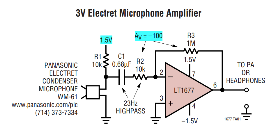
I had attached the screenshot of the form OP amp for your reference
I think that you just connect your Vout to the + ve differential termination, MASS to Terminal - ve. (Briefly) An asymmetric measure is between the channel of GOT it and STILL while a differential measurement is between the + ve and ve - terminal. One measurement unit completed is referenced to GND is where you are measuring the tension of.
-
MyRIO FPGA read framework signals SENT
Hello community,
I now have a myRIO with Labview 2013. I try to read a digital signal to a sensor on the port DIO0 (C-Port). It works very well. The problem is that I don't know how to find the start (the SYNC nibble) of the frame SENT - and how it works with the ticks of the clock / time clock of the FPGA (40 Mhz) system. I do not understand the meaning of the clock. ticks of the clock.
The next problem is to measure the time between a front down to falling edge. In fact I can detect every falling edge of the signal SENT but I cannot measure the actual time between them. How can I measure the real time based on the system FPGA clock time? The nibble of SYNCHRONIZATION were all 56 time graduations. But how long are 56 ticks?
Best regards
Basti
Hello, Alexander.
Thank you. It works very well.
Now my problems are solved. The main problem was to build something that is capable of converting 56 ticks of the SYNC signal SENT for correct ticks of the sampled signal. The two frequencies, the Signal SENT (333kHz) and the sampled signal (40 Mhz) are different, so I divided the frequency of the signal sampled frequency of the Signal SENT - (factor of about 120). Now I can convert 56 ticks to correct the number of ticks of the sampled signal and I can find the SYNC - Puls in FEEL. The result of 56 times the factor of 120 ticks is 6720 ticks. So, I convert ticks to the correct frequency.
Thank you very much for your help!
Best regards
Sebastian
-
NIDAQmxBase uses differential signals?
I recently updated the NIDAQmx Base to the plus version and. But now I'm a horrible corruption of my signals. I checked with a scope and the signals are correct, but it sounds horrible crosstalk between channels. The only thing I can think is that the Council does not truly differential switching beyond the first 8 channels.
I use a card of 64 channels so there are 32 differential channels, I'm only using 16 channels beginning. I use ' Dev1 / ai0:7, Dev1 / ai16:23 "for the specification of my channel. The equipment works as the default "Datalogger" shows the correct data. But I'm guessing that the data recorder was built with an earlier version of the basis of NIDAQmx. This seems to happen when you use more than the first 8 channels. This VI allows to work with the previous version of NIDAQmx base.
Is this a known issue?
Here's the code to initialize the jury NOR-6033

Mac OS X 10.4.11 PPC / LV 8.5.1 / NIDAQmx Base 3.2.0 / VISA 4.4.0
Hi Scott-
I agree that relocation is the most appropriate next step. I tried here with a very similar setup and I could get the correct number of samples during my reading, and accurate data looked. Please let us know your results once the reinstallation completed. Thank you-
Ed
-
create the differential signal of 6289
Is is possible to create a sine wave of differential on the output of the 6289? And how can I do this.
I created a differential DC 1V AO0 positive and negatives 1V AO1. Then measured on a differential input ADC signal, which is my DUT.
Now, I'm cutting the CMRR and wanr to use the DAQ6289 because I don't want to add another piece of equipment for the test plan.
Any ideas would be appreciated.
Please take a look at this example to see how to generate out of phase sine waves:
http://zone.NI.com/DevZone/CDA/EPD/p/ID/5001
Have a great day!
Daniel G.
National Instruments
-
Derives from NI USB 6363 signals (differential Setup)
Hello!
I just changed a task of data acquisition of 2 signals of "CSR" to "differential". After that, the signals set to reflect really bad. Did this happen because I have not yet hooked the acquisition of data the source of real tension? This loop is also simultaneously by sending output signals for data acquisition products. I'm just tests prior to the configuration.
Thank you in advance.
Yes.
If you want you can connect the + 5v from the card to the channels if you want a real signal. But with nothing hanging tension can walk around.
-
Detect the frequency of an analog signal crossing of myRIo AudioIn analog channels
I'm working on a robot firefighting that runs using myRio. I have a small microphone plugged into the port of "AudioIn' of the myRIO, and the robot has to detect a certain frequency (2.8 or 3.5 KHz) to start navigating. The AnalogIn express VI gives me amplitudes of raw tension of type 'Double' but the 'tone Measurment' vi I wanted to use takes in a data type of "Signal". I tried to convert raw data into dynamic data and feeding it, but did not work. A problem is that I can't control the sampling frequency of the express VI AnalogIn (LabView 2013), I appreciate any suggestions on how to do it.
If you install the myRIO 2014 broadband module you can use the Audio input Express VI to sample between 1 and 30 kHz.
You will need to follow the instructions in the myRIO 2014 LabVIEW Toolkit Readme in the section titled the switching between the default and personalities FPGA high speed.
There is also a thread on the MakerHub of LabVIEW where the Toolbox broadband has been used to generate sound , so it might be a good resource to be part of the path.
If you use NEITHER-DAQ hardware, you can get access to the DAQmx driver but myRIO cannot use the DAQmx driver sample data.
Edit: You can also get more help specific myRIO by moving the post on the discussion forum academic hardware products (ELVIS, myDAQ, myRIO) .
-
measures 16 differential signals
Greetings from the Argentina!, I use an NI USB-6218 box for measure 16 analog floating aboutthose, in differential mode. I have a practical problem, to avoid erratic results, I have to use 2 resistors of polarization to THE GND for each signal, which means that I need 32 resistance!, we chose this ADQ unit because we need a system compact adq but use all this if resistances not practical at all. You have a more simple solution?, is there any accessory sources which includes resistors to GND?
Thank you and excuse my English...
a bit of these will keep it nice and tidy

Maybe you are looking for
-
Satellite A300-1IH: Internet Explorer opens advertising in itself
Hello I speak very good English, but I need your help.If you can, please respond in Italian, in the contrary case, it's the same thing in English! I bought my new satellite a300 1ih (W.VISTA) about a week before, but I have a problem: when I use Inte
-
Netflix and YouTube apps crash when the WiFi is enabled
iPhone 6 - IOS 9.1 - Netflix, YouTube - latest versions (as of 05/12/15) - apps launch, show their splash screen and then immediately crash / close without error message. Router is an Asus rt-ac68u fw 3.0.0.4.378_9313 - question is the same on 2.4 an
-
HP Officejet Pro 8630: HP OfficeJet 8630 tray selection when copying
When you copy a document the printer automatically selects the Tray 1 (locked) in the default tray in the HP utility settings I put it as accordingly: Tray 1 (locked) - Photo paper (Default) 2 - simple printer paper tray Printing from word, textedit,
-
Original title: start-up goes to a black screen before the login page. Here's a description of my problem: I start computer push button. Seems normal until permanent black screen just before or at the login page. I have computer stop button. Compu
-
HP pavilion dv-7-6c95dx: hp pavilion dv - 7 laptop PC
I have upgraded to Windows 10 and it has worked fine until today. Now, my hp Pavilion dv-7-6c95dx lights up briefly, have a click, then turns off. I did a hard reset by removing the battery, unpluging the power, dwon pluging in holding start for 30 s