Only $line0 of digital output NI PCI-6014 accessible, other lines do not react in Labview
Hello
I have a NI PCI-6014 card with a card BNC 2120 DAQ and Labview 8.6. I'm trying to transmit digital signals, but only the digital IO port $line0 responds to my orders, while lines 1 to 7 don't work at all in Labview. With the measurement and Automation Explorer, I can access all the lines and change their State. I also tested another card (NI PCI-6154) with another card (CB-37F-LP) and had the same problem there (only $line0 of the digital port0 reacted, others don't). I have attached the VI very simple, I used to test digital ports. If the problem is known and what can I do about it?
Thank you!
Good never mind digital ports do not not Boolean signals, except $line0, which strangely accepts integers...
Tags: NI Software
Similar Questions
-
Acquire the values only when the digital output is high.
Hello
I work with test of transistor, whose door is controlled by the digital release of USB6289, related to BNC2120.
Test plan:
Door 1.transistor is enabled for 5seconds, with P0.0 for example
2. then, everything remains off for 1secondes.
3.p0.1 is used as digital output to activate the circuit passing him curent through in the opposite direction, P0.1 goes high for 3 seconds, PS: Gate is off.
4. the same cycle repeats again.
My question is to store values to the output of the transistor when P0.0 and P0.1 goes high, and these values should not change until my digital outputs respective again go high.
I can access transistor by continiously read out my power supply values.
and in the State off I want to read AI0 because at that time, my power supply is off, so that I can activate the circuit to pass the current in the opposite direction.
Again, my question is to gain the output through power value when P0.0 is high and store them until the transistor turns on.
and even for P0.1, acquire the value of output through AI0, when P0.1 is high and store it until it goes high again.
Hopefully, I'm able to explain my problem clearly.
Please help me.
Concerning
Anurag
Think about what States (object:statemachine and determine when to use sequence Structures) do you want from t0... t(n-1), IF DAQmx generates outputs and/or inputs are absorbed and what needs to happen (event timed out), before move you on to the next 'State '.
type def 'enum' with your different States:
- initialize
- wait (the user initializes times (sec) set for States, or whatever and presses button 'Start')
- T0 (generate DigOutputs, store acquired data AnalogOutput (string output number) the register shift, before moving to the next State > user 'set time' must elapse (Note: the wait function allows you to control the rate of execution of loop and allow the CPU to respond to external events and system tasks and avoid using wait functions at the same time an operation of software...))
- ...
- t(n-1) if ' end (made requirement) "> goto 'stop', ' another (not requirement not)" > goto regardless of 'State '.
- stop
- write a text file of data (string).
-
Digital output crosstalk PCI-6115
I am trying to create 8-bit specified output signals by various software-created the waveforms that are repeated indefinitely. A typical example of this waveform is a sine wave of 280 Hz. The configuration is as follows: (1) Ctr0InternalOutput used as the clock source. (2) clock frequency is 50 kHz. (3) the connections established with the connection of the terminal of the wire SCB-68 box.
I use an oscilloscope Tek MSO 4104 to 1 GHz (4 analog inputs, 16 DIO - 8 inputs are used) to monitor the digital signals of the 6115, either with analogue or digital scope entries. I was able to generate signals, but the problem I see is a systematic corruption of levels individual bit by other bits. For example, the MSB (that changes less often) shows HI-LO or LO-HI transient when you use the input OID field. With analog inputs range, this is demonstrated by spikes of noise of low-amplitude on the line given. All these transients are synchronous with the edges of the transition from other signals.
My guess is that it is some kind of problem termination or loop Earth with DIO 6115 connections. I first tried using a simple tablecloth (main 8 more on the ground) cable. I got some improvement by replacing it with the individual lines of 50 ohm RG-174/U, linking each coaxial cable to the digital earth nearest ground terminal. Then I put at the end of the output of each line of coaxial cable with 100kOhm and 100pF (parallel) to his shield to the ground. These measures improved the signals, but do not eliminate the problem. I'm looking for advice on how best to configure the connections of DIO or condition the signals.
I found myself in the land of P0, P6 and P7. This reduces crosstalk to acceptable levels. I do not pretend this is a unique solution, but the grounded all the shields of coax has not produced as net results. I found online OR hard to find, and inadequate documentation to discuss these issues.
-
create 4 pulse digital output at the base of the ttl input signal
Hello
I am a beginner in Labview and would welcome advice on how to solve the following problem.
I'm setting up a train of pulses TTL and would like to send in Labview as input. Each falling edge detected on the input signal, I would like to as Labview to generate 4 pulse digital output. For each output pulse, I would like to be able to specify the period and duration. The image should illustrate more clearly, with the figures showing the expected scale.

System: NI PCI-6733 data acquisition card, Labview 8.5
My daq card has 2 timers 24-bit and 8 e / s digital, but I don't know what the best approach is to create between the pulse output of 4 to 8 of this precision... should it be handled at the hardware or software level? And how would I go about it
Thank you
-Sidney
Hi noli.
I found the problem, in fact PCI-6733 support only avoiding the digital output. The timing of software is limited to 1 kHz in case better.
I'm sorry, but this function is not possible with a PCI-6733.
Concerning
-
CV 1457RT and VBAI: Double digital output
I have a problem with the CVS 1457RT and the VBAI.
I configured two steps with the VBAI for the CVS.
The first step: I've read about the digital input which should trigger my second step.
the second step: I acquire an image (with an ACE of the Basler) and then I measured 8 distances and count 2 edges. After this, I generate a pulse on the digital output once.
After that I did a VI in LabVIEW that measures the time between the IO.
In this VI and on the module which is connected to the digital output, I see that the putput pulses twice but only a few times.
I guess you get noise on your digital input and trigger twice, so that it works the inspection twice, giving you two pulse output.
You can implement a digital filter, where the value that comes out of the filter does not change until entry remained at the same value for the N samples.
Bruce
-
6534 PCI for digital output finished generates a continuous output
Hello
I use 6534 PCI for my application, where I generate a digital output, a model finished variable length in a continuous loop. the code runs without error, but I'm not able to justify the behavior of the map. I intend to use the code inside the while loop as a Subvi and if I change the 'command' at the entrance table during each call to the Subvi, the output should vary according to the directives of the entry of the 1 d array.
But this is not the case, the loop displays the previous value that has been given to Scripture DAQmx. If the control panel is changed the output instantly does not change. It takes a while before the actual output changes. The length of the array command I give is also 88 & 133. When I realize that the output is wrong, I disable the DAQmx write vi by a structure of the case, I would expect an error that the output buffer is empty, but rather the old value is generated whenever the start Daqmx vi task is exectuted without.
My tax any problem is that the output buffer is not get replaced with the new value, but I'm specifyng the size of buffer, performing a registration every time and start the task, waiting until the task is done and the task stop. Each stop & writing should delete and empty the buffer, but I did not understad what goes wrong.
Also, I thought that maybe that orders are put in queue up in the output buffer, acual generation is not as fast as the call of the DAQmx write & start, but if that's the case then even if I stop the vi the generation should be until the buffer is empty, but that doent happen VI, break breaks of generation. the number of iterations is equal to the generated models. If anyone can help as to what could be the problem? fi
nd code attached below.
Hello
If I understand the problem you are experiencing, then the reason for the typical behavior when you run the VI, it is that you are not clearing the DAQmx task whenever you intend to go for a fresh DIO write. You stop just the DAQmx task that seems however to clear the buffer on board space.
With this post, I am enclosing a VI of the sample that should work according to your expected behavior. You can even call this VI as a Subvi and can use it to update the DIO port with a digital model of variable length fees. Another fact that I would like to point out, is that, once you have initalised one table, it is not possible to reduce the length of the array. You can only increase by adding new elements. According to your needs given that the digital model that needs to be updated will be of variable length, each time you cll the Subvi, you must create a freash of appropriate length and feed it as input to the Sub - VI. Inside the Subvi, according to the length of this array of entry appropriate buffer space is allocated.
Do trust this solution help solve you the problem, otherwise do not hesitate to go back.
Best regards,
Sagar G yapi | Application engineer | National Instruments - India
-
PCIe-7842R (series R FPGA) digital output does not work properly
Greetings,
I'm having some problem show TTL the correct voltage with my PCIe-7842R FPGA board.
The block diagram of my code FPGA LV Moose appears in "analog - digital .png '. The idea was to convert an analog input (decimal value) to a binary code and 16-bit output by 16 DIO ports. I use the connection block SCB-68 has as the terminal and trendy on the FPGA 1 connector RDIO with SHC68-68-RDIO shielded cable.
The compiled code ok. But during the test, I noticed that some ports has no output TTL levels correctly. For example, for input 1000 decimal, I would expect binary code 0000001111101000. However, some ports (DIO #6, #7, #9, etc.), which are supposed to ~3.3V (1 digital) high TTL output, output actually 0.8V. I have attached the result measured in 'exit digital test.png '.
To ensure that the question was not because of the code of the LV, I did some more tests on DIO #6 with a simple example (simple digital output.png). The output was ~ 1V this time at the digital 1.
It's really confusing because of the digital Edition is supposed to be simple. I used the same FPGA card for controlling roller shutters with TTL signals before and it worked fine.
Does anyone have similar problems? Any suggestions are greatly appreciated.
iron_curtain wrote:
DIOs are connected to a controller digital galvo Cambridge Tech. But I measured the voltage at the terminals of the connector block.
If you unplug the controller galvo DIOs, do they look good (have the right voltages). Do you know how many of these entries to the need for controller? I think you hit the limit the total current available for EID within the Council.
-
How to configure the digital output of the pci terjeta 6023E in LabVIEW 8.5?
Hi, I have a card PCI-6023E and LabVIEW 8.5 and I need is to configure the digital output on the card, but did not.
My idea is to get a port of digital data on the map and control by a pwm small dc motor.
I wonder what are the modules with which you can do.Hi skudero,
Probably the web page tracking and the attached example will work.
PWM in software timing using a digital output line
Concerning
Charley - NIB - SR 1368189
-
Manchester in transmission/reception of signals using the digital output of the PCI-6224
How a manchester signal can be sent and received using the OID of the pci card 6224?
I want to create a signal NRZ manchester on a digital output channel and then have the possibility to receive and interpret the same type of signal on a digital input channel.
Any help would be greatly appreciated.
Hi VJohnson,
You might find this post of discussion forum useful.
Looks like LabVIEW has not Manchester coding/decoding built, but do able in your VI by replacing all the elements with the corresponding elements of two and using double the speed of transmission as your clock frequency.
Thank you
Scott M.
-
Limit the audio via the acquisition of data, what is the analog output rate of the pci-6014?
Hello
I'm trying out audio buffers thanks to an acquisition of data pci-6014. Audio files normally have a sampling rate of 44.1 kHz, but I noticed that when I try to exit, at this rate, that I get an overflow error. I checked the datasheet and it shows a rate of output of 10 K samples per second, way too slow!
This device 6014 is quite expensive but are still unable to a stereo sound output signal... ? Is there a way to bypass this limit? It is not sensible to pay $1000 one another.
See you soon.
I don't think there is a way to increase the analogue of rates. The 6014 is old enough. A better card and cheaper, would be the 6221.
-
Digital output on two fronts and internal clock edge
Hola,
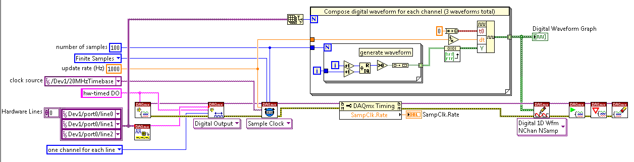
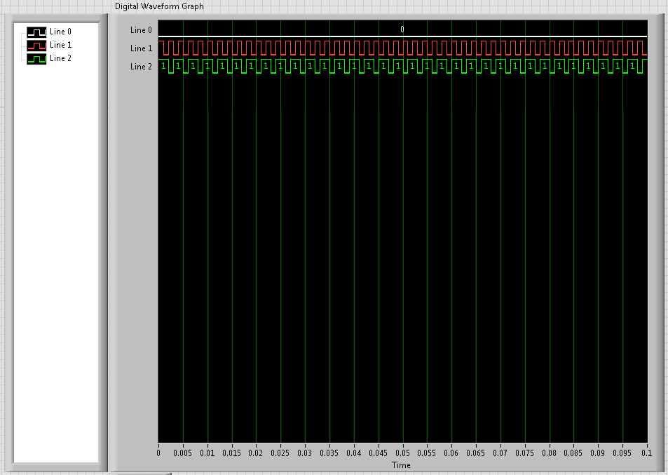
I use a PCIe-6537 and LabView 8.6 unit. This unit has an internal clock up to 50 MHz. I am trying to output a digital square wave at the maximum rate of 50 MHz I put my 50 MHz clock frequency, build my table of 1 and 0, convert it and the digital waveforms (on port0/$line0 if it makes a difference) output. During playback of the wave on a scope it shows a [very] good, but only 25 MHz square wave. The reason for which I believe is being only a sample of output (1 or 0) DAQ card for each rising edge of the clock and not fall. This is why the output wave will always be twice as slow as the clock frequency. Is there a way to power on the edge both amounts and descendants of the sample clock so that I can get a square of 50 MHz, wave or should I try a different technique?
I'm all ears...
~ JS
ISO
The ability to generate/acquire both the rising and falling clock edge is called double rate (DDR). We have an application on the use of DDR note with our instruments.
Of the advanced features of digital devices: Double data rate
The Board you use, however, is not capable of a double speed. The only devices capable of DDR at the moment are the NI 6561 and NI 6562, which were maps LVDS. You can get out on the forehead or the edge down, not both. You can use an external circuit to generate a signal of 50 Mbps. Basically, would need you an XOR gate and combine two different ways to create a signal 50 Mbit/s on a 50 MHz clock frequency.
Here is an example of how you can achieve. The white paper I mentioned above will guide you in this process.
On the other hand, we have boards of 100 MHz that will give you a square of 50 MHz, similar to the desired wave. The NI 6542, 6552, 6544 and 6545 are all 100 MHz or higher. The SMU-6545 is a 200 MHz Board. You can use one of these tips to generate higher frequency signals.
Hope that helps. I would like to know your opinion on this.
-
Why my digital output give 1V instead of 5V?
I have a PCI-6030E. When I look at its digital output to port0/$line0, I see 1V instead of 5V when it is 'high '. He read 0V when 'low '.
Any ideas?
Amit
The only other thing I can think is that you don't have a good connection to DGND during the measurement or the line is maybe configured as an input. If this isn't the case, the card may be faulty.
-
take the digital output USB-6001 always high or low in c
Hi all
I am new to the NI DAQ interface. I have a USB-6001 and I am trying to use this device to control some flowchart in C. What I want to do is:
* set digital output lines with high and low intensity and change their status as needed (in C).
I tested the device NEITHER Max--> Test panels and found that the device is capable to do that. Then I try to do in C. I have checked hace examples and function I use is one called "DAQmxWriteDigitalU32". I have problem in the understanding of its input parameters. I tried something with my own knowledge, but it does not work as I expected. Here is a test I did:
data uInt32 = 1;
Int32 wrote;
TaskHandle taskHandle = 0;
DAQmxErrChk (DAQmxCreateTask("",&taskHandle));
DAQmxErrChk (DAQmxCreateDOChan (taskHandle, "Dev1/port0/line7", "", DAQmx_Val_ChanForAllLines));
DAQmxErrChk (DAQmxStartTask (taskHandle));
DAQmxErrChk (DAQmxWriteDigitalU32(taskHandle,1,1,10.0,DAQmx_Val_GroupByChannel,&data,&written,));taskHandle = 0;
DAQmxErrChk (DAQmxCreateTask("",&taskHandle));
DAQmxErrChk (DAQmxCreateDOChan (taskHandle, "Dev1/port0/$line0", "", DAQmx_Val_ChanForAllLines));
DAQmxErrChk (DAQmxStartTask (taskHandle));
DAQmxErrChk (DAQmxWriteDigitalU32(taskHandle,1,1,10.0,DAQmx_Val_GroupByChannel,&data,&written,));I just want to set ' Dev1/port0/line7' and ' Dev1/port0/$line0"at a high level, but only ' Dev1/port0/$line0' answer me. The second parameter of the DAQmxWriteDigitalU32 function is numSampsPerChan. If I replace (currently 1) with a higher value, such as 100, I see that "Dev1/port0/line7" sends a number of 1 output, then back to 0. So I guess that the problem is just that I understand not all parameters for the DAQmxWriteDigitalU32 function. Is someone can you please tell me how I can set up a line of digital output 1 or 0?
Thank you!
Hongkun
Hello
I finally find a way to do it! The feature works very well, and my problem was not set the data value to write correctly. It seems that if I want to write a 1 to the port0/line1, I put "data = 2 ^ 1" rather than "data = 1", because by default it is the second bit of the port.» Similarly, "data = 2 ^ 7 ' high level to port0/line7. I find that this setting is surprising when you want to control an individual line. It seems more reasonable when you control the whole port. In any case, is to solve the problem!
Thanks anyway!
Hongkun
-
analog sync of input with the onset of the digital output
I'm trying out an analog signal to a file with a specified frequency samples. I also need a digital output to trigger a measurement at a frequency specified on a separate system. The frequency is controlled by the loop exits and timed when the iteration number divided by the period is exactly a whole number.
Both outputs work. The problem is that they are not synchronized. The analog output amounts to about 0.5 ms faster than the digital signal. (I checked with an oscilloscope) They both start in the 1 ms each loop runs for, but I really need them to start at the same instant. What can I do to synchronize? Also, if I'm going in the wrong direction complete, please indicate.
I use a card PCI-6723, which I think someone at some point, said not having a material sample clock. That's why I try to use a timed software loop.
Hi NEA.
You must use the 6723's built-in calendar to accomplish what you want. As the digital output subsystem is only clocked by the software, an appropriate solution should be to use one of the counters to the pulse output.
The attached code should show how. You can use the counter to output a pulse all samples of the AO N task. Material requires the initial delay to have a minimum of 2 ticks, so the meter will be behind the task of the AO by 2 samples in this case. There are different ways to work around this problem if you need (for example write two samples of 0 first).
Best regards
-
clock calendar - digital output
Hi all!
I need timing equipment impliment on a few digital output lines. That's what I have so far:
I didn't get an oscilloscope for her yet, but I'm fairly certain that it works. Please note that in this example, I use a PCI-6115. I have 2 questions:
(1) make what I do look reasonable at a quick glance?
(2) I'm kinda mistified by the entry of clock source to the example of the clock function. The analysis that I read just still confuses me. I understand that the clock is what dictates the sequence of material. I do not understand how to choose the appropriate clock source correctly. More specifically, in the above example, I've only had the program work when I chose "20MHzTimebase". What is c? Why this work?
When I try to select ' Dev1 / / SampleClock ", I get the following error:"attempted to perform a route when the source and destination are the same point."
When I try to select "Dev1/PFI0" or "RTSI0/DEV1", I get a timeout error in the wait_until_done.vi--> it does not appear that the waveforms are executed.
That means the PFI and RTSI acronym for, and why they appear as options when you select a source of the clock? Furthermore, why have they not worked as a clock source?
I would be very grateful to anyone who could clear things for me a little. Thank you!
Have you read the http://digital.ni.com/manuals.nsf/websearch/01C075FB9478F94A8625786A007435BA? manual The definition of PF and RTSI are here. They are designed using external clock signals. You have the choice of using the internal clocks of analog output (20 MHz) or external clocks. If you do not connect the RTSI bus or PF what, whether you have no clock so no data will be output. Selection of as source does not work because it is not a source. You provide a source for it.
Maybe you are looking for
-
Web pages empty every time, even when I work around cache!
I checked with managers from sites that the pages are not really empty. But firefox only shows the Virgin every time. (Even when I bypass cache by pressing SHIFT and click on the update.) How can i solve this? Here is a space that should not be: http
-
When I leave the ENVY printer for a while, I don't know how long to say from one day to the next, it never wakes. I have to pull the plug and then put in back in to restart the computer to make it work. Of course, another computer connected wireless
-
Finish the installation of Windows after the restoration is not possible
Hi, I have a problem with my laptop. All of a sudden the keyboard reacted as the SHIFT key is down. When I insert a cd I don't have the name of the file under the icon and firefox lost my favorite pages. I ran antivirus scans, but nothing came. so I
-
WiFi works does not even after installing drivers
Recently I bought HP compaq 15-s006TU and the wifi does not work in windows. Press the keyboard wifi is always orange. I tried to download and install the drivers wifi and bluetooth from the following links: http://h20566.www2.HP.com/portal/site/hpsc
-
Windows Movie Maker, save my video on DVD
Original title: Windows Movie Maker. I have Windows Movie Maker, I have XP Home + SP3, how do I save my video to DVD (I can use CD, why? * address email is removed from the privacy *)