PID inverso (enfriamiento)
Normal 0 21 false false false MicrosoftInternetExplorer4 st1\:*{behavior:url(#ieooui)} / * Style Definitions * / table. MsoNormalTable {mso-style-name: "Tabla normal" "; mso-knew-rowband-size: 0; mso-knew-colband-size: 0; mso-style - noshow:yes; mso-style-parent:" ";" mso-padding-alt: 0 cm 0 cm 5.4pt 5.4pt; mso-para-margin: 0 cm; mso-para-margin-bottom: .0001pt; mso-pagination: widow-orphan; do-size: 10.0pt; do-family: "Times New Roman"; mso-ansi-language: #0400; mso-fareast-language: #0400; mso-bidi-language: #0400 ;} "}
Buenos dias,
Escribo para pedir ayuda con Programación of UN PID temperatura mediante Labview utilizando las herramientas "PID control. The para este PID Cooper you're action reversed, en vez d, os explico el operation del sistema y lo that wants to get:
El control lo quiero hacer sober UN generador, el cual en 25ºC begins go to gearing progresivamente until reaching los 65ºC, lo cual no're recomendable para el sistema. What I want to get don't con maxima temperatura to control the PID, pongamos 50ºC, as el sistema el seria no superar should. Los elementos controlados would be unos ventiladores, asi pues solo podrá enfriar el sistema.
He intentado hacer con screws of PID control pero sirven todas las herramientas para Acción directa (calentamiento) y yo Necesito UN action reversed (enfriamiento) para el sistema keep estable en 55 ºC.
Awaiting that me podais help,.
Gracias photos,.
A greeting
Normal 0 21 false false false MicrosoftInternetExplorer4 / * Style Definitions * / table. MsoNormalTable {mso-style-name: "Tabla normal" "; mso-knew-rowband-size: 0; mso-knew-colband-size: 0; mso-style - noshow:yes; mso-style-parent:" ";" mso-padding-alt: 0 cm 0 cm 5.4pt 5.4pt; mso-para-margin: 0 cm; mso-para-margin-bottom: .0001pt; mso-pagination: widow-orphan; do-size: 10.0pt; do-family: "Times New Roman"; mso-ansi-language: #0400; mso-fareast-language: #0400; mso-bidi-language: #0400 ;} "}
Buenos dias Arturo,
Last week al final very perform a PID to ASIL a los requirements than expuse en el anterior message.
Muy than el PID is ejecutara of forma reversed (enfriamiento) introduciendole una Kp together observe el behavior del sistema con el resultado of as el sistema era estable pero con one error of 5º, worm despues como Kp together me servia para hacer el control of enfriamiento dispuse a tune PID por medio Ziegler - Nichols el y verdad los resultados hasta el momento are being buenos. Aunque el recoger he tenido output Beach del PID (10-100), is that the config led PID has paraba veces y arrancaba a Tope, lo cual los ventiladores not beneficioso are.
Comentar than no tengo el PID incluido, pero tambien seria I think case dentro a buen complement para mi sistema.
Gracias por you Arturo ayuda.
Kind regards
P.D.: No. I can open el vi me envias ago mi Labview are version 8.5
Tags: NI Software
Similar Questions
-
Satellite L850-1V8 - 'System' process (PID 4) uses 100% of CPU
Hello
I have a Toshiba Satellite L850 1V8 with windows 8.1 64 bit on it.
I encounter the following problem: some times when I start the system, the 'System' (PID 4) NT kernel process begins to spin, taking up 100% of any one heart.
This happens about 3-5 minutes after that the system is in place, but a few times I saw him from the hours later.
I have to restart the system to make this problem go away.Someone at - there experience this problem?
No idea where to start looking for a solution?These processes can be associated with any software / application running in the background system
But I know kernel NT & system could be generated by http.sys uses port 80.
That would mean that and would mean that a piece of software like IIS (internet Information services) could be responsible for this process in the background.
-
Basic concept of loop PID closed
Hello
I have a problem of very basic concept of PID loop closed. I read a lot of material of the PID controller but still confused.
I understand that the error between the measure and the desired will be processed by PID controller, but I do not understand how the controller output (sum of three P/I/D) set the right plant behand the controller. For example, an electric motor fan will be below on a Board, the force of the wind on the motherboard could be detected by the tension and of course the fan speed could be adjusted by tension. But the error of the setpoint and the process variable will go directly to the fan in Labview without identifying the mechanisms on the plant (fan). I wonder if anyone knows how this error is treated by the plant. And why we need not care about the transfer of the factory function.
If you have a transfer function for your plants, you don't need PID, because the output of the optimal control can be determined directly from the transfer function! (Well, more specifically, often in this case you would use the transfer to feed-forward control function, which you would combine with PID to correct minor variations between the reality and transfer function model.)
The output of PID is not a sum of errors. It is a sum of the outputs of regulation - the proportional output, the full output and the derived products output. The gains set the regulator to the specific system, and if they are not chosen correctly, the control will be terrible and potentially unstable.
In your hypothetical example of two systems - Yes, it is quite possible that one moment the error and so the output will be the same. But if the systems are very different, the next iteration of control errors will be different, so the next controller output value will be different, etc. And if the systems are very different, they should not have the same gains.
-
15 - r018dx: is the PID of Win 8.1 in the BIOS
I am repairing a laptop of neighbors who have experienced a fatal disk crash (it's toast). Installed a new drive HARD but have no recovery media. I see various places in market there are recovery kits 8.1 cheaper than at HP, but without a PID. I need confirmation that HP incorporates the OEM PID in the BIOS, which will allow to install after market recovery kits. Is this correct? TMB1
Yes, HP incorporates the OEM PID for Windows 8.1 in the BIOS. This Windows PID is 8.1 of Windows OEM specific and may not work with third-party recovery media unless it is an exact copy of the HP recovery for this exact model of HP media. There is no guarantee that any recovery of spare parts kit does not work correctly. I suggest the purchase of HP's HP recovery media factory. Please see DVD - 8.1 64 bit of Windows Recovery Kit / Kit for portable consumer (4 discs) system recovery for the purchase of this media.
If you have any other questions, feel free to ask.
Please click the 'Thumbs Up' white LAURELS to show your appreciation
-
Hello world.
I wrote a program of temperature control in labview and used the PID Toolkit for it.
The entrance to the PID is the measured temperature and the output is a PWM signal fed to a relay that turns heater on or off.
The control works but I want the temperature to be stable within a range of + - 2%.
Currently, the temperature varies more than that.
IAM sure, this is the setting of the PID.
Because I have not worked with regulators PID Iam not exactly how to tune my system.
The best way I found is to zero I and D and make the system oscillate with P.
The only problem is that the system of temperature is so slow that it takes quite a long time to reach the set point which in turn would mean a lot of hours of tests only.
Now Iam just wondering if there is a faster way to set the PID controller?
Thanks in advance,
Best regards
Michael
I've used this method several times with slow heating appliances. It can take a long time to reach a stable temperature, but at least do not monitor constantly as he approaches this value.
In figure 3.4, Yes, the Min value is the initial value that is stable. It is OK to start an initial PWM output of 0, which speeds up the process, if your radiator is already at a steady temperature (the temperature in the room).
In general, the difference between the output of the first and the last values, better will be your control (you will get best results of going from 0 to more than 50% to 5%), but it will take more time to settle to a new value and of course you must ensure that you do not exceed the capabilities of your system. It's a good idea to have a separate alarm system in place that can cut power to heater if you exceed a temperature, especially if you plan to walk away from it until it stabilizes.
To a fixed cycle, the system will not continue to heat up indefinitely unless you have a perfect insulation without heat loss - but, as I mentioned above, do not choose a value that will not cause the system to overheat.
-
State Machine with PID control
Hi, I currently have a problem with my state machine, I control two cylinders double effect in sequence that works very well. However, there is one point I need to increase the pressure in the cylinder and to maintain this pressure through the sequence of State machine, however when the state machine transitions to the next indicate the PID controller resets, how can I solve this problem? Everything in is also allowed to apply the pressure in the cylinder another (same node IO accessed).
Thank you I joined my project in a WinZip file, then it will have to be extracted. The two main VI to watch is 'Park Brake FPGA VI New' and 'park brake host VI update 2 "(new)
Thank you.
Nevermind I solved the problem with a parallel loop.
-
OBD II enhanced PIDs with a/d converters
The ADCS takes by recovering the extended PIDs or improved through service $22, as specified in J2190? Or supports only services $01 - $10 as specified in J1979?
Manual linking Hoovah watch it takes in charge ReadDataByIdentifier, which is $ 22. These services are usually referred to as UDS (ISO 14229), but there is a lot of overlap between all the different specifications.
-
How can I connect PC to the PID block when there is no block to HAVE?
Hi, I've just started using NOR-FBUS (NI USB-8486 with Configurator OR 4.1)
for my device configuration, there is only block AO, tuberculosis, RB and PID.
Question 1.
Can I manually set SP in the Configurator? If so, can you please tell me how?
Questino 2.
I tried to follow the tutorial in the manual, but I did not block of I... so how can I
wire of my SP to the PID block?
Much appreciated,
Thank you
Hello
Have Weiwei VALUE should follow the change in TB after adjustment. But you couldn't change it manually.
Here, I've prepared a PPT on how to create a PID loop.
FOR INFO.
Good luck.
-
PID.h necessary even if I included
I recently to explore the possibility of using the Labwindows PID Toolbox instead of my own out of sake of interest. I ran a few examples very well. When I implemented in my application, I included the following header files
#include "PID.h".


#include "asynctmr.h".
Even though I've included PID.h it gives an error
The following include statements are needed in "myfile.c.
#include "PID.h".
You want to add them after the include statement for windows.h?
I have of course included but wonder if I don't have something set up correctly in my environment. I should also mention that this is performed on a real-time target. The seemingly useless included headers are there because I have a file that is compiled into windows and LVRT and handled with directives #if _LINK_CVI_LVRT_.
I provided the activation key earlier yesterday and have rebooted the system. I can run the examples very well. Any thoughts or ideas?
Finally, he was an old pid.h of file that ASO hiding in the repertoire and was not included in the compilation for some time because now my own implementation of pid exist in another file somewhere, go me. Remove obsolete files, did the trick.
-
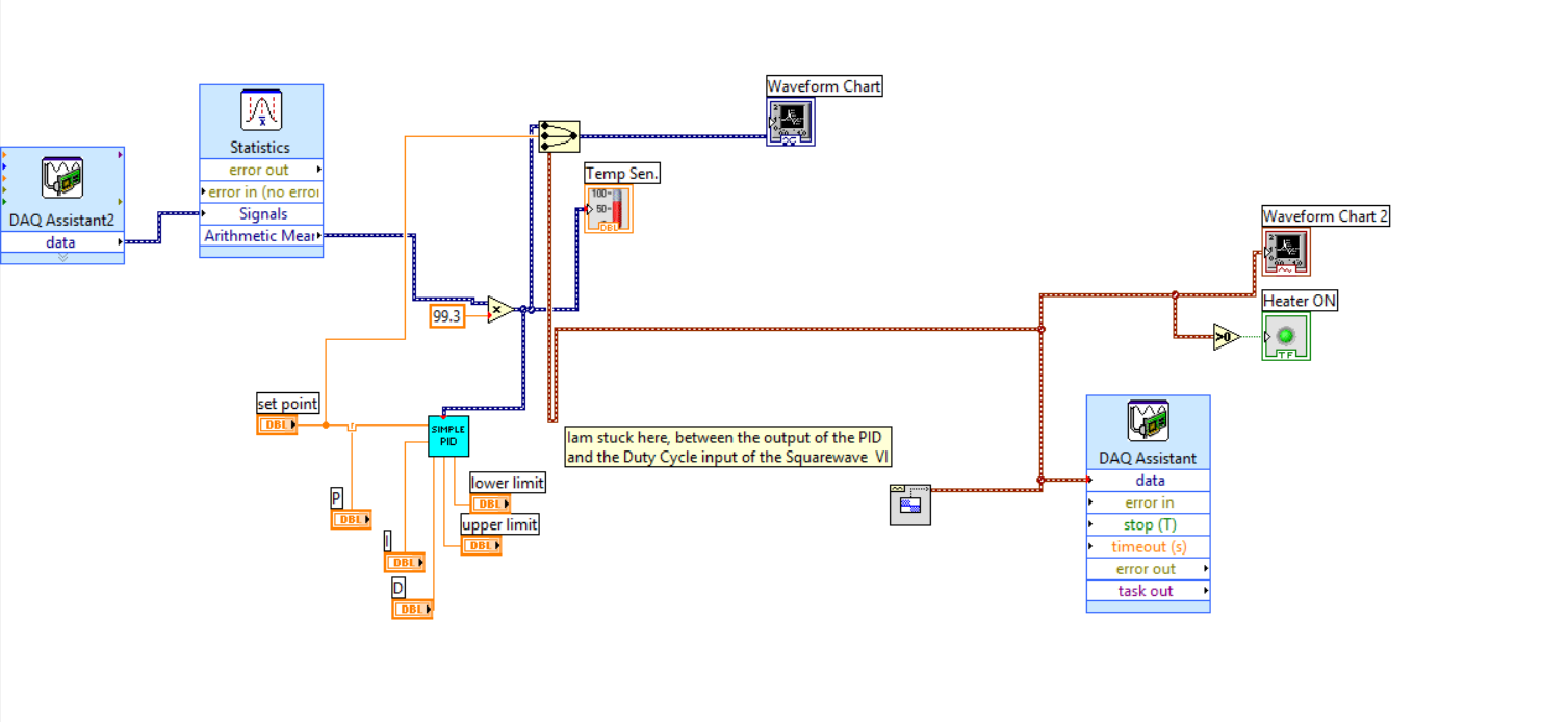
Hello everyone.
IAM working on a temperature of Labview control program that uses a controller of PDI, a radiator, a read thermocouple temperature.
IAM able to read the sensor and I think that I managed to implement the PID as well.
What I have to do now is to convert the output of the PID in a Cycle of use appropriate in % to enable/disable-energize a Solid State Relay for the power supply of heating.
To generate a square wave, I thought using the Waveform.VI of the place. (see image below)
The output for the PID is in the range 0... 5 v so I guess I do this output to scale in a way?
Thanks in advance for any help,
Best regards
Michael
I have not seen that VI PID single within a certain time, and if you have access to the PID toolkit (now included with versions of LabVIEW non-Base) you must use that one instead. In both cases, however, the limits of output are set by entries in the VI - in your case, the 'threshold' and controls 'Cap '. Change these so they are 0 to 100 and then use the output of the cyclical report.
-
Hello
I am writing to find out can you please help me. I am writing a program of PID control for a water level control project that I do but when I use labview and select a daq assisitant it does not show onit terminals so that I can't thread it upward. Can you please help to fix this.
Try this...
5GDBD9ZL Knowledge Base: DAQ Assistant fails to generate entries or exits when it is configured
-
Command PID made al control of DC motors
Hola a todos
Alguien me could asesorar con el uso del PID toolkit there that manera lo puedo more al control of 2 DC motors, con doble cuadratura encoders
Buenos dias, Diego,
SIGA el enlace para descargar el PID Toolkit. Any pregunta por favor póngase in contacto con nosotros.
LabVIEW PID and Fuzzy Logic Control Toolkit 6.0 - update for LabVIEW 8.0 - Windows
http://Joule.NI.com/nidu/CDs/view/p/ID/603/lang/en
Carefully,.
-
I use the full version of DASYLab 8.0, how to add PID module in the design of the façade (window layout)? while I can vary the p, i, d values in the window layout
To do that you will need to change the varibles PID values and then use the sliders to add numbers to a latch for variables that point.
This is how I think it works in Version 8.
In all cases, you should move on to 12 more stable summer.
In addition, unless that is a very slow process, I generally do not like closed loop PID with DASYLab due to the fact that computers is not reliable with timing.
-
PID parameters change manually on page layout
Hallo,
How could I change the PID / settings Kr, Tv, Tn manually from display layout in Dasylab. Can someone help me? Thanks in advance.
I also don't think that you need to synchronize the cursor with the release of the MIP. If you want, you should do with the entry.
-
FPGA Express PID vs Custom PID behaves differently? Whats is wrong
Hi all
I try to use labview FPGA Express VI in my application with cRIO 9022. I write a custom PID and compare the result with the FPGA palette express PID.
It seems that the integral action on the express PID is too large.
I am using PID as a simple Integrator providing zero gain proportional and derivative and Ki = 1. Which provides a signal error of 0.1 and sampling time of 1/5000, after 10 sec, the Integrator must accumulate 1. As usual, we he reach apprx. 10 sec, the express VI increases quickly until saturation.
What is the problem with my VI, I'm sure I'm missing something. The reason why I want to express is that it consumes less space and I have to use 5 parallel PID which I just can't get with a custom because it is written not effectively. I attached the VI and the png for your view.
Thank you all,.
Some.
Well, the ZIP file is valid, but I'm on an older version of LabVIEW, so I can not even open your screws, sorry.
I would check your math. Aid for the VI Express FPGA is clear on the functioning of the calculation. It does not count the sample time - which is one of the reasons that gains are standard. Configured the way you need your code, the error integrated - and therefore the output - increase 0.1 for each iteration of the loop, regardless of the rate of loop - so it will take 100 iterations for output reach 10. You can set your full winnings to take account of the actual loop cycle time.
Maybe you are looking for
-
How can I remove the filter TB bar?
In earlier versions of TB, you may hide the filter bar. How can I do this in the new version? I don't want to show him.Thank you ~.
-
SE sec_error_inadequate_cert_type with private SSL Cert
Howdy, I run a certification authority private for personal use and only to learn more about SSL Certs. However, with the current version of FireFox I'm on (31) I can no longer visit the sites that I secured with SSL Certs that are signed by this CA,
-
Windows Server 2003 cannot log on and say: issas.exe (service dirctory file does not exist)
I want to help meI want to recover my operating system
-
Static IP for Smartphones blackBerry via WIFi
Hello For my research, I need to connect a 8900 "BOLD" to a wireless gateway that does not DHCP or DNS. I am able to assosiate with the gateway and assign a static IP address for the BB. However I can't ping the IP address of the gateway. I can't do
-
HelloHow to convert a 2D to 3D ImageCreate a video with always shoot in 3dOld Photo converted to 3D as video 2d(Photoshop and After Effects)Thank you