PtByPt square signal generator for output FPGA
I'm currently building a host vi in which I can choose to send a square wave or a constant value in the analog output of FPGA. I know this might solve using the square wave generator express vi in FPGA.vi, how ever, in order to save using the FPGA card, I want to use the generator function from signal square on the host vi.
The first problem I encountered was square wave generator outputs feature a table instead of a ladder, so can not connect to the output function FPGA I/O node. Then I tried square wave PtByPt. However, the functino description is a bit vague for me. What I get now is a constant value defined by amplitude instead of a square wave. If I set the amplitude to 4, then the wave is a continuous line with a value of 4, and if it's 4 or - 4 depends on the frequency I put. I don't know if it is caused by the definition of wong of the time parameter of the function.
Can someone help me understand how a square on host vi of output wave? Thank you.
Here's the same VI to 8.5. I hope that helps!
Gregory C.
Tags: NI Hardware
Similar Questions
-
calibration of Agilent N5183 Signal generator for specific output level
Hello
Newbie to labview environment! I'm writing a VI to calibrate Agilent N5183 to a specific output. For example if I want to have-4.5 dBm output of my installation (as stated on my electricity meter) I'll have to set the sig gen to say 7 dBm given my losses, etc.
How can pointers, I start to weld it? I think I'll have to create a while loop to check the levels of power, but I don't know how to increment and decrement the amplitude of sig gen and stop at the desired level!
Thanks in advance for any help.
PS: With the help of Labview 2013, on win XP!
mkossmann wrote:
3. adjust the pout to sign Gen to the desired level, while controlling the power power meter
Why is it that step at all? It is not clear from your description, what makes the difference between the reading of the gauge and the output level of the sigGen parameter.
I have done many times. Especially in the RF field, you want your tests to have a certain level of power to the object to be measured. We therefore have to adjust your signal generator to compensate losses in cables, couplers, etc.
To do this, all you have to do is set your generator to the desired level. Then measure with the power meter. Subtract the measurement of the desired and add that much more to the output. Repeat if necessary. I advise to use a conditional TO the loop so that you can easily set a limit to how many times adjust you (I've been in infinite loops due to the weird situations here).
-
Hello
I want to do a continuous waveform. There are samples and files online to do it, but I would like to be able to change the frequency of signals continuously, I mean something like a function generator. I try to use the channel of PFI in NI 6221, but it provides just the waveform with a constant frequency. I wonder if it's a good idea to use the channel of the IFP? I want to give 100 kHz square wave.
Thank you
Hi Saridar
Thisexample may be what you are looking for!
Concerning
-
generate a square on the analog output wave
I use a PXI-6229 DAQ card and I need to generate a square on ao0 wave. I'm programming in c# and have found an example of the expedition, which generates a sine wave. I need to be able to modify the function generator that was provided with the example of the expedition to produce a square wave 7.2 kHz with duty cycle of 50% and 2 v peak-to-peak. I enclose the code generator to function.
Thank you
After a lot of trial and error and adapt the example to generate a sinusoidal signal, I have the solution to generate a square signal of analog output. I enclose the code.
-
FPGA square wave generator diverts loop calendar
Description of the problem:
I have a simple while loop with a structure of matter inside. In one case, I have the
Generator FPGA Sinewave sending the data of output to AO0, otherwise, I have
the square wave FPGA sending output to AO0 generator. The sine and square
waves are set to run at 10 kHzI also have a shift register that changes the State of DIO0 each loop through.
In this way, I can look DIO0 on my scope and say how fast the loop runs.When I choose the sine wave generator, the output on AO0 is what I expect. That
is I have a sinusoidal signal at 10 kHz and the loop speed is approximately 1 US. Everything is good.Then I move to the square wave. I get a signal square 10 kHz, which is good. But
My loop speed was slowed down to 50 US (it follows the square wave
exactly) is: once the loop defines the FS square wave and the
the next time through the loop, it defines the square wave to-FS.My problem is that when I generate a square wave, I expect the speed of loop
to stay fast he does it for the sine wave. You can see what my loop speed
slows to 50 (a square wave of 10 kHz) and then all my calculations that must
go in parallel with the square wave will also be slowed.Please help me with my understanding of the use of the square wave FPGA sub - VI
Thank you
RichSoftware of NEITHER: LabVIEW FPGA Module version 2013 SP1
OR hardware: USB-7855R R Series deviceIf you dig into the express VI, it will loop an SSTL until there is a change in value. The sine wave has no need to do so because the value changes constantly.
If you can, I recommend doing your loop a SSTL and configure the express screw accordingly. This will work as long as the rest of your code in the loop can be run in a single clock cycle.
-
Output a TTL HIGH 10 usec via the PFI port on AWG signal generator
LV dear community,
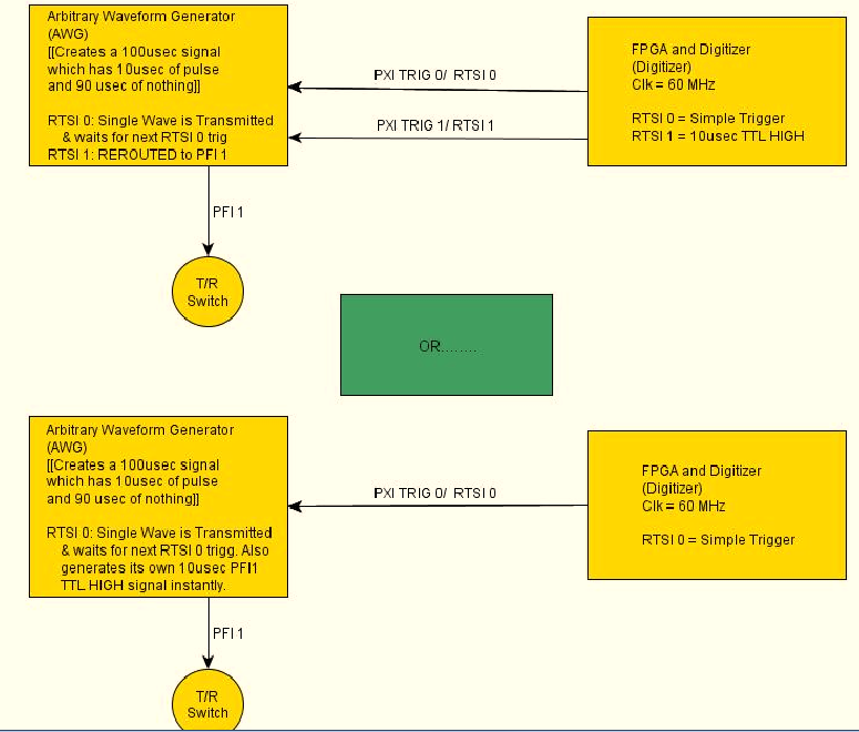
I want my signal generator (PXI-5422) to produce a pulse of 10usec with its PFI1 range each time that a wave of exit CH0. The frequency of repetition of the CH0 impulses and the port of PFI1 is 10 kHz. Is it possible for the signal generator automatically generate this HIGH TTL signals for usec 10 on the PFI1 line all at the same time produce a long-wave 100 usec?
Another approach, that I'm considering is to re - route a pulse of RTSI1 (10usec) from an FPGA and output via port PFF1 of the GTS. However, I doubt that this is possible, as the HELP MENU for the working group said that the report can only occur when the Working Group is in "idle" mode.
Any help will be greatly appreciated!
Have a nice day
 I have attached a diagram of operation that hopefully, explains what I'm trying to do a little better. Once again thanks for looking!
-Daniel
Hi Denn_Mann,
To get around the limit of 320ns, you should be able to use scripts with the FGEN markers to achieve your goal. Anything you want to do is use of script with markers in alternating mode. You may want to toggle high then low rocker after the number of samples you want pulse is high while your signal is present. I've linked some information below that should be good resources for script for you if you are not familiar.
Trigger on the arbitrary signal generators and advanced waveform sequencing
Creating an event marker in Script Mode
Script mode
Example of the expedition: "Fgen Arb Script.vi.
Kind regards
Ann Travis
-
[FPGA] Problem with the sinusoidal signal generator
Hello!
At first I want to apologize for my English is not my mother tongue.
Hardware and software I use is:
LabVIEW 8.5
NEITHER RIO 2.4.1
NEITHER cRIO-9014 (controller in time real CompactRIO)
NEITHER cRIO-9104 (chassis and FPGA)
NEITHER 9264 (16 channels, +-10V, 16-bit voltage analogue output Module)
I made a very simple FPGA VI: a while loop, generator of sinusoidal signal and a FPGA of e/s node in the loop. I've specified the Gnerator settings by following the path:
Frequency = 50 Hz
Amplitude = 1
Phase shift = 0.00
Size of the table look-up = 1024
= 16-bit amplitude resolutionFPGA clock frequency (40 MHz)
But the wave of "sine" I got is not what I wanted to get. First of all, its amplitude is 1 V. shouldn't it be coded on 16 bits? If I wanted to get 1V I should have specified Amplitude as a 3277. In addition, 'sine' is not very detailed, it's look like "steps", as many samples vere missing. What I did wrong? I checked the samples and tutorials, I did everything the same way. A I forgot something or not has not specify other parameters?
Thanks a lot for your help!
OK, I solved a problem. It's embarrassing to admit, but maybe this will help someone else
 I blame my inexperience
The main solution to the problem was changing calibration of calibrated RAW Mode. After that, everythoing works as expected. I had a problem with a sample because I was using a multiplier to control the generated sine wave amplitude. But... She was set to 1 in the sinusoidal signal generator. That was the reason for waveform Gradin. Please, don't laugh too much

In any case, thank you for an answer! It is now resolved
-
How to determine the number of highlight ' to write ' for DAQmx generate analog output?
On the configuration of the stage for DAQmx generate analog output, there is a field "value to write. I can't find any explanation for what it is, how it determines the value to enter, nor what he writes. I am trying to go through the tutorials and it cling.
Someone would give an explanation?
Hello
To write value specifies the value to write in the channels, lines or ports selected in string parameters. In other words, this value will be the value of your DC output (for example if you enter 5, your output will be 5V). To get information on different fields in SignalExpress, access help"context-sensitive help. A pane will appear in your work environment that displays the coordinates of the field when you place your pointer over them.
For new users of SignalExpress:
Generation of DC signals with NI DAQmx devices: step in the DAQmx build, select 1 sample (on request) in the generation Mode dropdown. You can select a programmatic input to generate, or you can remove the check mark from the check box use programmatic input and specify a value for generating in the field of value to write . NOR-DAQmx help also provides additional information about the data generation.
Best regards
M Ali
Technical sales engineer
National Instruments
-
Square signal of function generator does not have any straight edges
Hello, everyone!
In my job, I need to see the charge and discharge of capasitor. I have to use a schema on the photo attached to power the capasitor, because I'm going to replace it with thermoresistor, requiring a certain exact current level. I use a square wave generator functions as a service. But when I built my diet on the prototyping card and connect the generator, edges of the square wave become geometries and there is no lag CC that I set myself.
Can someone help me to know what is the problem?
Thank you in advance.
Hello samewings,
I took a bit of time and studied your wiring diagram. Your reading of the oscilloscope, it seems that you've done well to capture the loading and unloading of response of a capacitor already. For your information, you can compare your readings of the oscilloscope to the document I have provided below. You will notice that your corners of square waves are rounded as the loading and unloading of curves that are visible when the charge and discharge of a capacitor. A capacitor charge and discharge over time. For this reason, the voltage you read in all of your circuit will show this curve depending on the time on the edges of your square.
-
I want to do simultaneous 180 continuous signal phase (square) to 2 analog outputs
Hello
I would like to use a meter to trigger (internally) 2 outputs analog, such as the continuous AC signal to each output is shifted 180 degrees.
I hoped to do with no external connection in addition to the ao0 and ao1 was to use a timer as a trigger counter and have a trigger analogOutput on the front and the other trigger on the falling edge to get the required result.
However, it doesn't matter how I get there. An absolute requirement is that two continuous AC signals are present to ao0 ao1 outputs and they are out of phase by 180 degrees and all trigger occurs on the PXI bus with no other connections external that is frequency of 25 Hz. My card is an SMU-6363.
I was hoping to get the hardware to do all the work of relaxation but if there is a trigger of software approach that would be
Thank you
That's what I ended up doing. microseconds is quite good enough.
-
square pulse generated with the NI PCI-6723
Hello
I generated a pulse biphasic square in Labview using a standard square wave generator and by stopping the vi to run after generating a full periodic square wave period. The only problem I have is that as soon as I stop my code, so once the square impulse had emerged, the analog output of the Council NOR remains at the same voltage as the last sample of the generated square pulse. Instead, I'd like the voltage is back to zero.
This is the same phenomenon that you see when you use the Measurement & Automation when you build an analog output and then you stop manually, if you take a look with an oscilloscope to output voltage, that it remains at the level you stopped analog signal.
I have attached a picture of a pulse square with 1V amplitude and 1250 Hz frequency showing that voltage level will not return to zero. If I try to add a sample more to the curve above, the tension instantly bumps up to 1, leaving me with the same problem.
Any thoughts?
Thank you
Alessandro
It should work.
-
Wait signal generator complete the scan list before sending the next command
I am writing a program for Agilent E4421B signal generator scan to list between a range of frequencies (ramp up to the maximum frequency and then back down to the original frequency) specified. The signal generator has only a list of 401 points, which is a problem when I want to wash over a wide frequency range. To work around this problem, I would like to perform several scans of list in a row. However, I can't figure out an effective way to "say" the program to wait until the previous scan has finished before sending a new order of scanning for the signal generator. Any ideas? For reference, I use Agilent ESG drivers series LabVIEW.
Thank you!
If you use standard VISA calls, I would say just that send the scan command, but add; * mutual fund? (operation ends?) make a query. Then, run a VISA to read what's coming. This indicates to the device to send a 1 to the output buffer when the scan is complete (or just about any other operation, also). As you are waiting for a response, your computer will wait the amount of time to wait so he could see a response, it is not less, your way with the exact amount of time - no more - to be actually taken.
A few warnings:
(1) make sure that the time-out is longer than the length of most slow scan.
(2) there are variants of the '1' being returned. I saw '1', '01', and even "1.00E + 3" therefore to allocate more than one byte to read."
-
Why my signal generator point-by-point gives a flat line?
Hi all
I use the screw point-by-point for the first time and is trying to generate a square wave to use. However, when I plug the output of a point-by-point square wave generator, it gives just a flat line (using values default values for the other parameters). But it works fine if I use the point-by-point noise generator, it shows on the list. Any ideas?
See you soon
fact...
-
With the help of the external RF signal generator
Hello.
I just want to ask how can I remove the frequency shift if I use an external RF signal generator (instead of the RF PXI-5652 signal generator module). I understand that in the case using the OR to generate RF signals, frequency shift is deleted by setting the same source of reference for the transmitter and the receiver clock (placing the clock source of reference to PXI_CLK of the façade of generation VI and VI of the acquisition).
Thank you very much.
Hi Betty,.
In this case, no changes are needed, such as modules OR still use background clock basket PXI as the ref. clock source If you are still having a frequency shift, you probably need to configure sig gen to lock a clock external REF. Usually, just make the connection of the signal is not enough - you must also indicate the sig gen to use the signal connected to the input clock ref. Terminal
If you use the sig gen as clock source master Réf, connecting the 10 MHz of the gen of GIS at the BNC 10 MHz IN on the back of the PXI chassis replaces the clock native from the newly connected with the PXI chassis backplane, and analyzers are still using the clock background basket PXI as the source clock Ref (no change to the SW settings).
Kind regards
Andy Hinde
RF systems engineer
National Instruments
-
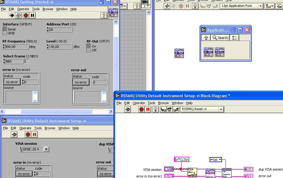
Why can't I control my LabView signal generator?
Why can't I control my LabView signal generator?
I put in schema-block function RSSMIQ (a function of the driver for my generator). I click on the RACE of VI, but compare a (red dot) interruption between the VISA ABC and ABC VISA and VISA SESSION flash icon. Why?
Automatically, it is open RSSMIQ DEFAULT INSTRUMENTS SETUP UTILITY and compare the figure downwards:
Is that a mistake? What? Why? I have fought with my generator WITHOUT ERROR?
Please see my response to your other post response No. 26 .
Maybe you are looking for
-
For eg., I installed the foxdie theme 4. He asked to restart to take effect. I rebooted and the theme changed to foxdie theme 4. But when I started the firefox for the next time, foxdie 4 theme disappeared. Firefox back to his previous theme. Its hap
-
The last time I went to Europe, I couldn't Skype who subscribed to the United States to work. I had to sign up again with a European version and when I got home I couldn't stop it and they kept me. I couldn't call someone and I couldn't stop it. How
-
Tecra 8000: Behavior strange keyboard after reassembly
Hello After reassembling the individual keys on my keyboard in Tecra 8000, the keys have a strange behavior. For example, if I press the 2 key the display shows '82' or 'q '. If I hold the button longer, the display shows "2222222222222...", the righ
-
Lenovo Z570 - how to disable automatic brightness adjustment?
It's driving me absolutely crazy! This only happens when I run the laptop out of the battery. And when I go to a website with a dark background, the display automatically dims down. Then when I'm on a brighter site, then screen lights back up again.
-
FPGA Virtex - 5 LX cRIO chassis
I noticed that the new chassis 8-slot cRIO is available in three different types: Virtex-5 LX30 FPGA Virtex-5 LX50 FPGA Virtex-5 LX85 FPGA What does the bolded numbers really mean? -Mike