PXI-6542
Hello
I tried to use static generation provided in the examples for PXI-6542 to write section of the values in the first 20 channels. When I gave the value in the list of strings like '0-15', the channels were driven to "high" as expected. However, if I mention the value in the list of strings like '0-20', channels 16-20 is not pushed 'high '. Could someone help me to fix this problem please? How can I assign mode static generation channels?
Thank you!
Hello testough,
Inside finder example OR for the static generation examples have a mask input channel. This default is set for channel 0-15. If you are wanting to have channels 0-20 generate data, you must update the channel mask to be 0x1FFFFF (a 1 for each channel).
I hope this helps
Tags: NI Hardware
Similar Questions
-
Test Panel does not work with the PXI-6541/6542/6551 in PXI-1002
Ripping my hair out trying to get the Test Panel can work with system as described below:
1002-PXI chassis with controller PXI-8176. In the three places available (from left to right) PXI-6551, PXI-6542 and PXI-6541. They come in NIMAX, they self test, reset and to calibrate. But when I try to open a Test Panel, I get an error as follows:
nidmfpan.exe - Application error
The application failed to initialize properly (0xc0000142). Click OK to close the application.
I uninstalled, re-installed, modified and repaired everything NIDAQMX (15.0.1) 15.0 HSDIO, NI-VISA (15.0.1), etc.
Original symptom is that when I pressed the button on the test Panel, nothing would happen. Then, the next symptom is that MAX has said MFC90.dll (not found) and MSVCP90.dll (not found) and MSVCR90. DLL (not found).
I can not find help topics or the forum messages that cover this. Very annoying.
Hi fully,
Sorry to hear that! Nidmfpan.exe is the process that opens MAX test panels and MFC90.dll is a Windows wrapper. Combinations of driver reinstall or copy other MFC90.dll files in System32 are unlikely to solve the problem.
You are on XP? Try to navigate to C:\Windows\System32 and rename the nidmfpan.exe.manifest to nidmfpan.exe.manifest.back and after close/reopen MAX file and try to open a test Panel. Is it effective?
Note that the file you want to rename is nidmfpan.exe.manifest and NOT nidmfpan.exe.
If not immediately successful, close and reopen the MAX and try the test panels a few times more. If after several attempts it still does not work and the correct manifest file has been changed, it can point to a deeper problem of Windows that requires a reformatting of the OS.
Really that's hope!
P.S. you might get more visibility to a problem as it is in the sections "PXI" or "Digital i/o. VXI and VME are not widely used these days, so this section of the forums is probably not too much traffic.
-
HSDIO - deterministic written submission during the generation
Hello
I use a card HSDIO (PXI-6542) to control a device (DUT) with a predefined fixed length, waveform continuously running.
That maybe had TO actually benefit from the dynamic changes in digital signals according to the measurements on the INSTRUMENT itself.
At the moment I just pass off the coast of the ASE and map HSDIO, write the new waveform on the map, turn to ESA and the generation of digital signals.
Of course, this is not optimal and I would like to change the way signal 'live', while the DUT is running.
Just crush a waveform, whereas it is generated should not be working smoothly due to a condition of race as explained here: http://digital.ni.com/public.nsf/allkb/14CE41C9CB9F10A88625766A005CEE47
I think that I've found a workaround, but need a confirmation about this.
Instead of just a waveform, I could use 2 and select which is generated using a trigger.
The corresponding script might look like this:
script myScript

  Repeat forever

          If scriptTrigger0

            generate a waveform1

          on the other

            generate a waveform2

          end if

  end repeat
For example, the idea is to generate a waveform1.
Then according to that CSA should I calculates waveform2 and transfer it to the HSDIO map.
I think here is overwrite waveform2 with the data of the same size will not create any small problem because it is not currently used to generate signals.
After this using the trigger, I could start using waveform2. If I need additional adjustment of wave shape I could do this by editing waveform1, so it is not used for the generation and thus now alternating serves really what waveform.
Am I correct in that a waveform in memory but are not currently used can be replaced without causing glitch on an another waveform that is currently?
Kind regards
Baptist
Hello, Baptist,.
Yes, you are right. It is a method to dynamically change the waveforms on the fly that was already used in the past. If you waveform1 to generate and download waveform2 then it is idle, it will not affect the generation of waveform1. Then, triggering via scripttrigger to waveform2, then you can download the next waveform, you want to use for waveform1 without affecting the production of waveform2.
-
several sources triggers digital i/o card
I use the NOR-HSDIO Express (Acquisition) with map of the e/s high-speed digital (pxi-6542), to a Logic Analyzer. It works fine but I need to use more than 1 source of relaxation, for example when 3 signals go data capture high (rising edge). I don't see a way to do it in the window properties HSDIO Express, any ideas please?
Hey svt4cobra6,
I would recommend that you first find the summary of triggers using HSDIO page, and I think that you want to use a Model Match Trigger. Then you should check the Model Match Start Trigger (or similar reference C ) specific help. This trigger allows you to use a row of data to look at multiple sources of relaxation at the same time. So, if you have additional data lines, then use 3 of them and use the 'R' or 'r' in your start of model match trigger. For example do not care your pattern corresponds to 3 rows of data where there is a rising edge on the 3 lines at the same time could look like this, where 'x' is:
"xxxx xxxx xxxx xxxx xRRR.
I hope this helps.
Kind regards
DJ L.
-
I need estimated MTBF for a list of products
Our system customer asked about MTBF. So I need MTBF estimated for the following of PXI products: PXI-6509, PXI-6542, PXI-7813R, PXI-8431/8, PXI-8432/4, PXI-7953R.
It is understood they are only estimates and will be accompanied by the creation. A full calculation 217 is not intended or desired. I got estimates of other systems of component suppliers. How can I get these estimates of NOR?
I did some more research on the calculation of MTBF numbers. In general, including this map, our MTBF is based on design, not fail rate field. The method used to determine this particular card MTBF was Bellcore question level II.
-
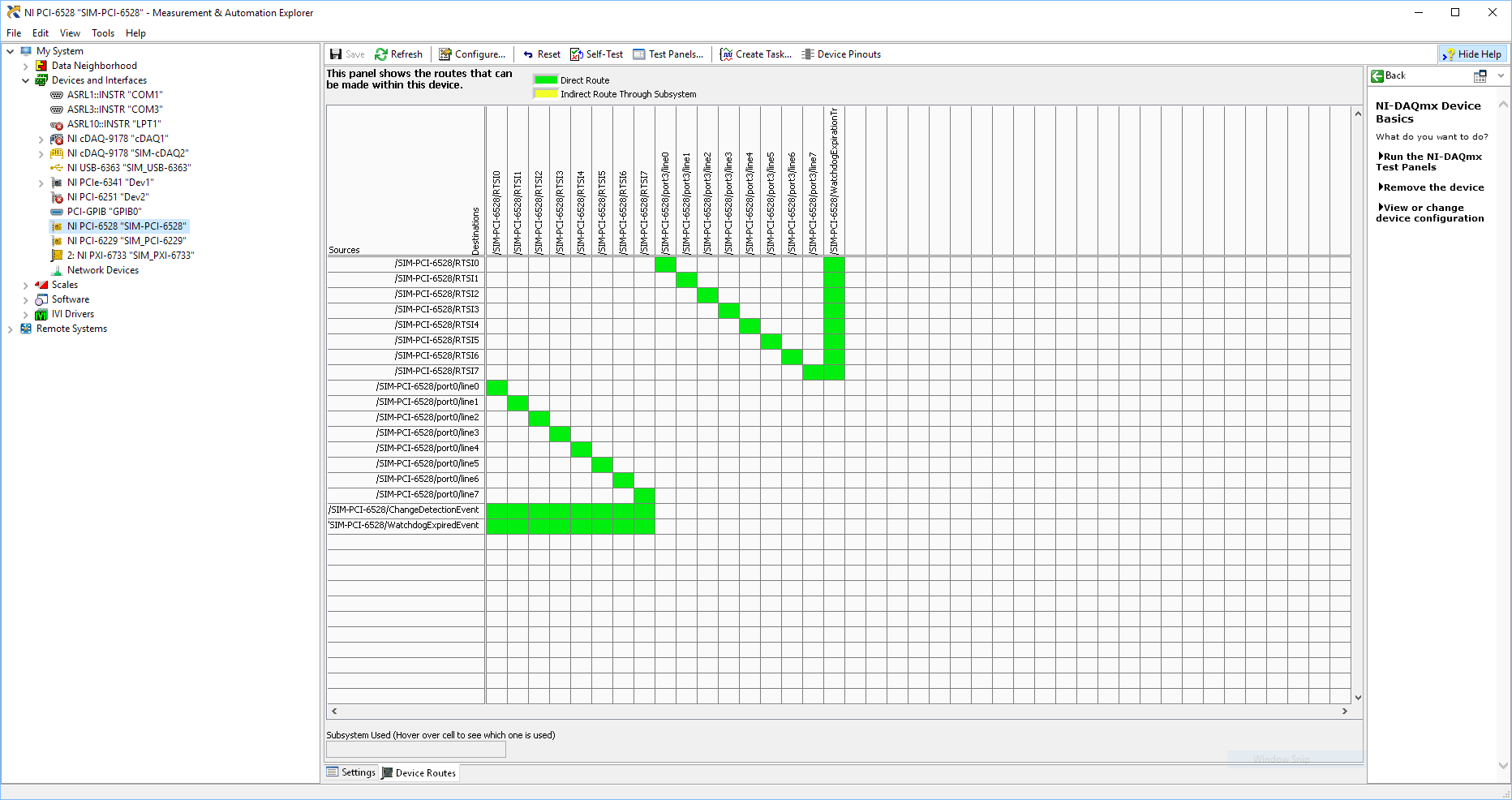
Using SMU 6612 to measure PXI-6528 pulsewidth channel - channel is not available.
Hi all
I use SMU 6612 card counter to measure the pulse width of the signals to PXI 6528 DIO card. These two cards are in the same chassis PXI (NI-SMU-1065). I could measure the pulse widths using the example LabVIEW 2013 Counter - pulse width of reading and (over) frequency example of .vi. However not all channels of the PXI-6528 map appear in the drop-down list of channels on the pulse width can be measured. Try to connect any other channel that those which are available in the drop-down list returns the error. On the PXI card port 6528 0,1 and 2 are entered ports and port 3-5 are output ports. I can measure the pulse on port 0, 3 width and line 0 port 1 and 4.
Can someone explain to me why don't see port 1 or port 2 channels in the drop-down list or force the VI to measure the width of pulse on these channels?
I can plug PXI-6528 external input channels SMU 6612 counter input channels and measure the pulse width, but if possible I'd like to avoid the external wiring between the 2 cards.
Probably not. Unless the routing plan is in fact reversed as it seems a bit sorta that. As stated on my system, you can route * of * a port of entry * to * RTSI, or you can route * of * RTSI * to * one output port. This does not make much sense to me, but that's what I see:
If the routing card * is * reversed, your only likely workaround without physical wire would be to generate impulses in question of port 3. It's pretty clear that 1,2,4,5-tetrachlorobenzene ports have no ability to interact with the bus timing, physical wiring would be the only option.
-Kevin P
-
PXI-1033 not detected until the pc is rebooted
We have a chassis NI PXI-1033 with a PXI-5114 and PXI-4072-PXI-6221, fist, that he had failed to recognize and install drivers for motherboards. The search in the knowledge base, I tried workaround by disabling the PCIe mode ' bcdedit/set pciexpress forcedisable' command and rebooted the pc. Then the system recognized and installed the drivers for all the hardware.
Disabled the PXI system at the end of the day. The next day, after activating the system, he did not recognize the hardware, returned changes to aid 'bcdedit/set pciexpress by default', then restarted the pc. Once again the material have been recognized.
I tried to change the configuration on the PC BIOS, without success. The PC is an ACP-4000 of Advantech. We need to restart PC after a cold start so he could recognize the hardware and load drivers.
Is this normal?
Concerning
The PC is under Windows 7 Pro. I searched on google for similar problems, where I found one where someone said that the culprit is that the chipset of the motherboard not give not the PCIe card delay what he needs on a start cold in order to be recognized. A reboot gives the time required and the card works.
-
Hello
I use a PXI-4070 DMM and DotNet "SoftwareTriggeredMultipointAcquisition" example
I want to trigger the DMM4070 with the AuxTrig entry to the front of the instrument.
This works very well, but how can I change the time out the of triigger?
It is now on 2000msec. I want to 10000msec.
When I us the example and do not trigger in the 2000msec I get error message saying:
ModularInstruments.NIDmm: The operation did not complete in time maximum allowed. Timeout: 2000mS.
Error code:-1074126845Thanks in advance
Wissam
Hello JaredRo
I can set the time-out period now.
Problem solved. Thank you Manny
With greetings
Wissam
-
PXI SFP 5105 configured Vs Acquisition VI
Hello
I recently started to use the NI PXI-5105 cards, I need to capture (noise level<20KHz) on="" top="" of="" my="" dc="" signal,="" i="" used="" software="" front="" panel="" to="" capture rising="" edge="" of="" an="" analog="" signal i="" was="" able="" to="" capture="" signal="" when="" it="" meets="" my="" trigger="" requirements="" same="" as="" configured="" acguisition="" example="" vi="" also="" vi="" recommended="" input="" signal freq="" ="" is="" 100khz,="" what="" changes="" i="" need="" to="" do="" in="" order="" to="" make="" this="" vi="" to="" trigger="" when="" the="" noise="" level="" on="" my="" dc="" signal="" exceeds="" certain="" point="" can="" anyone="" please="" help="" me="" with="" this="">
Thanks in advance!
Hey djo.
If I understand your description, the best sounds of relaxation as it can be a trigger of hysteresis with coupling AC trigger in order to eliminate the effects of your DC signal. You will then be able to adjust the amplitude of the noise that you are looking for as the level to which you want to trigger off. You can find information about the options available with the help of scanners trigger high speed OR under Fundamentals > trigger.
-
While with PXI-5122 digitizer loop counter
Hello world
I am a beginner of products NOR. Currently I use the PXI-5122, 2014 Labview for the ultrasonic signals. I have a problem when you count the number of signals using an external trigger (by a function generator) source. When I trigger the digitizer under 50 Hz, the meter is working properly (a single trigger = a signal). With a frequency greater than 50 Hz of trigger, the meter is malfunctioning. For example, with the shutter to 50 Hz and 500 number of signals, the counter takes 10s to get data. But, with the trigger of 100 Hz and 500 number of signals, the acquisition time was always around 10 s.
You can see the code in the file attachment.Please let me know if you have any suggestions or recommendations for my situation, I would appriciate that.
Thanks in advance!
Best regards
YouWorldALoneMe,
Looking at your code, you're software re - trigger your device. With your Setup, you configure the digitizer to hold a single record acquisition in your "A - Scan.vi". This VI opens the resource OR-SCOPE, configure, captures, returns the data, then closes the resource OR-SCOPE. It then does this for each unique A-Scan that you do and would be the reason that b Scan.vi takes so long. It appears then that fewer than 50 Hz, this reset any software and reconfiguration and the acquisition can occur without missing a trigger, but more than that, your triggers occur faster it takes to do these things.
What you need to do set up the digitizer to a multi-record acquisition. This is done using the 'niSCope configure horizontal timing.vi' and wiring in a number higher than '1' in the entry "number of records". "You can find an example of how to perform a multi-record acquisition if you open the Finder of example OR > material input and output > Modular Instruments > NOR-SCOPE > Getting Started > niScope EX Multi Record.vi.
In this example, the digitizer is only once configured, and it returns all the documents requested at the same time. For your application, each record would be a simple Scan of A, and then if you configure 500 files, your B-Scan would be 500 wide. This time allows the material to rearm between triggers that is much faster to do it in software.
For a verification of more complex example out (in the finder of the example) "niScope EX Multi record go get more available Memory.vi"
Kind regards
Nathan P.
-
5154 PXI trigger on the external input
I use a PXI-5154 and want to change my previous program to trigger the external source. I'm feeding the external source from source to V 2.5 and it seems to trigger fine. However when data acquisition the vertical range of the oscilloscope will 5 V which is too high as to my request I acquire in the millivolts range. I tried to show the vertical range of the channel I acquisition, but although I put it as the active channel I get the following error:
Error 1074118616 has occurred to the property node (arg 1) in PD_measurements_v11_test.vi
Get a base attribute value channel failed because the channels interviewed have different values. Please specify a channel when you query a string based attribute.
I enclose you a printsceen of the relevant part of the code.
Kind regards
Karavellas
Dear Tunde
I managed to make the changes you suggested and the works of the example. I'll look in my code and see what the problem is. I'll get back to you if it has been fixed in my code or not.
-
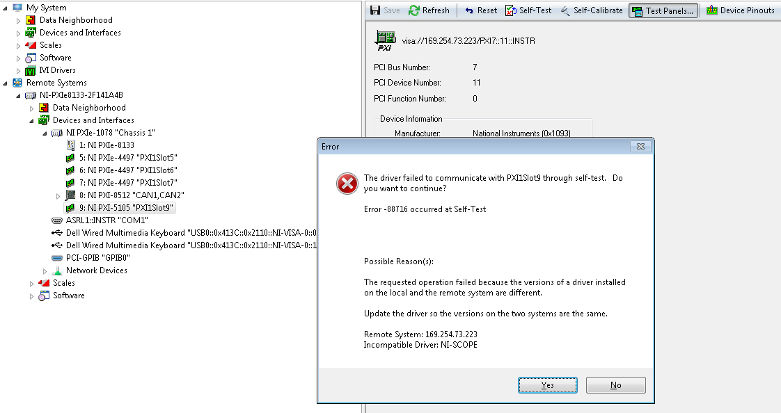
I am setting up test bench and just add a PXI-5105 card to my chassis SMU-1078.
I currently have NO-SCOPE 14.1 installed on my PC host and target RT.
When I try to run the Test panels in MAX, I get the following error:
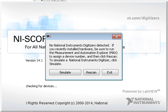
If I try to launch SFP-OR-Scope, it does not detect the card of the scope:
The map seems to indicate as normal in my remote systems in MAX.
For the host, the Installation of NOR-SCOPE includes:
- Configuration support 14.1
- 14.1 development support
- 14.1.1 duration
For the target RT, Installation of range OR watch as 14.1.0.
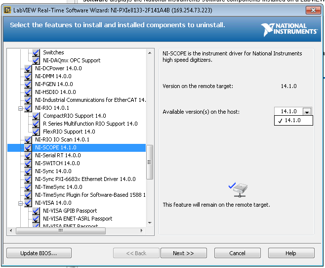
I even checked in the feature add/software for the remote system see if a driver incompatibility was actually present:
I have also confirmed in the Readme that PXI-5105 is supported OR-SCOPE 14.1.
I'm kind of dead in the water on other ideas to investigate on concerning the system is behaving properly with the new card. Other ways suggested for study?
I continued to play with setting up more and find my VI has been targeted my Windows host instead of the goal of the RT. I'm nowable to see my map of scope 5105 now through Labview + RTM. Thank you for tolerating a newbie.
-
How to identify a particular relay on a PXI-2532 module
I have a defective relay on a map of PXI-2532 matrix. I don't know who it is, but I do not know how to identify on the map itself relay. I would like to replace it. Any information would be appreciated.
With a few head scratches, it helped a lot. Thank you!
-
The streaming of data in c (PXI-5421)
Hello
I do the data streaming in C by PXI-5421 follow this instruction: http://zone.ni.com/reference/en-XX/help/370524R-01/siggenhelp/streaming/
Here's my psudo code:
1 set the amount of memory shipped to use for streaming
waveformSize = 1048576;
short * CurData [16];
checkErr (niFgen_init (resource, VI_TRUE, VI_TRUE, & vi))
checkErr (niFgen_ConfigureChannels (vi, ChannelName)); ChannelName = '0'
checkErr (niFgen_ConfigureOutputMode (vi, NIFGEN_VAL_OUTPUT_ARB)); //Arbitrary mode is used
checkErr (niFgen_ConfigureSampleRate (vi, SampleRate)); Rate of sampling = 40e6;
checkErr (niFgen_AllocateWaveform (vi, ChannelName, waveformSize, & wfmHandle)); Allocate memory for broadcast borad
2. identify the waveform streaming
checkErr (niFgen_SetAttributeViInt32 (ChannelName, NIFGEN_ATTR_STREAMING_WAVEFORM_HANDLE, vi, wfmHandle));
checkErr (niFgen_SetAttributeViReal64 (vi, VI_NULL, NIFGEN_ATTR_STREAMING_WRITE_TIMEOUT, 10.0)); Set TimeOut = 10 s
3. fill the waveform continuous initial data
for (j = 0; j<>
fread (CurData [j], sizeof (short), waveformSize/16, PlayedFile); Read data from my saved file
checkErr (niFgen_WriteBinary16Waveform (vi, ChannelName, wfmHandle, waveformSize/16, CurData [j]));
}4 start generating the waveform
checkErr (niFgen_ConfigureOutputEnabled (vi, ChannelName, VI_TRUE));
checkErr (niFgen_InitiateGeneration (vi));5 write a waveform data block. (Optional) Monitor available memory that generates the waveform
{}
niFgen_GetAttributeViInt32 (vi, '0', NIFGEN_ATTR_STREAMING_SPACE_AVAILABLE_IN_WAVEFORM, & FreeSpace).{if(FreeSpace>=waveformSize/16)}
fread (renewData, sizeof (short), waveformSize/16, PlayedFile);checkErr (niFgen_WriteBinary16Waveform (vi, '0', wfmHandle, waveformSize/4, PlayData));
//}
} while (1);I properly generate first 1048576 points of data. However, I'm stuck in writing new data in my space of memory onboard.
The error message space in continuous waveform has not become available within the specific period, and appears after 10 sec which is my time-out period.
If I check my available space via the property NIFGEN_ATTR_STREAMING_SPACE_AVAILABLE_IN_WAVEFORM, it never increases. Did I miss something? Can I work in arbitrary mode for data streaming?
Any suggestion is appreciated. Thank you!
Looking at the example LabVIEW/CVI, it seems that you are on the right track.
If you remove the Do / While loop, do you still 1114112 samples? In other words, samples of 1048576 (1048576/16)?
What is the value returned by ' niFgen_GetAttributeViInt32 (vi, '0', NIFGEN_ATTR_STREAMING_SPACE_AVAILABLE_IN_WAVEFORM, & FreeSpace)? "
I have attached the CVI example in this post. It has many additional functions that change the GUI of the CVI, but ANY function calls should be the same. Is the only thing that is considerably different that they set a number of rehearsals and use unique relaxation mode. I would go ahead and change your code to be similar in order to ensure that it is no hardware problems. Then I would try to generate and disseminate a sinusoid first before trying to use your file. I hope that we can refine all the problems.
Jason L.
-
I'm creating a test set-up and we probably intend to use the PXI-2568 (and the mating cable) to connect, but want the cable directly into my test setup. I think that there are a few standards D - 62, and I do not have the PXI-2568 module still to test.
What (for example) a connector suitable for mating with the PIX-2568 cable?
http://www.digikey.com/product-detail/en/Te-connectivity-amp-connectors/5749639-1/A31926-ND/808312
Hi Osbock,
The connector on the PXI-2569 is a standard 62 connector pins D - SUB, male, so it turns out that the connector that you found should work for your test setup.
I looked at the section "Accessories" of the data sheet and a female front connector, it says 62-pin D - SUB, female of any manufacturer, so I expect the same thing to the male connector on the other end of the cable.
Maybe you are looking for
-
is thunderbird a total direct replacement for outlook using W8.1
Want to swop to / 2nd hand PC, W8.1 & outlook, outlook is uncertain and I don't know the user name and password to complete. Microsoft account as uncertain. Can I load Thunderbird as a complete replacement for outlook account /Microsoft? If so, can I
-
When I click on the menu 'Add a contact'-> "Skype search directory", nothing happens. Therefore, I'm completely unable to add contacts. No error messages, nothing. It does not appear that the program does nothing either. Does not help restart. This p
-
On the PCMCIA Port of my Tecra M appears as "unknown".
Hi all I have a Tecra currently and happily used a GPRS / WiFi PCMCIA card for some time. However, all of a sudden the status lights on the card itself began to go mad. The device itself does not support logging, but that I have determined the PCMCIA
-
Re: Which module of memory is good for Satellite P30 145
Hello.I need a little help to decide which module of memory I need to upgrade my P30-145. IV ' e two seen on the Toshiba web site which I think I can use. We're the PA3313U - 2M1G PC2700 DDR SODIMM (333 MHz) and I saw this one mentioned and recommend
-
No noise in the Windows XP machine.
Original title: no sound. My Windows XP computer has all of a sudden no sound!