relay output switches together
Hello
I'm currently testing a simplified system of PID before I run the entire process. The system consists of a heating controlled by a relay and an RTD cushion that feeds back the temperature. Everything works very well. I have a simple Subvi which, according to the block of PID, exit lights relay for awhile about every 5 seconds. I set the system with only one relay and rtd and it worked fine. Now, I tried to put the two relays in the system and they seem to only run alternately. For example, if so they turn on once every 5 seconds, now, one turns, then seconds an active, doubling the time between them turning on. I know that they can turn on at the same time as I have tested that and even changed back to make sure that is not the issue. It seems that it is something in the code, I put together to pass. If anyone has any ideas, that would be great.
Attached are the simplified PID loop and the Subvi turn on the relay.
Start by making the reentrant Subvi and see if that helps. (File > VI properties > run.)
Tags: NI Software
Similar Questions
-
HP pavilion dm4: removing the battery / output switch problem
MY hp dm4 Clubhouse has a switch relese battery does not move and so I can't remove the battery.
What can I do to take out the battery?
I was able to remove my battery, even if the trigger will not move
I have read the documents under the next heading
"Laptop battery seems to be stuck.
He pointed out that my problem was very common
BATTERY REMOVAL PROCEDURE
As suggested-
I inserted a piece of thin stiff plastic
(for example on the size of a credit card but a little thinner)
in the crack between the battery and the output switch
I pushed the upper part of the plastic down
and then I pushed up in the direction of the battery
up until the crack of batttery widened to the point where I could use
my nails in the battery of crack to pull the battery.
I don't have to much force to make
The angled battery to easily
BATTERY INSERTION PROCEDURE
As suggested-
To avoid the problem of gel battery switch
Move the latch of the battery in the middle of its sliding range
When reinserting the battery first tilting the battery
so that the side of the battery to the side of the computer case
is first inserted into the battery compartment
Then push down the other side of the battery in its compartment
in the end, release the battery button while he spingngs to its normal resting position.
I hope that this explanation is useful
-
Sending a pulse to pin using an output switch
Hello
This is my first program in labview.
I want to use a while loop continually between data for the acquisition of data that displays on an oscilloscope. The output signal must be controlled by a switch (0 when the switch is open) and 1 when the button is pressed.
I put a toggle switch in the while loop and connected the output to data acquisition Manager, but he demonstrated a connection error.
Source type is Boolean.
Type of sink is 64-bit real.
So, how can I convert data from the switch so that it gets feeding the DAQ output?
Thank you.
Soham_S wrote:
When the switch is off, he sends a zero, when turned on, it sends a 1.
You will need to keep DAQmx inside the while loop probably you can use the structure of the event to do this. Also even if you set up the digital output you must select channel instead of multiples (unless you really have multiple channels) then you can connect the switch directly to it.
-
Output switching PWM of routing
Hello
I want to put in place a control loop with 2 PWM signals that would be connected to 2 inputs of a H-bridge drive an electric motor. So we PWM would make the engine go to the right, the other to the left. (similar to a controller of hot/cold)
Two independent counters are available (PXI6602).
When I want to change the meaning, I have to turn off the signal PWM one and turn on the other. However, duty cycle 0,0 is not allowed. I could stop the one / start another task and vice versa, but this seems very heavy.
Is it possible to direct the output of counter (i.e. the PWM signal) through a digital line? In this way, I could keep the PWM 'dormant' clocked at minimum cyclical report, while the 'active' PWM does its job and only inhibit the respective output digital line zero - ING it.
Thank you for your attention.
Michael
Hi Michael,
I found an example which is probably satisfying your requirements. Here is the link:
http://zone.NI.com/DevZone/CDA/EPD/p/ID/4422
Please let me know if this helps solve your problem
Kind regards
Carsten
OR Germany
-
The access key for the peripheral output switch?
With the help of Adobe Audition CC on an i - Mac 21.
So I check my mix via my usual interface. Now, I want to quickly check on another pair of speakers, for example a small pair of USB speakers.
My question is this:
Is there anyway to implement a simple keyboard shortcut to enable me to move quickly from my output from one to the other?
Please guide me through it, if possible. Be very grateful - thank you.
You can get some of the way in which it by setting up a keyboard shortcut to directly access the Preferences page / Audio Hardware. It is under the Edit/keyboard shortcuts/preferences.
-
6008 daq digital outputs to control relays
Hi all, I'm looking to help create a VI to send out digital to a daq 6008 to control relays. What I'm trying to do is when you press start and a condition is met send a digital output to control a relay for 30 seconds or so to take a measured voltage to be taken an analog voltage. After 30 seconds, I want the first relay to switch off and the next relay lights for the same amount of time. I want to continue this sequence to 7 readings, blood for every step and send the data to an excel file. I know it's basic stuff, but my experience with labview is limited! Any help would be greatly appreciated.
Thank you
Paul
Hi Paul,.
I looked on your problem this afternoon and I agree completely Fan Ravens that the state machine is in fact the most appropriate architecture for such a task of data acquisition. A state machine architecture is one of the most commonly used in LabVIEW design patterns and is especially suitable for any program where you have clearly defined the steps that can be represented by the States and rules for the transition between these States.
There is a model of Machine of State Standard contained in LabVIEW which should give you an idea of the underlying architecture and is a good starting point. To give you a better idea of how this architecture can be applied to a data acquisition task, I would recommend that you look at This example. Although States will be slightly different in your case, this should provide you with a good understanding of how you can architect such a request.
I hope this helps.
Best regards
Christian Hartshorne
Technical sales engineer
National Instruments UK
-
OK to mix 'of connection to the switch"and"close relay switch?
Hi all
I'm developing a test sequence using the card multiplexer 2527 to the track signals. To configure the card, I use DAQmx switch functions. In my application, I have a Subvi routine that imports the data from a spreadsheet Setup and run a loop for to set the configuration for each step (each iteration of the loop contains the channel for 2527 card information). The topology is set on the first iteration, as well as the configuration of the path to the first string.
My concern is this: I need to close the extra channels/relays without changing the topology or resetting the device. In the first round, I use "connection to the switch" function to set the initial path, (ch0 to com0 for example). Then in subsequent iterations of the loop, I use "Relay close switch" function to close the additional channels individually (for example k2). In the end, when the measure is taken, both ch0 ch2 must be closed and routed to com0. This implementation is so sure, or am I somehow to make the adjustments to the initial loop?
I would like to test this with the hardware, but it is not yet available.
Also, I realize that I could use independent topology and configure all relays individually for each step, but I hope that my approach will be easier and safer.
Please notify. Thank you.
GSinMN
Hello GSinMN,
It's OK to mix 'of connection to the switch"and"Close relay switch"If you understand what's happening below. "Switch Connect" connects two channels by closing a path of relay between the channels, then "Close relay switch" can be used to change the State of the individual relays. If you are not careful you can mess up your connection by activating / deactivating relays that are part of the route connecting your channels.
"Also, I realize that I could use independent topology and configure all relays individually for each step, but I hope that my approach will be easier and safer."
I would recommend the topology independent if you want to stick with connections to channels only. http://zone.NI.com/reference/en-XX/help/375472G-01/switch/2527_independent/
Initial connection:
CH0-> pcom0
pcom0plus-> icom0plus
pcom0minus-> icom0minus
icom0-> com0
In each future iteration just connect to the next to pcom0 channel (which will be indirectly connect it to com0):
CH1-> pcom0
CH2-> pcom0
...
...
Jarrod
-
How to synchronize the start of IT and relaxation the Scan list (DAQmx Switch)
Hello
I want to measure samples of N to the AI0 of Council NI PXI 4461. The measurement starts on a rising edge of a digital triggering provided to the PFI0 of the same Board. The measure is configured with samples of N/2 pretrigged. So far, everything is under control...
Using an NI PXI 2567 Board, the signal applied at the entrance the 4461 (AI0) switches between a V2 and V1 signal. I would like to synchronize the switch between the two signals with the trigger signal applied to the input of the PFI0 Governing Council 4461. In order to obtain samples of N/2 of V1 and V2 samples N/2. Synchronization of 1 to 5 ms would suffice!
My question is how to synchronize the start of acquisition of AI pretrigged of 4461 with the switch control given by the Council of 2567?
Thank you in advance for your help...
PS: the configuration of the system is:
-LabView 8.5
-Chassis PXI-1044
PXI-4461 on slot 2
Module 4-slot PXI-2567
Hi Frederic,.
I came back to this recently and used the following examples to run the desired synchronization.
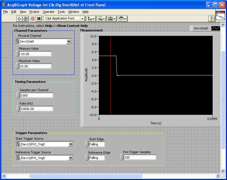
PXI-4461: Acq & graph tension-Int Clk - dig Start & Ref .vi
Samples per channel = 1000
Rate (Hz) = 10000.00
Start the trigger Source = / [name of the instrument DAQmx] / PXI_Trig0
Onboard start = fall
Reference Source Trigger = DAQmx Device Name] / PXI_Trig0
Reference edge = fall
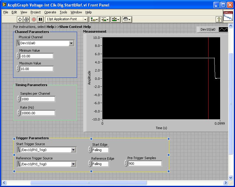
Trigger samples = Variable (100, 500, 900)
PXI-2567: Switch Scaning-SW Trigger.vi
Advance the output terminal full = / [name of the instrument DAQmx] / PXI_Trig0
Scan list = / [name of the instrument DAQmx] / ch0-> com0.
Scan list = / [name of the instrument DAQmx] / ch1-> com1;
Hardware configuration:
The PXI-2567 module controls an external relay that switches between the voltage of 5 V on ch0 and ch1 0 V.
The PXI-4461 connects to the COM of the external relay and therefore reads 5V when ch0 is connected; 0 v when ch1 is connected.
Procedure: The above examples are used in the following procedure.
1. run the PXI-4461 VI. A start trigger (falling edge) is necessary to start collecting samples before firing.
2. launch the module, PXI - 2567 VI. When ch0 is initially (and immediately) on com0, a trigger is sent to PXI_Trig0. The PXI-4461 will begin to acquire samples before firing.
3. - click on the "Connect to the next" button on the front of the PXI - 2567 VI module. This sends a trigger to entry software for the PXI-2567 module and the transitions of the scan for ch1-> com1 list. Once the PXI-2567 module remains (debounced), advanced complete relaxation is sent on PXI_Trig0 for the PXI-4461. The PXI-4461 will begin to acquire samples after outbreak.
Note: Instead of the trigger of the software entry, an external input trigger can be used (e.g. PXI_Trig1).
Results:
> Before instant release of samples = 100
Delay is caused by the time of actuation of external relay.
> Before instant release of samples = 500
Delay is caused by the time of actuation of external relay.
> Before instant release of samples = 900
Delay is caused by the time of actuation of external relay.
I hope that the attached screws and the explanation above helps you and/or other customers who have this problem.
Best regards
Chad Erickson
Switch Product Support Engineer
NOR - USA
-
PowerConnect 6200 series interoperability with 3Com Switch 5500.
Hi all
We offer to our customer Dell PowerConnect 6224 and 6248 as they are expanding their network.
Their existing network is 3Com Switch 5500 and the main switch is 5500G - EI. Of course, on their network, they have mutiple VLAN and switch 5500G - EI core will make the VIRTUAL LAN routing.
I would like to know, is it questions about interoperability between 3Com Switch 5500 and Dell PowerConnect 6200 Series, especially on the VLAN routing?
Know your opinion.
Thank you and best regards,
Syed.
I'm not aware of any questions that you would see with the use of these switches together. On switches 62xx you set them VLAN, and then set the connection of 3Com in general or Trunk mode, allowing the VLANS on the connection.
Create a VLAN
Console (config) # vlan database
VLAN console(config-VLAN) # 2
VLAN console(config-VLAN) # 3
VLAN console(config-VLAN) # 4
output console(config-VLAN) #.
Configure the interface in Trunk mode and allow for VLAN through it.
console switchport mode trunk #.
console # permit trunk switchport vlan add 2,3,4 tag
You may need to set a static route on the 62xx switch so the traffic on the next hop.
Console (config) # ip route 172.16.0.0 255.255.0.0 10.0.0.2
Here are a few good white papers to look over. Not all of them concern the 62xx switch, but the information is always good.
www.Dell.com/.../app_note_38.pdf
www.Dell.com/.../app_note_2.pdf
www.Dell.com/.../pwcnt_link_aggregation.pdf
www.Dell.com/.../pwcnt_VLAN_interoperability.pdf
www.Dell.com/.../app_note_4.pdf
Thank you.
-
For the test I used 2 switch this name 'ESW X' and 'Y ESW '.
I have 2 network that I named "Network A" and "Network B".
I build a VLAN 2 for each network named Vlan 2 for network and Vlan 3 to network B, I do not use Vlan 1 because it is the default Vlan
Configuration ESW X:
port e1: access on UNTTAGGED Vlan 2 PORT
port E2: access on UNTTAGGED Vlan 2 PORT
E3 port: PORT of ACCESS on UNTTAGGED Vlan 3
E4 port: PORT of ACCESS on UNTTAGGED Vlan 3
G3 port: with 1 (default) UNTTAGGED Vlan TRUNK PORT and Vlan tagged WITH 2 and 3 to Vlan
Configuration ESW Y:
port e1: access on UNTTAGGED Vlan 2 PORT
port E2: access on UNTTAGGED Vlan 2 PORT
E3 port: PORT of ACCESS on UNTTAGGED Vlan 3
E4 port: PORT of ACCESS on UNTTAGGED Vlan 3
G3 port: with 1 (default) UNTTAGGED Vlan TRUNK PORT and Vlan tagged WITH 2 and 3 to Vlan
I use for the test computer 2 with the same class IP address.
Test result:
Communication between ESW X e1 and e2 x ESW => OK
Communication between ESW X e3 and e4 x ESW => OK
Communication between ESW e1 and e2 ESW Y => OK
Communication between ESW e3 and e4 ESW Y => OK
Communication between e1 ESW X and Y of the ESW e1 or e2-online NOK
Communication between e2 ESW X and Y of the ESW e1 or e2-online NOK
Communication between e3 ESW X and Y of the ESW e3 or e4-online NOK
Communication between e4 ESW X and Y of the ESW e3 or e4-online NOK
Each Vlan cannot communicate with the switch, I think they have a problem in my configuration of vlan / port, can you help me.
Hi, Thibaud,.
Thank you for the purchase of the ESW switches.
Just out of curiosity, you are using the latest firmware on your version of switch ESW 2.1.19
But of course, you seem like you have a great understanding of Tagged and VLAN no tagged of you ad description... great stuff.
I just tried your configuration, I can communicate between ESW540 - 24 p-switch and a SF300 - 48p.
Sorry, I don't have two switches handy ESW. But it doesn't matter. Standards based Ethernet is I hope that some standards based on ethernet
My configuration of vlan below for my ESW540 - 24 p and it works very well.
I plugged just ports of the switch 24 between the two switches together, that's why the 24 port is labeled in each of the screenshots below.
I really really doubt you would have a problem, unless there is something fundimental or basic you did for example do not save the configuration running on the boot configuration. Obviously do not save the configuration before a power down will kill the configuration.
(saved your configuration in each switch)


Here is a copy of a part of my switch running configuration, which were a result of me playing with the ESW configuration utility.
(Note that my switch has all Gigabit ethernet ports ;)
serial interface ethernet g(1-2)
switchport vlan trunk native 2
output
interface ethernet g24
switchport trunk allowed vlan add 2
output
serial interface ethernet g(3-4)
switchport vlan trunk native 3
output
interface ethernet g24
switchport trunk allowed vlan add 3
output
If you still have questions, here's what URL to the Small Business Support Center contact, perhaps a new set of eyes can spot the problem.
http://www.Cisco.com/en/us/support/tsd_cisco_small_business_support_center_contacts.html
Best regards, Dave
-
Digital output with NOR-9401 in cDAQ-9174
Hello
I have a cDAQ-9174 with an e/s digital NOR-9401 module. Now I want to output Digital signals on line0:3
$line0: Boolean 1 time = 10ms
Line1: Boolean variable 1 time = 20ms
row2: Boolean variable 1 time = 30ms
line 3:20 pulses (period = 250us, duty ratio = 0.5) after a time = 40ms
the value of line0:3 must be Boolean 0 after 45ms
Can someone let me know what I need to work to solve this please?
Thank you all for your help.
Concerning
Bing
Thank you Christian for your quick replay.
I have some experience in programming of microcontroller with C. I learned LABVIEW for about 1 month and followed a lot of demons in line and tutorials. I know that nodes DAQmx Data Acquisition screws and fundamental property.
As I said at the beginning on the $line0, lin1and line2, they serve to control the relay in my circuit. 10ms could be controlled with the OS clock. Pulse of line3 series is used for IGBT gate signals, which is the critical moment. I want to use the clock machine to accurately control line 3 and synchronize at the same time the pulse with analog inputs from an another two NI9206 modules in the same cDAQ chassis.
I just want to know more on the digital line demand signal relay output and a correlation between the line of analog input-synchronized finished pulse output. Waveform diagram is locked.
Thank you.
Bing
-
Hey Cisco experts!
I have a small question, I'm sure you can answer for me. I have installation of the Israeli army for the clients that I questioned how they are physically connected. Connection to the MDF is ok because they use their ports of 10 GB on fiber optics. The question I have is if there are multiple switches in the Israeli army should they be connected to each other using their 10 GB ports from A to B and C and then also to connecting A to C on switch ports? I think it's can cause a loop but wanted expert advice.
Thank you
Hello
Yes, when you have multiple MDF switches, connect together to provide redundancy of the network. Of course if you connect to layer-2 switches together, you must run stp or use some other technologies like stack to make it look all MDF has a switch. There are also VSS for the 6500 that offer the same advantages as the stacking on the 3750 series. In this way, your don't have to use STP.
HTH
-
Can somone tell me if it is necessary to join two switches together during the definition of redundant paths and so why is this need to be?
To give an example, I have a box of ESXi 3.5 with 2 uplinks were team together for iSCSI software storage. On this team, I have a cable going to a switch and another cable from another switch. My san also has the same configuration for the grouping.
The switches must be connected togther and if so why?
Thank you
Tony
Typical connecting two switches together aims to make them behave like a single large switch and increase redundancy.
Charles nights, VCP
If you have found this or other useful information, please consider awarding points to 'Correct' or 'useful '.
-
Connect a PCI-6521 and a PCI-4065 DMM
Hello
I would like to know if I can use that digital relay is issued by a PCI-6521 to switch between the 4 lines in which I have to measure resistance using a PCI-4065 DMM.
I´d would like to know if West any question if I log out of the PCI-6521 together four terminals (to GND) and then I connect the other 4 sides of each output at each of the points where I need to measure the resistance. So when I measure the R1 resistance, for example I have activate the respective relay output and I disable all other 3 exits. And then I read the resistance with the PCI-4065. And so now... with the other 3 resistances. I´d would like to know if West any connection problem of the PCI-6521 with the entry of the PCI-4065 DMM outputs.
Thank you!
Hi MariMS;
You can use the configuration that you explain, but a 4-wire or 2-wire configurations are recommended depending on the application, for example, if the resistance you meassuring is greater than 100 kOhms, you can use a configuration 2 son, but if it is lower, you must use configuration 4 sons. The following document has a more detailed explanation about them.
http://zone.NI.com/DevZone/CDA/tut/p/ID/3610
I hope the information is useful.
Good luck
Francisco Arellano
-
Management control of the engine with proximity sensors
I have two prox switches and two relays that I can control in labview manually, however I was unable to produce the needed code to "lock" or the relay that prox has been activated. The application is very simple, I have a linear actuator that I run at the end of the race until it activates the switch prox "scope". At this point, I want to activate the second relay to reverse the direction of the motor until it activates the "home" prox switch
I know that someone will take about two seconds to bust the code but I was failing for about 2 days on this subject. Any help would be appreciated.
Thank you.
Try this. Proximity detectors and the relay outputs are simulated. You will need to replace those with your digital inputs and digital outputs.
In the last image, it is a small flat sequence with the button stop running to ensure that all relays are extinguished in the case where the program Stop button by wire a fake to the local variable. Excerpts from VI transformed into nodes of property with controls to control wired in them reference.


Maybe you are looking for
-
Mac mini el capitan "sleep next failure experienced a problem.
I just bought a new mac mini with El Capitan installed, I transferred all my software and back up files on the old Mac mini via a time machine. Since then I've been finding this message once the computer has been idle: "sleep next failure experienced
-
Reset E-mail - HELP blackBerry smartphones!
Recently, my email address has been compromised on @rogers.com. I changed my password through my laptop which in turn prevented the emails from my blackberry... When I get to send parameters on the blackberry and type user name and password, he conti
-
Phone calls from showing in messages blackBerry Smartphones
It's maybe a stupid question, but I all the calls shown in the list of messages. How can I get rid of these?
-
Media Player is up-to-date and copies of all the music files added, I have 5 copies now
I can't find any way to stop this update and addition of copies of everything in my music files. I delete thecop ies and they keep coming back. There is no settings I can find to solve this problem, please help. Diane
-
I ran the upgrade wizard and got through the entire process and paid the 39.99 and then I got an error saying that it was unable to process the receipt. and I couldn't do anything else but to close the screen. I was charge the $39.99 + Tax (it's on m