scanning voltage
Hello, I have the tension between say (5-volts to 5 volts) to scan as
between 01:55 to step size of 1 and between-2 and 2 to a 0.5 step size, then a 1 beyond 2 step size.
01:58 range may change. (user input)
can someone help me find a way to do it.
concerning
Debi
Tags: NI Software
Similar Questions
-
scanning voltage and current measurement for Keithley 2400
Dear all
Hello
can someone help me?
Despite days nearlly10 I am option to find any program LabVIEW 2010 for sweeping the voltage and measure current who works with RS-232, I have a end not have nothing exept examples read single and multiple data. I tried to SmartData labview and changed a few prorgram gpib to RS - 232, but I couldn't.
In another attempt to find a good VI "votltage scanning and current measurement" that work with RS-232 in labview 5.1.1. I have converted in 2008, but it takes old driver (ke24xx.dll) and do not work in my labview 2010 and I could ' t find older driver.
My thesis project was halted in those 10 days, and I couldn't do anything for our keithley.
Please helpe...
in the following, I have attached these files:
1.-first, what voltage scan that works with GPIB
2 - Vi that I change the gpib for visa (rs232) port that I don't know why it doesn't work.
3. it is Vi related to the "sweeping and current measurement votltage" that works with the RS-232, but it takes old dirver so I can't use it.
4-slot-VI necessary for the implementation of program 3 (but there is no driver for these subVIs) was attached to the reply message of this post
If any body has this program ("scan votltage and current measurement" running rs - 232) please send to me
Thanks in advance.
None of you attached the screws are the driver OR you spoke. There is no conversion required for this driver.
-
PCI6251: How to reduce widely AO size FIFO or Disable AO FIFO in AO HW timed DMA operation?
I took aoex5 as a basis for the generation of signals timing hw AO0 DMA and it works well in my setup. At the same time two signals which depend on AO0 are measured to AI0/AI1 by hw-timed-DMA mode maximum rate (500 ksps / s) and it works as well.
My goal is to apply a positive feedback mathematically AI1 to AO0 nationwide, and the easy way would be to change the values in the channel DMA AO AO rate on the fly, by reading the latest channel DMA AI values. The processor speed and the DMA space would be quite sufficient. The problem is that the CED are charged by means of a FIFO buffer that has a size of 8192 samples for my Board, and so to change a value in the buffer DMA would have no effect on the output DAC.
I tried to simply disable the buffer FIFO of AO by setting AO_FIFO_Enable to 0, but it disabled the generation of signals AO together. Is there a way to disable AO FIFO and leave the DAC values directly from the buffer DMA? Or can I reduce the size of the FIFO AO programmatically to a minimum number of samples (2-16)? I could survive with a little latency induced by a small FIFO buffer, because I can compensate for this by changing the rate AO on the fly as well.
I know, I use timed by the sw operations to achieve the goal, but I assume that AO DMA without FIFO operation would give me a lower latency of feedback.
Thank you very much in advance for any helpful ideas.
Best regards
Rolf
Hello Joe!
I decided to start my experiments with the generation of signals AO0 clocked by sw.
In order to test I put AI_Bypass_Cal_Sel_Pos-7 and AO_Bypass_AO_Cal_Sel to 0, while the generated signal is directly available on AI0. I was programmed to the maximum rate of dual channel (500 ksps / s) in a linear DMA buffer of 128 MB. To AO, I programmed a triangle (ramp-up/down) for a period of 2 V which is represented by 12975 AO samples.
A tight loop software added an average across the last 4 Readings found in the DMA buffer to the AO value at the next exit, and once the LSB of the gross sample of AO changes, it is written to the DAC by Board-> DAC_Direct_Data [0] .writeRegister (Uc).
I did tests with different speeds of scanning voltage from 0,1 up to 250 V/s. The AO to 250 V/s sampling rate was 1.6 MECH. / s. The deviation of the curve at the higher rate to the lowest rate is only 0.1%.
Attached to this message you will find a diagram showing the magnification of the curves around the tip of the triangle. The Green curves taken at 100 and 250 V/s. Red to yellow to 0.1, 1 and 10 V/s. There are very low phase shift of 0.1% to scan rate of very hight perhaps due to the latency of your comments.
Honestly 1.6 MECH. / s mode AO NI by sw including the algorithm of feedback far exceeds the expectations and I must admit, I am perfectly satisfied with this result. Sorry, Joe, but with that, I lost the inspiration to try out your suggestions, reducing the size of AO DMA buffer and change the FIFO AO mode. Anyway, thanks a lot for your answers.
Best regards
Rolf
-
Change the frequency AO AO DC voltage scanning scan?
Hi all
I am very new to labview, but find the forums and examples extremely helpful. I probably spend 50 + hours to familiarize myself with tutorials and general information, but I am at a point where I need your help.
I'm unable to change the example "AO frequency sweep" found here (see custom_sweep_1.VI) to allow me to sweep the voltage. My instinct is that I don't need of the ' waveform buffer generation VI ' and that I should be able to remove the associated entries since I'm only interested in a sweep of DC voltage. It is also called create_log_frequencies.VI, and I'm fairly certain that I can use it as written and simply change "frequency", "tension". My work of the custom_sweep_1 changes are attached as custom_sweep_Voltage.
The problems I am having with the edition of custom_sweep_1 are:
(1) I don't think I understand very well how or if the parameters associated with waveform buffer generation VI relate to a sweep of DC voltage.
(2) an extension of 1): the loop depends on the samples and Cycles by buffer and I don't know how / whether to replace these values
(3) the .VI DAQmx Timing (sample clock) receives its sampling frequency of output waveform buffer generation VI, but I think I can use 1/scan time to replace this (?)
(4) the DAQmx Write.VI gets waveform buffer generation data, but if I can get around this VI and AO tension of wire directly to write DAQmx then I think I can use minimum voltage as my entry of data (?)
(5) after the implementation of these changes, the custom_sweep_Voltage runs, but I get error 200609:
"The possible reasons:
Generation cannot be started because the size of the selected buffer is too small.
Increase the size of the buffer.
Choose the size of the buffer: 1
Minimum required buffer size: 2"Task name: _unnamedTask<3A>"
I also note that I tried other ways to create the sweep of voltage DC VI:
(1) I have tried change the tracer IV example (found here), but it's much more confused than change the frequency sweep.
( This tutorial and sample 2) block diagram looks like straighforward, and I also work on understanding what Assistants DAQ 1,2, 3.
Any return would be great. I think it is clear that at the very least, my poor understanding of 'buffer' is if the cause of my confusion about the change of frequency scan, please do not hesitate to share any information you have.
Thank you very much for the help,
-Esperanza
Additional information on my project/progress using labview follows below:
My final goal is to determine whether or not the resistivity of a sample of organic driver changes over time. For this I want to compose a VI simultaneously sweeping the output voltage DC-5 to 5V periodically during 24 hours and measure the voltage drops to my load resistance (to determine the current in the circuit) and the sample. I use a USB 6259 DAQmx and that you have correctly configured my circuit. I work two screws that I created with the DAQ assistant and by changing some of the examples, I found online. Output voltage (of an AO) but I have to manually select the voltage value. The second reads voltages in three samples of interest and writes the data to a PDM file. If you've read this extreme sensation and still make a contribution, my next goal after finding how to sweep the voltage is to combine this with my VI measure VI. I think it will be relatively simple, but still, I rejoice in all your comments!
I solved this problem. I have changed my approach to be similar to the last link in my post. AO frequency scan approach is much more complicated that I need. Thanks for the help.
-Esperanza
-
Write error in scan-1073807339 voltage Keithley 2400 to VISA, GPIB
I'm working on a VI that sweeps the voltage across multiple PV devices, all in two States (light and dark). I use the SCPI and a GPIB commands to send scan to the Keithely and store it in a memory slot. So I ask this field using a sub - VI for each device in the two States. The first State (light) still works fine. VISA writing successfully sends the script to the Keithly and VISA read records of information successfully. But when the VI tries to run the same Subvi in the 2nd State (dark), I get the error of delay of 1073807339 waiting.
Ways, I tried to solve this problem:
-adjustment of the byte for VISA read rate (at one point given, I was getting the error on VISA read, not write)
-adjust the setting of time-out of VISA by the suggestion of Web site of nor
-loading of the script on the keithley each time for each scan
In addition,
I collect 100 points of data with each scan-05V to 2V.
Whenever I get this error in order to get anything to connect once again, I have to close out of labview and could power off, power and reconnect the keithly
Help, please. This could be a problem with my GPIB device? or my Keithley 2400?
Thank you
I tried all the solutions, but none of them helped. However, I have finally solved the problem on my own. The issue was that the VISA session was not properly closed / emptied after each scan. To resolve this issue, I added VISA close at the end of each scan and clear VISA before each scan.
-
Scan USB 4431 DC analog output voltage
Hi all
I have NI USB 4431 Analyzer of dynamic signals. I want to generate constant tension on the port AO0 of this material. I tried to use the Gen Update.vi blood sample, but it is said that only updated the HW Timed mode cannot be used with this equipment. When I use the Test of MAX Panel, I can generate a constant tension.
How can I make it happen in Labview? Can someone help me?
The USB-4431 can be used to generate a voltage, but to do this, you actually create a timed task equipment. This is because it uses a DAC delta-sigma, which must be clocked to produce output. To do this, I would recommend that you set up the device to perform a finite generation. The data you write are just the DC value that you want to copy, repeated. Then you want to define the area of OCCUPANCY. Property of IdleOutputBehavior. In LabVIEW, this is located in DAQmxChannel-> outputs Analog-> General Properties-> output Configuration. In the C API, you would call DAQmxSetAOIdleOutputBehavior to DAQmx_Val_MaintainExistingValue.
To summarize:
(1) create output over task
(2) configure the IdleOutputBehavior property
(3) write the data (value of DC, repeated)
(4) to start the task.
This should lead to the value of the DC output.
Hope that helps,
Dan
-
Measure the voltage and the temperature simultaneously with PCI-6281
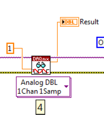
Measure the voltage and the temperature at the same time at the same time. However, when I put the voltage and temperature in a loop, the acquisition of voltage is significantly delayed. When I put the voltage and temperature in two different loop, none of them works. There is an example in aid of Labview as shown. This structure works fairly quickly? In addition, how a volgate get and temperature Analog DBL 1Chan 1Samp? I check the exported excel, the first column is 0, 1 the second column contains the value of the voltage, temperature value. I wonder how can I get these two values for each scan.
,
Assuming that the DAQ cards can handle it, you can set an analog trigger for the channel of the tension. Then you just X samples to get your 100us data value. Keep the last sample.
-
How to synchronize the start of IT and relaxation the Scan list (DAQmx Switch)
Hello
I want to measure samples of N to the AI0 of Council NI PXI 4461. The measurement starts on a rising edge of a digital triggering provided to the PFI0 of the same Board. The measure is configured with samples of N/2 pretrigged. So far, everything is under control...
Using an NI PXI 2567 Board, the signal applied at the entrance the 4461 (AI0) switches between a V2 and V1 signal. I would like to synchronize the switch between the two signals with the trigger signal applied to the input of the PFI0 Governing Council 4461. In order to obtain samples of N/2 of V1 and V2 samples N/2. Synchronization of 1 to 5 ms would suffice!
My question is how to synchronize the start of acquisition of AI pretrigged of 4461 with the switch control given by the Council of 2567?
Thank you in advance for your help...
PS: the configuration of the system is:
-LabView 8.5
-Chassis PXI-1044
PXI-4461 on slot 2
Module 4-slot PXI-2567
Hi Frederic,.
I came back to this recently and used the following examples to run the desired synchronization.
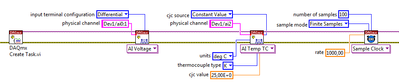
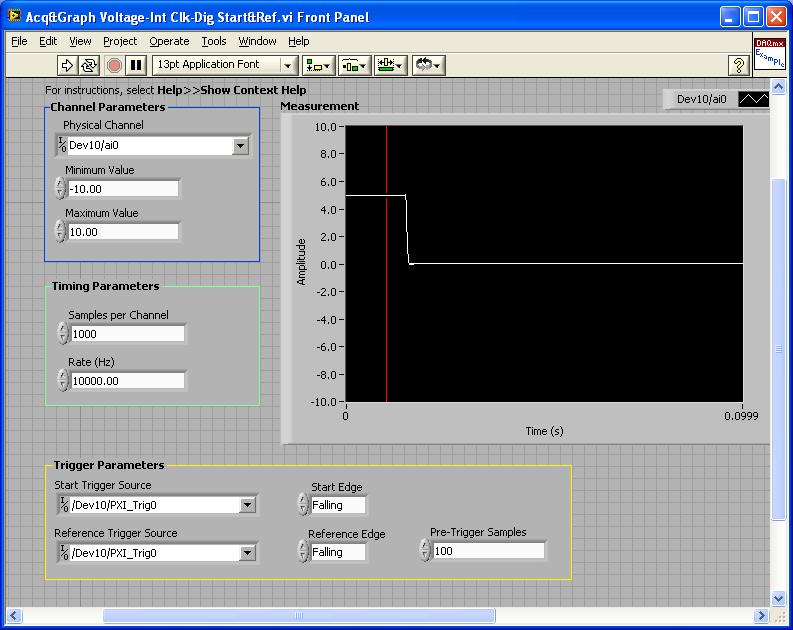
PXI-4461: Acq & graph tension-Int Clk - dig Start & Ref .vi
Samples per channel = 1000
Rate (Hz) = 10000.00
Start the trigger Source = / [name of the instrument DAQmx] / PXI_Trig0
Onboard start = fall
Reference Source Trigger = DAQmx Device Name] / PXI_Trig0
Reference edge = fall
Trigger samples = Variable (100, 500, 900)
PXI-2567: Switch Scaning-SW Trigger.vi
Advance the output terminal full = / [name of the instrument DAQmx] / PXI_Trig0
Scan list = / [name of the instrument DAQmx] / ch0-> com0.
Scan list = / [name of the instrument DAQmx] / ch1-> com1;
Hardware configuration:
The PXI-2567 module controls an external relay that switches between the voltage of 5 V on ch0 and ch1 0 V.
The PXI-4461 connects to the COM of the external relay and therefore reads 5V when ch0 is connected; 0 v when ch1 is connected.
Procedure: The above examples are used in the following procedure.
1. run the PXI-4461 VI. A start trigger (falling edge) is necessary to start collecting samples before firing.
2. launch the module, PXI - 2567 VI. When ch0 is initially (and immediately) on com0, a trigger is sent to PXI_Trig0. The PXI-4461 will begin to acquire samples before firing.
3. - click on the "Connect to the next" button on the front of the PXI - 2567 VI module. This sends a trigger to entry software for the PXI-2567 module and the transitions of the scan for ch1-> com1 list. Once the PXI-2567 module remains (debounced), advanced complete relaxation is sent on PXI_Trig0 for the PXI-4461. The PXI-4461 will begin to acquire samples after outbreak.
Note: Instead of the trigger of the software entry, an external input trigger can be used (e.g. PXI_Trig1).
Results:
> Before instant release of samples = 100
Delay is caused by the time of actuation of external relay.
> Before instant release of samples = 500
Delay is caused by the time of actuation of external relay.
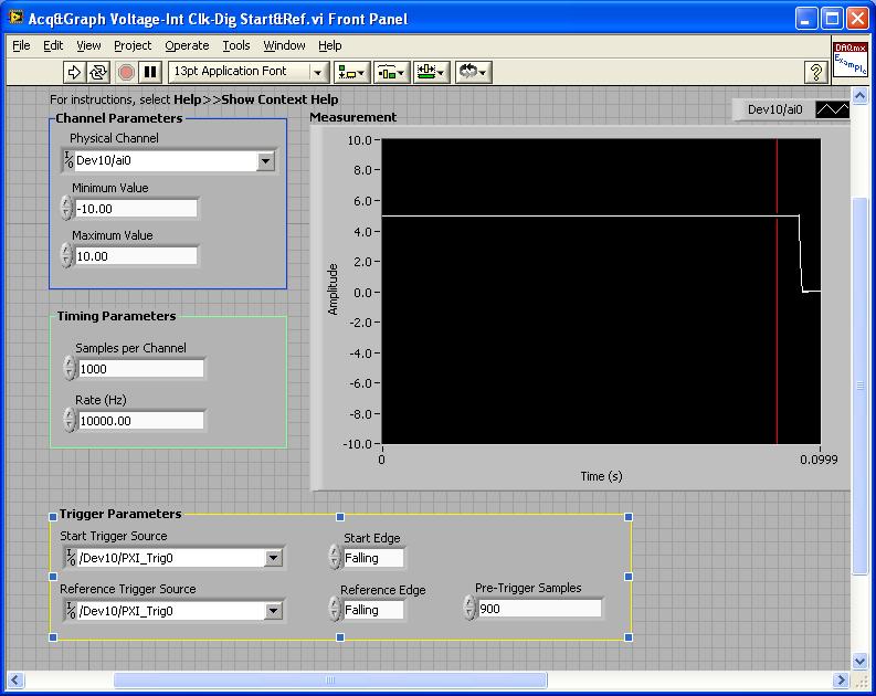
> Before instant release of samples = 900
Delay is caused by the time of actuation of external relay.
I hope that the attached screws and the explanation above helps you and/or other customers who have this problem.
Best regards
Chad Erickson
Switch Product Support Engineer
NOR - USA
-
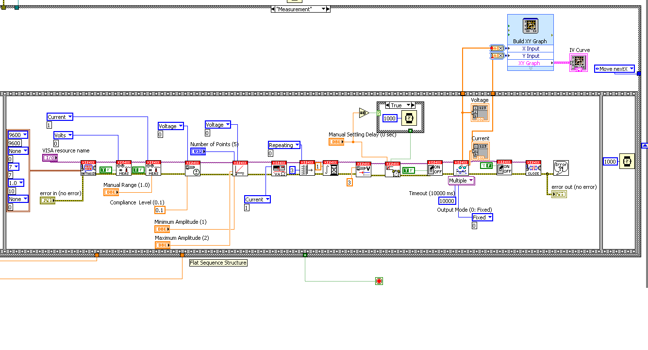
sweep the voltage keithley 2400
Hi friends,
I ve made a small program (reusing an I found in the web) to generate a curve using Keithley 2400. I want to sweep the voltage of 1V-1 using for example 10 points and get the current in a graph and a table.
However, something is not because I have only (not yet correct) measure and no image in the chart and no data in the table.
Could someone advise me here, please?
Any help is welcome!
Thank you
Hi LabVIEWers,
I ve you have a problem receiving data from Keithley 2400.
I m using a distributed (attached) Keithley LabVIEW example and suddenly it does not work. When I run the program it sends the information to the Keithley and a scan is performed. The problem is when the scan is done, no data back to the program so I can't save all data or see any result in a chart or table.
I ve tried to debbug program using the option to highlight and it is for me that the data are intended to the curve, but I have nothing (just #0 in the output of the Sub - VI last before the graph).
The strange thing is that this program works so far, no idea what can be the problem?
Thank you very much!!
-
mode scan interface - 805 error
Hello
I am a beginner system Compact RIO. The on I have a few questions scan mode interface.
The only plug-in hardware is
The cRIO-9012 controller and chassis integrated cRIO-9101
a map AI 9205
a card DIO 9401
I would like to use the scan interface mode to understand the functioning of the cards, the in FPGA interface mode, it takes time for the compilation.
The chassis does not support the interface mode scan, so I set up 2 cards variables individually using the I/O. Then I create the VI United Nations simply to read the voltage level of the card HAVE. I get an error - 805: source of synchronization, synchronize with the scan engine.
I also checked in MAX, scan of OR soft the engine is installed.
Could someone tell me this problem?
Thanks in advance.
Lily
-
Why me disables the user interface click on another button, while it performs a scan?
Hello
When I run the user interface and click on a button that is sweeping the voltage for a period of time, I can't press any other button that sits on my Panel, lets say the Abort button that would prevent the action.
So when I take the data and I realize that I should stop him before he finishes the scan, I can't and it's a really bad drawback.
How can I improve this problem?
Thank you
Hi m.s.taba,
It seems to me that your code runs the function leave but does not exit the loop you are, then the program stops at the end of the loop.
To avoid this, you can:
- use a global variable to the time your long recall and the recall of quit smoking
- Call ProcessSytemEvents in the loop
- reminder for the button leave defines the global variable
- inside the loop, immediately after ProcessSystemEvents, you should test the value of the variable, and if the value you must break out of the loop
- only after the exit of the loop, you can complete your program
-
How to read any voltage (0 - 10v) with NI 9421
Hi I am a beginner in cRIO. Play with the cRIO-9012, NI9421. There is a sample program in Labview named 'NOR 94xx entry - getting started - scan Mode'. This is a basic program just to show the State of the LED, when there is something in DIO1. I have implimented the program by changing the chasis of the target. To see how it works, I used a calibrator to send some tension to NI9421. The led in fact to 8v. My question is how can I turned it on even in low voltage 2v, 3v and 5v. Someone help me please what settings I need to change. ? I am attaching the screenshots of the program and the labview example file.
If you look at the datasheet for the 9421, a logical 24V digital input module. It states that a shutdown state is 5V or less and one State on East 11 - 30V. Anything between the two should be considered unstable.
You cannot simply choose the logical level for the input module.
-
NOR-6008 selection file Matlab .m voltage range
Hi, I need to select a range of power such as - 1V to + 1V file .m in MATLAB to acquire data of acquisition of data NOR-6008.
I appreciate if someone can send me a code example.
The system works very well and I can control successfully the sampling frequency, but not the voltage range.
Concerning
Hello
The two alternatives are equivalent, option 2 is how to get to a channel if you had not registered to a variable when it is created.
When you say that it doesn't work, do you have an error message?
I just tried it on my machine with an NI USB-6008 with 4 channels and the range set to-1 [1] on one of these channels:
> s = daq.createSession('ni')
s =.
Session data using National Instruments hardware acquisition:
Will work for 1 second (1000 scans) to 1,000 scans/second.
Some channels have been added.> s.addAnalogInputChannel ('dev2', 0:3, "voltage")
years =
Session data using National Instruments hardware acquisition:
Will work for 1 second (1000 scans) to 1,000 scans/second.
Number of channels: 4
index of Type channel MeasurementType range nom_peripherique
----- ---- ------ ------- --------------- ---------------- ----
1 THE Dev2 ai0 (Diff) voltage-20 to + 20 v
2 THE Dev2 ai1 voltage (Diff)-20 to + 20 v
3 THE Dev2 ai2 voltage (Diff)-20 to + 20 v
4 THE Dev2 ai3 voltage (Diff)-20 to + 20 v> s.Channels (2). Range = [1-1]
s =.
Session data using National Instruments hardware acquisition:
Will work for 1 second (1000 scans) to 1,000 scans/second.
Number of channels: 4
index of Type channel MeasurementType range nom_peripherique
----- ---- ------ ------- --------------- ------------------ ----
1 THE Dev2 ai0 (Diff) voltage-20 to + 20 v
2 THE Dev2 ai1 voltage (Diff) - 1.0 to + 1.0 v
3 THE Dev2 ai2 voltage (Diff)-20 to + 20 v
4 THE Dev2 ai3 voltage (Diff)-20 to + 20 v
Properties, methods, events> s.inputSingleScan
years =
-0.0034 0.0008 0,0059 0.0012
Wael Bruno
The MathWorks
-
How to set the time difference between each data when using keithley 2400 scanning
Hello friends,
I use scanning Keithley vi the extent of SCANNING and acquire vi. I want to measure the voltage for each step and a pause between each two data, so I need a delay between each I step.
I'm a starter to use Labview, thank you very much for your answers.
Perry
As Dennis says, if you use the built-in scan function, you will need to consult the manual. See Section 10-16 (this is page 10 of article 16, only paragraphs not but 10, 16) for the manual Keithley 2400.
The Keithley 24xx series has a speed of measurement in units called PLC (Power Line Cycles). The default speed is 1PLC, which means a measure is taken with each cycle of line 1 power supply or 1/60th of a second (16.67ms). 24XX can range from 0.01 PLC (all 0.16ms) 10 PLC (all 166.6ms). The faster you measure, the less accuracy you get.
To programmatically set this value, the command is
 ENSe:CURRent:NPLCyclesENSe:VOLTage:NPLCycles
Depending on what you are sensing and where
is the number of controllers from 0.01 to 10. Another factor that will determine the time between data points is the cycle SDM. These are more complicated, look at your Keithley manual for more information. Look at article 6 and article 11 for more information.
Note:
PLC times are based on a cycle of 60 Hz US.
-
Agilent U2722A linear voltage ramp
I am currently writing a LABVIEW VI to interface with an Agilent U2722A. I want to measure current constantly while maximum increase of voltage of 0V to a defined use specifying the step size and no time (a linear scan of tension).
I downloaded the driver for this device which also includes an example used for output and then take action. My first problem is that when I run this unit VI is to expire. I think that this issue MAY have something to do with the entry "triggered the level". Happened to configure voltage channel VI. I have included the example and the voltage setting channel Sub VI.
My lack of understanding for the other SubVIs (which are based on being passed SCPI commands by VISA as strings) also prevents me from making progress. Especially the scan configures and configure trigger screws
Scanner Confgiure takes the values for the number of points and the timestep. I don't know how I'm supposed to make use of this VI. Should I put the values you want, and then use a loop to pass different values to the chain tension set up with each iteration. Also, how is the measured timestep? I need to set up a trigger to measure the time between the points or the scan function takes care of that? I've included the sweep set up VI as the Timestep VI as well.
Looks like that you've got another error in connection with the IO instrument. Here are some references for this error,
-420, "request not COMPLETED;
This error occurs when you addess the instrument to talk and he has nothing to say.
The most likely causes are:
1. do not send a query. You must send a valid request to the instrument before talking to talk to him. This is true even of the instruments of measurement, such as the 2001 model. You can not get a reading from 2001 until you send him a request.
2 send an invalid request. If you sent a request and still get this error, make sure that the instrument treats the query without error. For example, send a bad request that generates an error - 113, "Undefined header" and then treat the instrument to speak will generate an error-420, "Request not COMPLETED" as well.
3 query invalid due to an invalid command.
Currently I do not have an instrumetn in hand so I can't understand what is exactly what's wrong, but would you mind to paste your code so that we can look into it together?
The most accurate method is absolutely one provided by the material itself. Here is "Interval" in configure Sweep.vi.

Maybe you are looking for
-
I have a T440s running windows 7 with a module mobile 4g of em7345 installed, installing drivers correctly and it recongnises the SIM, but is unable to find the network (on troubleshooting, windows connection suggests that there is no signal, but my
-
All of a sudden unable to connect to a home network on XP
I got the message error «windows cannot configure this wireless connection...» If you want Windows to configure this wireless connection, start the automatic Wireless Configuration Service... see article 871122 on-site Microsoft Knowledge Base web mi
-
Disk Defragmenter missing analyze it to see if it needs it featured
When I open the Disk Defragmenter on my computer vista laptop it does not give me the opportunity to see if my computer needs it as my windows xp desktop.
-
E1550 sees no USB storage drive
I had a Toshiba HDD (1 TB) connected to my E1550. 8 months that the reader has twice had a problem with being able to save/replace the files after he successfully files for a period of time. Given that my storage device was not on the list of "approv
-
BlackBerry software BlackBerry link v1.2.3.23: is this a 64 bit OS
I went to insttall this program and it refers to 32. It is also suitable for a Windows 7 64-bit OS? Thanks for all replies. Ken