simulation of mx DAQ
Buen dia.
me gustaria simular tajetas mio y dio, e visto videos than simulan voltajes y señales pero no explica como, lo quiero are simular sin nada solo external the computadora, usar una fuente o osciloscopio simulados para simular señales entrada y salida
There is a page in either donde puedes descargar todos los driver para equipos NOR, ni.com/drivers. Por aca you dejo el link descarga:
http://www.NI.com/download/NI-ELVISmx-14.0/4801/en/
Saludos y mucho exito con you application.
Tags: NI Software
Similar Questions
-
Hello. I just reinstall Labview 8.2 and I do not see simulation devices in Max MAX is 4.2. All I can see cable RTSI. I used to have simulation devices, but I also installed LAbview 2010 before eval. After the complete reinstalled I can't get it back. I tried several times. When I install new DAQmx (I think than 9.1), it installs simulation devices, but then I lose my vi.lib DAQ - mx directory (don't know why).
Based on the info from NI Labview 7.4 and above should have simulation devices. Any suggestions?
I use Win 7 64 bit.
Thank you
Thank you. I think that we get no warning because 8.2 supported by Vista, and that's probably just enough good pass install Win7.
-
I am trying to create a development machine, where we can test the new code without using our physical hardware. I followed this guide to set up a system of simulation. I get to step 3.2 b, but the device does not appear in the DAQ assistant. MAX, the device self test and gites calibrated successfully, and when I open the test panels, I see some sort of signal. I guess that's a default entry simulated since I didn't that device to look for anything? Note that two devices, I am creating the show upward into the devices section and Interfaces, but that, even after running auto calibrate, automatic Calibration date is not yet specified.
When I try to test the device and create a voltage according to the guide, I can't see a device in the creator of data acquisition task.
Steps 1 and 2 of this guide are of course met. Step 3 is not, but this is not surprising because a simulated device is in device in any case manager. Also, I'm not under RT, so step 4 is satisfied.
Someone at - it ideas?
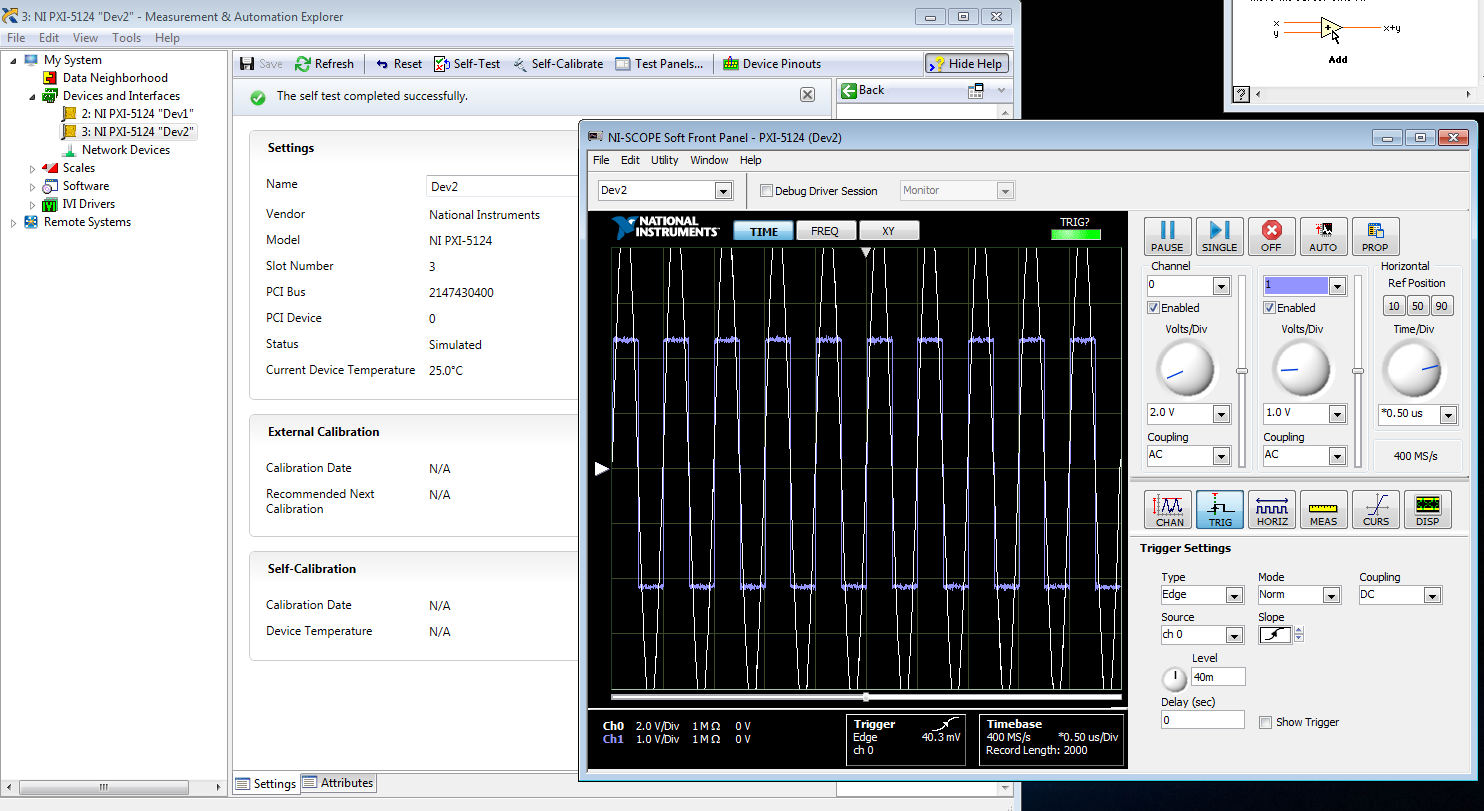
That would be because the PXI-5124 is a digitizer not an analog input device. You must use the NI SCOPE not NOR DAQmx driver
-
Error to the element of the queue with simulated signal, but not with the DAQ hardware
Hello. I get an error code 1 when I run my VI in simulation mode, which is only 3 simulate subvis signal at different frequencies. The block diagram shows jpg file and the probe is after I stop the VI. Note that there is an invalid refnum. I don't know why that is. I am also including the watch of the probe after a few iterations, there is no error on the probe 64 until I stop the VI, and also noted that there have been no queue items. This of course means that I don't get to remove the data in loop 2. An interesting note is that the system works fine when I run the program in data acquisition mode, which is the other case behind the 'simulate signals. " In this case, the only thing is the DAQ assistant and dynamic data of the tunnel cable. Everyone can't see what I could do wrong? Thank you.
Thanks for looking at my post. I thought about it about five minutes ago. I didn't have a timeout on the handeler event, so it was not double check for new items in the queue. I don't know yet why the probe shows showes that items have not put in the queue because they certainly were. Maybe "queue items 0" means that there are no items saved in the queue. ?
Your concern is interesting and deserves a check... I just ran it without registration, and it seems that the release of the case (the default) record structure is just an empty DDT, a placeholder, I guess.
-
How to connect a simulation on the design of controllers to DAQ card?
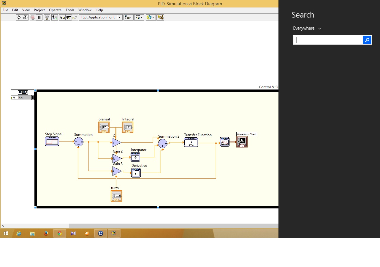
Hi guys... I have problems about control and design on the way to the simulation I just do simulation PID and I can not to connect to the path of the simulation DAQ card in the control design (function)... can someone help me how to connect that?
Ayubi,
First of all, remember that the control and the Simulation has a PID in the Palette "control and Simulation > Controllers.
Then, to connect to a data acquisition card, you must use the DAQmx interface is there to connect. In general, National Instruments recommends allows you to deploy a controller a real-time system, but most likely your Windows computer should be good enough for your application. Please see the example of the expedition (in 2013):
C:\Program Files (x 86) \National Instruments\LabVIEW 2013\examples\Control and Simulation\Simulation\Real - time\DAQmx\RT PXI DAQmx single channel PID.lvproj
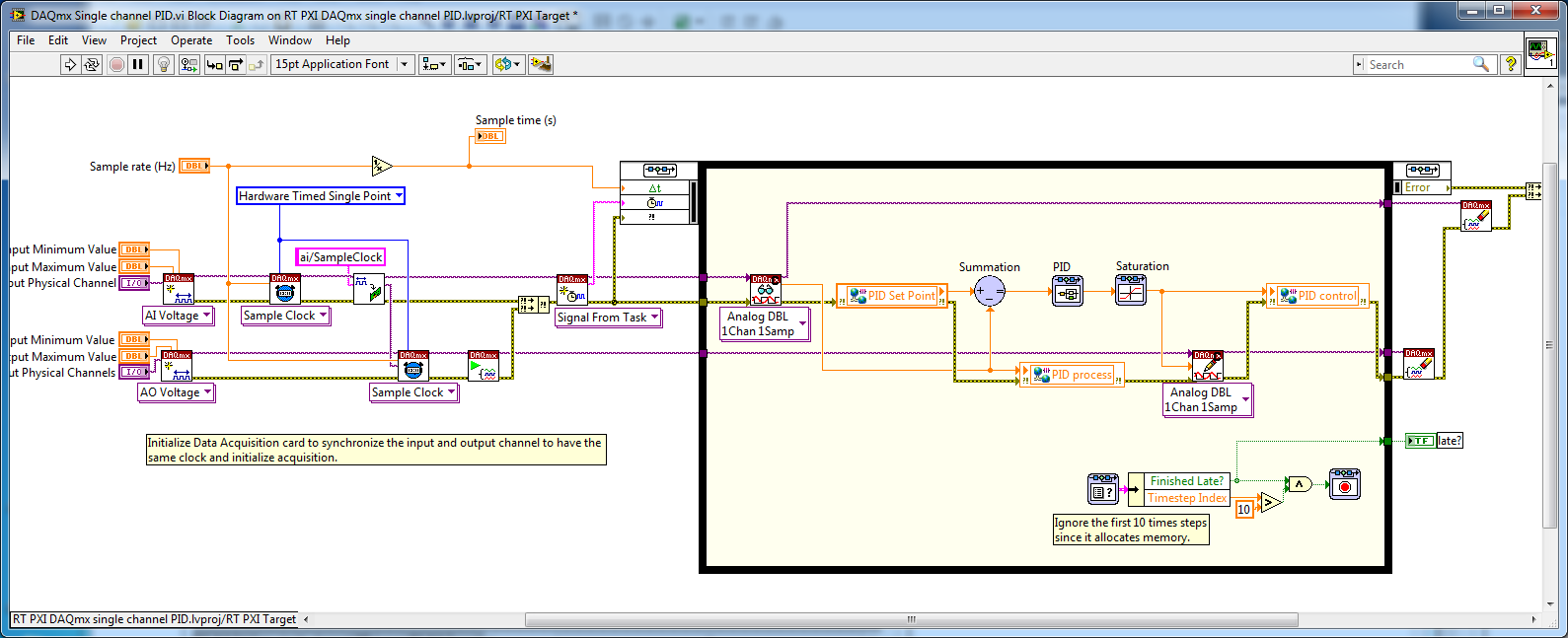
If you don't have a LabVIEW Real - Time (RT), you can simply open the VI:
C:\Program Files (x 86) \National Instruments\LabVIEW 2013\examples\Control and Simulation\Simulation\Real-time\DAQmx\DAQmx single channel PID.vi
Remove the shared Variables in the code and he would be executed on a computer with a DAQ card.
-
Numerical simulation of e/s of FPGA on the development computer - strange results... Help, please
Hello
We ordered a 7851R DAQ card which we
have not yet received and we try to simulate using the
Setting "computer development". However, I can't seem to get the OID
to work properly. In fact simply opening "digital line input and.
Example of output.VI' does not have to wait for results. What happens in the
example of file is just, the indicators flash constantly and are not affected
by controls. Is this a known problem and I just need to wait for my
material or have I done something wrong?Thank you!
Michael
You don't mention what version of LabVIEW you use, but if
you use a LabVIEW 8.6, there should be basically 3 options for
Debug / simulate your VI on the development computer.The
first is to run the VI on the development computer using random
data for FPGA of e/s data. I suspect that this is the option you
currently using and only can be useful if a large number of logic in
your VI depends on the values of the e/s database.The
second option is to use a custom VI which provides FPGA simulation
E/s data. That sounds as if it was what you are looking for. When you
Select this option, you will also get a button you can
Press to create a VI model that can be used to create your custom
VI. If you look at the diagram of the VI model, I think that it
should be relatively simple to understand how to insert your
custom code.The third option is to run the VI on
the host but the use of I/O of the real world. In the latter case, a default value
bitfile is automatically downloaded to the FPGA for you and the data is
transferred from the device by the driver. Of course, you cannot use
This last mode until your material does indeed. I hope this helps. -
DAQ Assistant does not export the values on the scale
Hello all-
Potentially stupid question but here goes: I'm using the DAQ Assistant to read in 4 analog input voltages, continuous sampling acquires data at 10 Hz 1 point, using LabView 12 on a machine with an acquisition of data USB-6341 simulated device (because my office is more comfortable than the lab!). I want to change the first two signals of voltage to temperature and humidity, respectively. I used the «create a new...» "in the 'Custom Scaling' drop-down in the"Voltage configuration"tab for each of these channels, named gave the slope and the intercept at the origin for the respective linear scales and click OK."
When I test the code - and yet once again, I'm not on a machine with a 'real' DAQ system, I use a simulated device, and it seems that NEITHER MAX generates a sine wave of long period with little noise on top for this - I do not get the results on the scale of my 'signal', I get the raw tension. (If you run my code, I will join, the Relative humidity must be between 0 and 100 and temperature-40 to 60, is not 0 to 5, for example.)
So, what happens? Is there some flag or setting that I missed? The scaling only works on voltage data 'real' of a 'real' instrument DAQ, instead of a simulation (which is why I mentioned twice!)? I have to do something in NI MAX as well as Labview?
Thanks for any help you can give.
John Easton
Simulations devices will not respond to custom scale. They are just supposed to allow you to configure your device without errors when you do not have the unit on-site.
"NOR-DAQmx simulated devices create a noisy sine wave to all the entered analog." Simulated data other set-up is not available at this time. »
http://www.NI.com/white-paper/3698/en
They generate a sine with an amplitude equal to half of your specified input range. If you want to work with simulated data that would be more realistic for your application, you could write a VI to generate the data and have a business structure to manage both "simulations" and "real", then you could switch back depending on whether you have access to the material.
I just checked this with a PCI-6254 I install and simulated a PCI-6254.
-
Synchronization of several high at different frequencies of sampling DAQ cards.
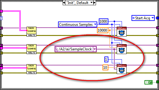
I'm having sync problems 3 high DAQ cards with different sampling frequencies. I use 2 cards PXI-6259 nec 10,000s samples and 1 PXI-6221 Board to interface for my SCXI modules in 10 samples/second. The problem that I discovered is the time related with the waveforms of the NI PXI-6221. When I run the code on a development computer using virtual devices in MAX, it works as expected. When I run the same code on real hardware, the stopwatch turns approximately 25 X faster than normal. I enclose the code and the config that I use.
Any ideas?
Hi NGNN CAD.
First of all, let me say that your code is very nice!
The problem is that you are using the fast sample for the device that is supposed to be slow clock:
Even if you specify the rate as 10 Hz, the clock itself is still at 10 kHz (by specifying the right rate allows the DAQmx driver determine the size of buffer etc and don't actually change your external sample clock speed - however, it changes the rate of the simulated device).
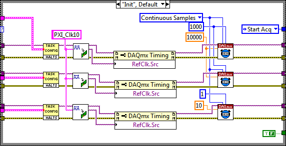
My recommendation to synchronize devices would use the built-in PLL and lock to the reference clock 10 MHz of your PXI chassis. Your devices would always share a trigger to start, but each would generate its own sample clock based on its time base that is locked to 10 MHz reference.
The code should look like this:
I hope this helps, let me know if you have any questions!
Best regards
-
the lack of simulated material
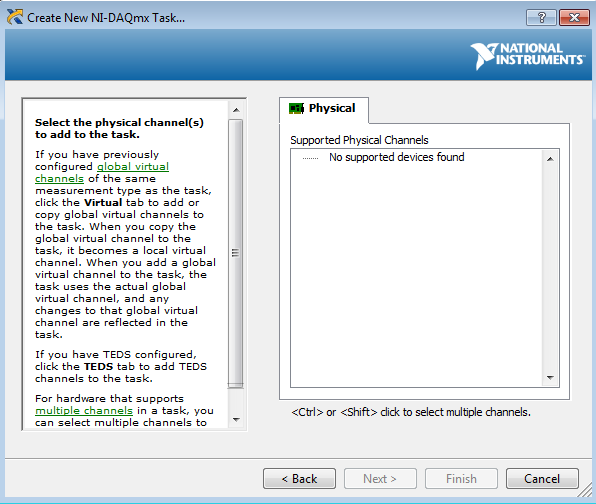
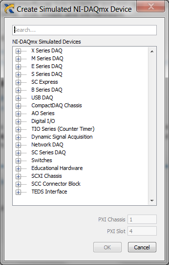
I just installed Labview 2015 and DAQmx 15.1.1. I am unable to find digital 6552 or 4130 4110 power supply cards or an i/o card in the list of simulated devices.
This screenshot shows the entire list that I can see. No power option.
Do I need additional drivers until I see these devices?
None of those are DAQ devices so expect them to be missing. Download the correct drivers (DC-Power, HSDIO) and go from there. I'm not sure of the digital camera, but I think you can use others with IVI and capacity of simulation.
-
Complete equipment of simulation using LabView, Multisim, and MAX (easy answer accepted!)
Hello, all!
Sorry, I'm new, but I checked around for a definitive answer on this, but I'm not 100% sure. I learn LabView for a physics of upper-division course. We use hardware (DAQ - MX) and a mixture of laboratory equipment - mainly stuff such as voltmeters, oscilloscopes and test setup with simple components. I also work with NIM instrumentation, but that's secondary to my needs here. So, when I'm away from the school, is it possible to make a complete simulation of my classroom work using LabView, Multisim (for my model) and the measurement and Automation Explorer (for the acquisition of data-MX)? I know I can create a circuit and drop it in Labview, but I'm not sure on the acquisition of data. I hope for what is a "seamless" reconstruction of what I do in class. I can't take a simple 'yes' or ""; as long as I know it's possible, I can find the solution.
Thanks for the help!
I wrote 'sim' screws in many situations where I need to work away from the hardware store. I think that MAX has a few features, but you may be limited in the types of signals, you can simulate.
For my sim screw, I make a copy of the original VI with ".sim" added file name. I also change the icon in a characteristic way to identify the version of the sim card on the BD. In this way the two VI have the same connector pane and are interchangeable on the BD structure. disable the diagram can be your friend here. Inside of the VI of sim, I generate the signal in any form I want. You can also add additional if necessary controls.
Lynn
-
Can't find USB-6009 simulated in list
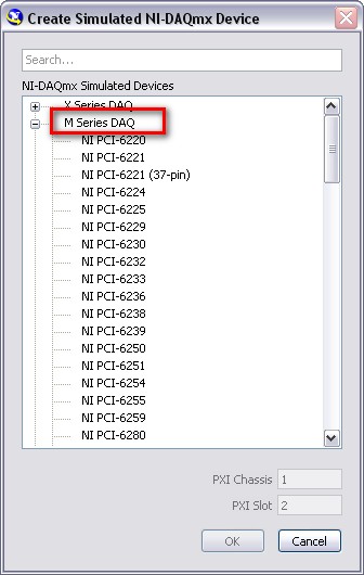
In automation solutions Explorer, when I try to create a new OR-DAQmx simulated device, I can't find the USB-6009 case. Looks like it would be under the heading USB - DAQ, but all that's there is the 9000 series devices. The 6000 series are not available as devices of simulations?
Tim
Hi Jordan,.
Box USB-6211 is actually a M Series family. Expand the M series: DAQ when creating your device simulated, then scroll down to the list of USB devices. Hope this helps!
-
without using DAQ how a PID controller for temperature control
Mr President.
IAM trying to make a PID controller for temperature control in labview. But I have no devices data acquisition. Then without using DAQ how a PID controller.please suggest some useful block diagram.plz give me an answer. I tried one, but not working.below attached is my work.
as a learning exercise, some devices can be simulated in the Explorer to measure (performance measure explore, right click on devices, select Create new.) Select simulated device and choose your device, you can search by product code for example 4070 for a dmm)
I hope this helps you begin to learn labview, depending on how advanced you can I strongly suggest looking in training of core 2 and core 1 but also by looking at the examples that come with labview
-
Control and simulation and data acquisition
Hello
I am applying to motor control in Labview. I'm sampling speed from DC engine in real time through an acquisition of data. (my sampling time is 1000 samples per second)
Then wrap speed as input to a Simulation (simulation and design of the order) and inside the loop simulation, I have a PID controller. The PID has the actual speed of the engine for the acquisition of data and the engine reference speed as input.
Reference engine speed comes from the generator of signals (control design and simulation-Simulation) and is a waveform.
My step in the engine size is 1000.
I am running this application real-time and drawing the reference signal and the motor real signals. I run into several problems with regard to the calendar.
1. when I change the size of the step of the simulation loop, the frequency of squares of reference also seems to change. For example. What step size = 1000, duration of pulse = 1 s. What step size = 100, pulse width = 0.1. (My pulse frequency is 1 Hz, Simulation clock - 10 kHz). How step size can affect the pulse width.
2. can you explain the relationship between the DAQ, the Simulation step size loop sampling time, Loop Simulation period.
3. If I want to collect different sets of data using sampling different hours, it's OK to change the sampling DAQ time without changing the size of the step of the simulation.
Would also like to emphasize that the DAQmx calendar under sample clock mode is placed in front of the simulation loop and the output is connected to the loop simulation.
Appreciate any help.
Hello
Maybe some screenshots of your code would help. Furthermore, what you have read your samples together with your DAQ screws?
(1) If you have a waveform, the output is specified as:
For example, if you change the size of the step of the simulation loop, you change the simulation time which are introduced into the signal generator and affecting the waveform that you see if you do not have a size quite small step to characterize the waveform that you generate.
(2) sampling DAQ rate is the speed at which samples are taken on the acquisition of card data itself. The size of the simulation step, help. "Specifies the interval between the time when the ODE Solver evaluates the model and updates the results of the model, in a few seconds." Simulation loop, still using, "Indicates the amount of time that elapses between two subsequent iterations of the loop of control & Simulation.". " "Step size determine the value of t that is introduced to the functions you use in the loop simulation while the loop simulation period controls simply to how fast you change the following t value. The sampling rate of DAQ hardware is a clock of completely separate hardware controlling the analogue-digital on the DAQ card converter so that you can get a deterministic dt between the samples being acquired.
(3) you can change the schedule for the acquisition of data, but you will need to restart each time the changes take effect. If you change the calendar of data acquisition and want your values to correlate with your simulation, you will need to change your size of step as well.
-Zach
-Zach
-
I am a new user and am confused by the signal provided by devices simulated in MAX and can't find an answer anywhere. I'm using Labview 8.2, MAX 4.2, DAQmx 8.5, cDAQ-9172 and the DAQ Assistant, simulating a 9215 card. I understand that the simulation is a noisy sinusoid, but what is the frequency of this wave? It seems that you can change with sync settings in the Configuration Wizard panel.
It seems to me that sync settings would deal with the samples the 9215 incoming signal, right? On the contrary, it seems that these timing parameters change the frequency of the signal itself. For example, in the DAQ assistant, if I run a test field absorbing N samples and read samples of 1000 to 1 k Hz, I see a cycle of a noisy sinusoid which takes 1 sec. If I read 100 samples at 1 k Hz, I see a noisy a sine wave cycle (with less resolution) which takes 100 ms. This does not mean that my frequency signal has multiplied by 10? I expected to see only a part of a sine wave had the original frequency remained the same.
Also, when I run using acquisition mode continuous sample it seems that the time required to go from Ridge to Ridge is different once again. Here, he does not appear to make a difference in what is the sample size, but rather what is the sampling frequency. 1 k Hz, it takes about 10 seconds and 2 k Hz, it takes about 5 seconds.
Please be aware that as a newbie, I'm not far enough along to fully dissect the DAQ assistant VI to see what is happening, but who will be the next. So, I would appreciate any simple explanations as to why I see what I am.
Hi pfrank.
It is not documented, but the simulated sine wave (measured in samples) period appears to equal the size of memory enter task buffer, at least for the tasks of buffering. The size of the input buffer is based on various factors (finished/continuous samples, by channel, sampling frequency). These are explained in the NOR-DAQmx help file that is installed in the Start Menu under National's Instruments\NI-DAQ. Search for "How is the buffer size determined? (without the question mark)
The selection of N samples leads to the DAQ Assistant set the mode of the sample to over, so the size of the buffer is exactly equal to the samples per channel. If you select continuous samples instead, the size of the buffer will have the value 10 kS because the sampling frequency is between 100 s/s and 10 kech. / s and period of the sine wave will be 10000 samples. If this doesn't make sense, look at '' How is determined to buffer size? '' in the NOR-DAQmx help.
DAQmx does not support the provision of your own simulated devices simulated data. If you want to control the simulated signals, you need to add code to your application that replaces the data returned by DAQmx.
Brad
-
CQI RTD sample.vi with simulation device
Hi all
I am student on samples DAQ in labview 2009, I have no DAQ hardware, but I faked 9188 NI and NI 9214 (thermocouple). I want to run 'acq RDT sample.vi' devices with these simulated, but when I run the program it displays error "possible reasons: device to which is attached the sensor doesn't have a source of available internal excitement." Select another device with a source of available internal excitation or provide external excitement. ». However, in the web, it is said that NEITHER 9188 and NI 9214 are available for real-time measurements. What is the problem with that?
What Jacob said, is that the 9214 is not designed to work with the RTD sensors. An RTD is a resistance that changes the value with temperature. A thermocouple produces a voltage proportional to the difference in temperature between the junctions. A measurement system for thermocouples need measure the voltage and often compensates for cold junction temperature. A measurement system for RTD must measure the resistance which is generally to provide a current, and then measure the voltage drop. The 9214 is not a supply for RTD current circuit.
The specificatioons for the 9214, it seems that it will work with the real time operating system.
Lynn

Maybe you are looking for
-
I'm trying to airtime of various Apple devices to my AppleTV. When you try to do, I'm getting audio but not vision. When return to Apple devices, everything works normally again. I guess there is a problem with my AppleTV. It doesn't seem to matter w
-
Hello. So I have a question. Is the latest version of the BIOS for a Dell XPS 730 x 1.0.5 or can the 1.0.6 version be put on? I can't find a boot option in the BIOS from a USB flash drive 1.0.6. Current operating system is windows 7 ultimate.
-
image size shortcut stopped working...
Even if my keyboard works fine, the shortcut for the size of the image produced nothing. I have too many images to work to go to the drop down list every time. Nothing happened to the computer or the keyboard. It has just stopped working.I'm a long t
-
Hello! My name is Deborah and I have to just use CC. The issue is that I am the Spain and Ps its been installed in Spanish, but I want it in English! How can I change?Thank you!!
-
Difficulty to remove the power to Optiplex GX 280 SFF
I'm coming out of the SFF power supply. I press the round green paw and try to slide the device forward but don't can't make it move. Tips on how to free up?