[SOLVED] - counting Webcenter
Anyone know tell me if have a tool that could be used to work with skinnings in archives CSS?Published by: Thiago V Palmeir 15/09/2012 18:48
Hello.
I've got next recommendation on WebCenter counting.
Application of Portal:
-Copy & paste skeleton portal - skin.css provided with the default application. It provides main components skin selectors common webcenter as showDetailFrames of components etc...
-Use ADF Skin Editor (IDE) as a useful tool to view and change items ADF selectors.
Application of space:
-Download DesignWebCenterSpaces and see the base sample Skin.css
-For components of the ADF use ADF Skin Editor too.
Tips:
-Use the skins of hierearchical if you want to create the same skin CSS base for other skins.
-Always use selectors skin ADF instead of the HTML generated code in your CSS. For example: td + td... is not good practice
-Build your page layouts. Here you have a very good guide to page layouts with tips for spaces and applications Portal: http://www.oracle.com/technetwork/middleware/webcenter/portal/learnmore/pagetemplates-1438595.pdf
I hope this help you
Tags: Fusion Middleware
Similar Questions
-
Unprintable area on the Photosmart Premium
Where can I find a specification of the unprintable area of the paper for C - 309 has? Single and double print side?
How can I set the location of the header and footer when printing in Firefox (both on Windows 7 and Ubuntu 12.04)?
I guess my problem is solved, count below, but my initial question about the unprintable area on the short sides of a sheet by using the duplex (two sided) on Photosmart Premium module remains unanswered.
Windows 7
Devices and printers - Preferences - Advanced done printing not have to option borderless printing, but minimize margins. The features tab has the choice without border. With selected borderless or double-sided, or multiple pages per sheet printing can be selected.
I did some tests and got the following results:
I can't reproduce cropping of the left on the left page margin when printing two pages on a single sheet. But what print two pages on a sheet using print duplex printing is distorted. The print is compressed along the long side of the sheet, thus giving more wide margins on the two short sides of the sheet. The print was made from MS Publisher 2003.
Ubuntu 12.04
Selecting A4 borderless och A4 paper of small margins results in failure to print.
Printing from cultures of high LibreOffice, first print 15 mm from the edge, with simple print face and two back on odd pages. Two sided using the text on pages is lower so the top is printed OK. Instead, the background text is cropped, last photograph 16 (15?) mm from the edge.
Export to PDF format with later printing prints OK but the scale is the text so that the text begins at 17 mm high and ends at 20 mm from the bottom.
-
Count only the iterations of duplicates? [SOLVED]
Using Oracle 9i 9.2.0.6.0.
This could be something simple that I am on, there are plenty of ways to find and count duplicates but I'm looking for a way to count only the number of iterations of a duplicate, it is and then group them if possible.
For example, suppose that you have
So I don't want to go back to the following:store customer product date 1 John A 2008/05/01 1 John A 2008/05/01 1 John B 2008/05/01 2 Bob C 2008/05/01 2 Bob C 2008/05/01 3 Mary D 2008/05/01 3 Mary D 2008/05/01 3 Mary D 2008/05/01 3 Joe F 2008/05/01
I want to only count how many duplicates beyond the first row for each store, where a duplicate has the same store, the customer and the product. ThenStore Duplicates 1 1 2 1 3 2
1 John A 2 Bob C, had one double, and Mary has 2.
I've tried so far to use analytical functions to subtract the first value of each partition before doing a count or make a number from each partition but niether seems to work by a group of store.
Published by: a little rabbit on September 18, 2008 13:03You can find the number for each group and subtract one, as follows.
SQL> create table t ( store int, customer varchar2(10), product varchar2(1), d_ate date );

Table created.

SQL>
SQL> insert all
  2     into t values ( 1, 'John', 'A', date '2008-05-01' )
  3     into t values ( 1, 'John', 'A', date '2008-05-01' )
  4     into t values ( 1, 'John', 'B', date '2008-05-01' )
  5     into t values ( 2, 'Bob',  'C', date '2008-05-01' )
  6     into t values ( 2, 'Bob',  'C', date '2008-05-01' )
  7     into t values ( 3, 'Mary', 'D', date '2008-05-01' )
  8     into t values ( 3, 'Mary', 'D', date '2008-05-01' )
  9     into t values ( 3, 'Mary', 'D', date '2008-05-01' )
 10     into t values ( 3, 'Joe',  'F', date '2008-05-01' )
 11  select null
 12  from   dual;

9 rows created.

SQL>
SQL> select distinct
  2         store
  3  ,      cnt - 1 as duplicates
  4  from  (
  5         select store
  6         ,      customer
  7         ,      product
  8         ,      d_ate
  9         ,      count(*) over (partition by store, customer, product) as cnt
 10         from   t
 11        )
 12  where  cnt - 1 > 0;

     STORE DUPLICATES
---------- ----------
         2          1
         1          1
         3          2
Concerning
-
[Solved] Clicking on a tab on the bar tab selects the wrong tab.
Firefox 34.0.5 running
Sometimes, but not always, by clicking on the tab bar opens the wrong tab.
Rather than open the tab is selected, it will open a tab completely to the left, in the corresponding position, rather than the tab I have click on.For example, this image shows the tab I click on.
http://PUU.sh/eAfsP/7ddac08d41.PNGAnd this picture shows the tab firefox passes instead.
http://PUU.sh/eAg4Z/2b4f441564.PNGNote that it has instead moved to the left end of the tab list.
It may be interesting to note that my firefox is running with about 300 individual pills, of which about 30 are loaded at any point and time. However, please do not attribute the problem to the count tab without reason, because this question has ever taken place in all previous versions of Firefox.
[Solved] There was a conflict with an extension that appears to have been resolved.
Thanks for your help the-edmeister, I found the cause of the problem, it turns out to be an extension of the buggy, called Classic theme restaurateur 1.2.8.2.
It has been used to go back to an older version of the firefox theme, and unfortunately, it seems that bugs have been introduced as it became obsolete after several versions of Firefox.
-
Count multiple responses in a single cell
I have a spreadsheet with data in an investigation. Some questions have more than one valid answer. In these cases the data were entered in the same cell. So, I have a column that looks like this:
Green, blue, Red
Blue, Orange
Yellow, green, blue
Black, green, red, Orange
And so on...
I can't understand how to count the number of 'Green' for example.
In excel I use this formula:
= SUMPRODUCT (-IsNumber (Search (text_to_find, within_text)))
I try to convert it to changing number ISNUMBER (for NOT (ISERROR (but does not work.))
What I am doing wrong?
I would solve you the problem like this:

Make sure that the table has two header lines by selecting the table, then using Table formatter:

Now add the colors all row 2 of the table, as shown.
B3 = if (a3≠"", Len ($a3) ≠Len (Substitute($a3,B$2,) "", namely "))," ")
It's shorthand dethrone select cell B3, and then type (or copy and paste it here) the formula
(= IF (A3≠"", LEN ($A3) ≠LEN (SUBSTITUTE($A3,B$2,) "", namely "))," ")
Select cell B3, copy
Select cells B3 at the end of the G column, paste
now to count the occurrences of each color:
B1 = COUNTIF (B, TRUE)
Select cell B1, copy
Select cells B1 to G1, dough
-
Photon counting using Photon unique cash Module and PCI-6602
Hi all
I am currently working on program couting of photons using a single (Excelitas) and PCI-6602 photon counting module connected to the BNC-2121.
I took a glance at other positions, but I still couldn't solve my problem (or, again, I'm not sure if yes or no, the problem is the specification of the material).
In the program, I'm generates a trigger to 1 MHz pulse using a trigger in a separate loop.
Other than that, I have loops of the producer-consumer model to get data and do a simple subtraction to calculate the number of photons in 1 microsecond.
According to the values connected to 'Input.BufSize' of buffer DAQmx and "Samples per channel" DAQmx calendar, I could change the loop number that the program has done its job correctly.
With the values, the program acquires photon 1 MHz with signls for 139 times.
After that, the program stops and the loopback number increases very quickly.
When I forcifully took stop the program, while the loop number increases very quickly, the program appears "error-200141".»
The error that says "data has been replaced before it can be read by the system." Mechanism of data transfer is interrupted, try to use DMA or USB in bulk. Otherwise, divide the input signal before taking the action. "even if the meter explicitly works in DMA mode by using the sample clock.
I wonder there is nothing that can solve my problem or even the only solution will buy a better Board of counters/timers.
Thank you all for reading this.
I will be very happy with any index

Kind regards
Myeongsu
Yes, the same thing happens on my system.
It does not happen with PCIe-6612.
I found more strange things:
When I start to reduce the frequency at a time given (800kHz) can fill the buffer, it will not start since the beginning of the buffer. He can go to the beginning of the buffer only at 100 kHz for my PC.
Options to fix:
(1) PCIe-6612. Seems to work. I tried streaming at 10 MHz, 5 min - fine.
(2) reduce the frequency of the pulse. If your laser supports 100 kHz, you're fine.
(3) put in place additional synchronous counter at 100 kHz. Basically, it's material average number of photons by 10 pulses.
(4) read 2 adjacent pulses each 1/50 kHz - then your data transfer will be 100 kHz and you will get the number of photons of this impulse of the 20 - th.
Programming issues:
(1) remove the display of the received picture, make only the processing of data and show results if you really need it.
(2) clock.vi sample sets the buffer size, if you specify the size of the buffer, do this after this vi.
(3) I deleted unnecessary "loop generation." He is running on the hardware and stops when you stop it - after reading the loop ends.
-
Problem with signals TTL metering: confused with counting
Hello
I use a TTL of 0.2 Hz signal to synchronize two devices. I use a Usb-6210 card to count the pulses TTL. The meter goes off when it detects the edges increase. In my case, the meter was sometimes triggered at low altitude, which causes wrong results (see attached pictures, the TTL signal is sampled at 20 Hz and the dots represent an increment of the counter). How can I solve this problem?
In addition, the cable that connects the TTL output was welded by myself, would that be a problem of bad contact?
Thank you very much
K-X
What is the nature of the device producing the TTL trigger signal? Is it possible, for example, that it could produce a 1 microsecond pulse (which might not be visible on your signal ground) that would trigger the meter? You really produce a digital pulse (i.e. your something circuit which is 'on' or 'off' as opposed to 'product analog voltage in the range of 0 to 5 volts')? Are there any other devices around that could produce the impulses that are "picked up" by your meter? The cable connecting the TTL is armored pulse for the meter? The shield is based at one end?
These questions (and the previous) suggest that the problem may be 'electronic' rather than 'LabVIEW '...
-
Hello
I have a power meter which provide the USB driver and a Labview program to get the data and NI USB-6221. The project I am currently working on the needs of:
1 acquire two signals (inputs of simple tension), pressure frequency KHz
2. acquire a flow signal, the output signal is 0 to 5V pulse, each pulse means 0.4 ml volume. So I use a voltage inflows to count impulses in certain period of time (in this case, 1 S) for water flow. ; KHz sampling frequency and the 1 Hz update rate
3. acquire a signal of engine speed. The output signal is pulse square wave whose frequency is related to the speed. I use a REIT port to measure the frequency. Sampling rate: Auto
4 give output voltage sine or square wave, I use AO do that.output rate: Auto
5 acquiring by VISA electricity meter data. Data update rate: every 50ms
Currently, all the 5 tasks work well separately. But when I put them together, some signals are beginning to hang, for example, pressure signals sometimes give nothing.
Another problem is the data record. I programmed the VI in such a way that whenever I press the button 'save start', he begins to record data and save them in a .cvs file. For some reason, I always get only the data in the first table. Coult someone help me? I download my code as follows
Hello
What I meant by open, write, close. For any type of file you are using.
Open the file, which produces a reference, then put the mention in a registry to offset.
Write data, using the function write (for this type of file) and the reference.
When you are finished, close the file reference.
Writing in the spreadsheet opens, written, close all at once. It is very good for this type of application.
***
The issue of the loop is more general. I would like to say first of all, I want to say that since each loop works on its own, it is own VI, and that this program has put all this into a single VI, which has a method to solve the problem is to disable all the loops and allow them one at a time to see if there is a culprit responsible for.
Using multiple loops executes the code at the same time, and some loops would be cycle faster than others, especially if some of them are loops just as they are.
Communication between the loops is a test to the address if necessary.
Running all these signals through different loops DAQ must also be examined. Don't know what questions are for read and write somewhat randomly in the channels.
-
Deadline for redeclenchables counter finished
Hello I am new to labview and using a pcie-6323 and had some problems clock. What I'm trying to do is a counter to generate a clock (picture in the figure) and based on it to trigger and generate a different "trigger camera clock' to trigger a camera. Trigger camera clock is a desk finished, redeclenchables. It is a code writtern by former laboratory. Previously it worked very well.
Recently, I would like to add a constant delay for all trigger camera clock pulses, not just the initial one. When I saw this example, https://decibel.ni.com/content/docs/DOC-10685, I tried to add the start.delay to my code, as in the following figure. But once I run the program, I got a 200452 error code and the program must be closed.
I saw this link mentioned to use activate Initial on Retrigger. delay, http://digital.ni.com/public.nsf/allkb/204538A044431C9B86257377004EB952 . But I tried to put it in several different positions, for example after the Creat channel vi, after the moment where vi, after the left trigger vi and the node property trigger, I have always the same error problem.
I think that the pcie-6323 should be with the STC3 timing engine, http://www.ni.com/pdf/manuals/370784g.pdf , so I don't know why I got the 200452 error. I wonder if there is a simple way to solve this problem and reach my goal. I have seen a few examples used two counters to this late, but I think that there should be an easier way? If anyone can show me a figure or taste vi, it would be very useful. I really appreciate it!
Thank you very much!
Startup time is bad, use Initial delay (entrance in create virtual channel - original 0.0008 trigger closed task of the clock). Delay enable initial on retrigger applies to it.
Another way is to use frame duration clock pulse (duty cycle) as control to delay - start a task on the forehead and the other - on falling edge.
-
count the pulses ttl only on 2 V
Hi I have a problem while I was trying to count a pulse ttl using the DAQ Assistant. The problem can be simple, but I just can't solve that since I'm new to LabView.
There is a TTL pulse produced of our ODA that is about 30 ns width, 5V. I want to use LabView to perform the count of photons. But because of the noise, I want to put a number limit of 2V, so the software one count higher than 2V TTL pulse. But I can't do that. There is no option to set the limit.
And our material is BNC-2110 and PCIe-6323.
Can someone help me with this? Thank you.
For a counter entry, the minimum voltage for logic there is 2.2 volts - a ttl level. And no, you can not adjust higher.
-
No count output / pulse pulse does in a meter of pcie-6320
Hi all
IM using pcie-6320 in my application to generate impulses using the counter i/o.Even when I try to generate/counting pulses using MAX, I coundnt find no exit, im watching the e/s using a CRO. My camera works very well and tested hardware DAQ Diagnostic Utility tool in this tool also spent the meter test. IM completely stuck here, if anyone has come across such a problem please help me.
Hello.. I solved the problem. In fact, it was found that the cable between junction box and data acquisition is not properly inserted. In any case thanks for your contributions
-
Read the counter timeout in synchronized to count-analog input
Ciao, Giovanni.
The two tasks are run in parallel so there is no guarantee which task starts first. I suspect that when you are away from the counter samples, it is because the task of analog input before starting the task of counter. In this case, the task of counter would be ready to accept examples of clock and may be missing some edges of the clock at the time wherever he is started.
One way to solve the problem would be to use the wires of the error in order to ensure the time started the task of counter in front of the task of analog input. You can also use a sequence structure to do that.
The counter is sampled on each edge of the sample clock HAVE no matter what you set the 'rate' of entry to the. When you use an "external" clock (external to the task that is), the driver uses just the entry rate to set some default parameters (size of buffer for example).
If you have any questions, feel free to ask!
Best regards
-
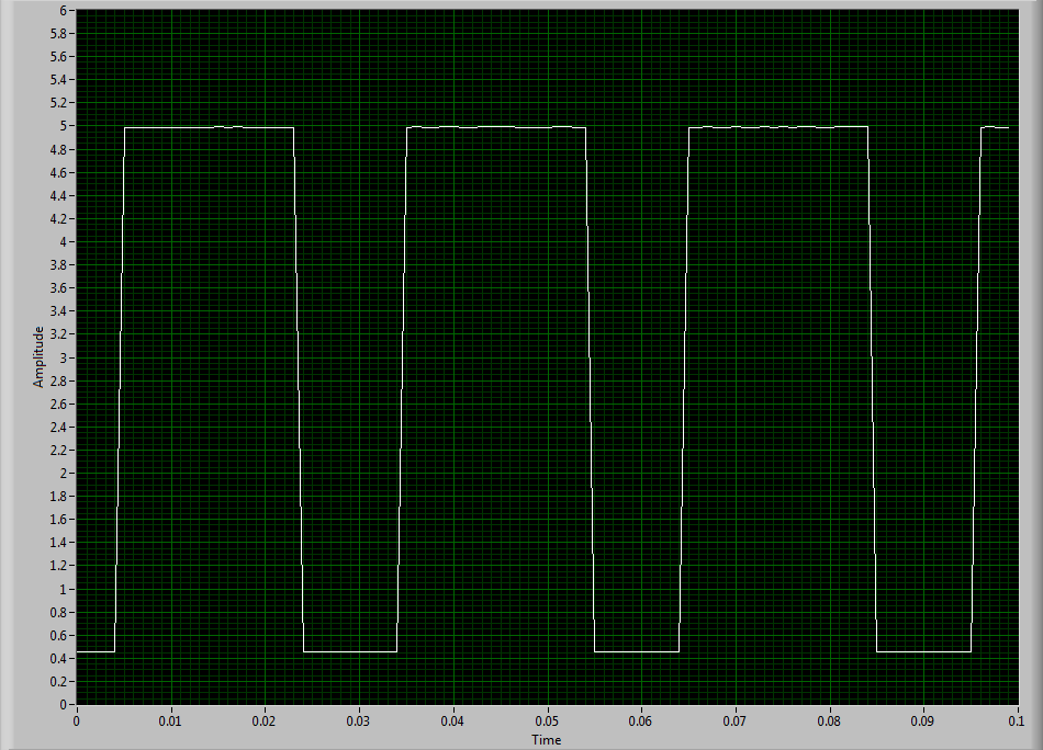
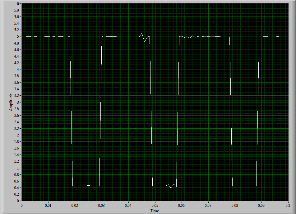
NEITHER USB-6343: erratic low frequency 1 counter measures
Dear members,
I'm looking for help with a measure of low frequency counter. I tried to make it work for a week or two, but I keep getting erratic measures. It will read the rpm properly for a second or two and then it will give a ridiculous value on the order of 10,000 times the correct value. I can not get a constant value.
I use a DAQ series X NI USB-6343 multifunction with Geartooth Honeywell GTN1A111 sensor. I enclose a sketch of the wiring configuration. I think that it is correct. Sensor output to the door of the meter.
To try to solve this problem, I hooked the sensor to an analog input channel to make sure that I was getting a TTL signal by sensor. I noticed every once in a while I'd see a glitch of little noise in the signal and I guess that's what is causing my problem with the meter. I inserted two waveforms of the sensor signal (one with the clean signal) and the other with the glitch of noise. My understanding of a TTL signal meter channel will examine LO voltage when it is below 0.8V and HI when it is larger than 3.8V. So I really do not understand why these little glitches could be the cause of the problem because they are well below and above 0.8V and 3.8V, respectively. I think that the noise comes from a frequency converter used to drive the engine. I tried the system as much as possible of the Earth.
I guess I'm looking for another approach. I could potentially use a digital filter to help with noise? The glitch is in fact the problem or I forgot something. The VI in question is attached.
Thanks in advance,
Mike
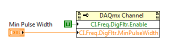
Have you tried to set up a digital filter yet? Obviously the seeds are collected as an additional transition (the method of low frequency counter 1 measure the period and then reverse, so a short glitch would record as a very high frequency).
You can enable the digital filter with the following property node:
Min pulse width is guaranteed pulse past the filter, so it should be low enough for the real signal is guaranteed to pass through (but high enough so that the glitch is always rejected).
Best regards
-
Erratic counting quadrature encoder
Hello
I try to use LabVIEW 9.0 and an acquisition of data USB-6212 for measuring angular displacement of rotating quadrature encoder (digital model we E2) attached to a linear actuator based on the stepper motors.
With the help of the VI linked to below and the default PFI pin on the acquisition of data, I can get the Angle of the VI to change, but with two issues indicator.
http://forums.NI.com/attachments/NI/170/144774/1/QuadratureEncoderM-series.VI
1. the only way I can assure you that the Angle indicator remains at a constant value with the VI running and the stepper motor moves do not is to turn off the power to the encoder. In other words, when the 5V power is provided to the encoder, the Angle indicator sometimes remains constant at a certain value and sometimes increases, even if the motor step does not move. I added a waveform table that displays the Angle to see more easy output.
2. with the engine not to not pass any if she moves hourly or counterclockwise, the angle indicator only increases (counting). Changing the direction of engine displacement does not decrease the angle.
I checked the DAQ pins I use: PFI 3, Z = A = B = 11 PFI with ctr and PFI 4 1. I tried both ctr0 and ctr1 with the same results. I used a multimeter to check the outputs a, B and Z on the encoder to output with the motor step-by-step to displacements of various populations, and I'm getting ~ + 5V sometimes and ~ 0V sometimes telling me that the encoder, which is new, seems to move from high to low.
This sounds like the kind of behavior that may be caused by noise in signals? If so, who should not have something to do with the Angle only, correct? To get the Angle to reduce, should I change something in VI?
I thank you very much for any assistance, you can give.
Hi Mike,.
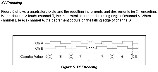
From what you describe, I feel the symptom of the meter backwards never is a side effect of the issue where the meter continuously counts up while in not moving. This really looks like a noise problem, and there are a few small but noticeable spikes in your graphics HAVE you provided. Basically, as long the (Source) Signal led B Signal (to THE), then the meter progressive count. This is for X 1 coding, which I assume that you are using. Look here Figure 5, in virtue of the X 1 section for how this encoding reads your signals of encoding:
Your connections you describe are correct, so it'll be a matter of getting rid of the problem where the meter is incremented on its own which I believe will solve your other problems. Take a look at these links to see if adding filters on the internal counter inputs to the card allows the measurement: Activate the digital M series filtering allowing digital filters for TIO Debounce NOR-DAQmx devices
-
Point by point count in a window
I am a user of labview 8.5 working in the field of aerodynamics - namely laminar boundary layer turbulent transition.
I want to take a signal high-pass filtered, rectify, and then place a window around the remaining signal (equivalent to 10% of the average of the signal not filtered) and count the number of points both inside and outside the window. I can use a histogram for this as in the attached vi, but I need to do an analysis point by point, because the things that pass through the window faster than a length of residence requirement should be considered as turbulent instead of laminar.
To say more explicitly the points above the average of 10% get digitally assigned 1, anything less than 0, but say that part of the signal less than 10 consecutive zero points are sandwiched between two 1 then they need to be addressed as 1 also. Where 10 points in a row to my frequency equals my critical residence time.
I hope I have given you an adequate description of what I'm trying to achieve, could someone direct me to achieve this please? I am not too concerned about the filters, frequency etc. are used at the present time.
Thank you.
Solved. YeeHa!
I want to thank my family, friends (if I have) and sponsors...


Maybe you are looking for
-
Is it possible to have the reading Payne placed to the right?
I wish I had reading Payne on the right as in outlook.
-
Support for Windows 10 in Qosmio X 70 - has
Hello I have a X 70-a, and according to the plan of Toshiba support, full support for Windows 10 only will be available January 31, 2016 ('coz that's what you get when you pay 1500-2000 euros for a cell phone, right?) Any who tried to win 10 on a sim
-
My A30 won't let me use the softmodem AMR. I get error 000005aa, the port is used by another device. There is no error in the Device Manager, it indicates that the modem is enabled and Ok no conflicts, but when the modem is queried using the diagnost
-
Satellite L500-13W: how to enable the Wlan with Win 7 - shortcut keys do not work
Hello I recently acquired this laptop and I installed win7 64-bit teacher. The first problem was that the wireless card has not been installed, but I go to the Toshiba website and download the new one, next to this i can not activate the map with the
-
lines on the screen of the computer
horizontal lines through my moiniter