Acquisition of 5732 NOR
Hi all
I have a 5732 NOR associate NI SMU 7962R, and they are integrated in a NI-SMU-1073 chassis. I wanted to test the data acquisition, so I plugged in a function to the AI0 generator. However, something strange happened. The acquired data seemed to be the derivative of the signal transmitted from the function generator: sine was still sinusoidal, but the square wave became pulse and square wave has become ramp! Has anyone seen what happens before? Thank you!
Best,
Tong
What was the frequency of the signals that you generated, and what are the options you have selected for the filtering and coupling AC/DC? If you have set for AC coupled entry or one of the active filters that resembles the behavior expected if the signal of interest is located in the strip of mitigation.
Tags: NI Hardware
Similar Questions
-
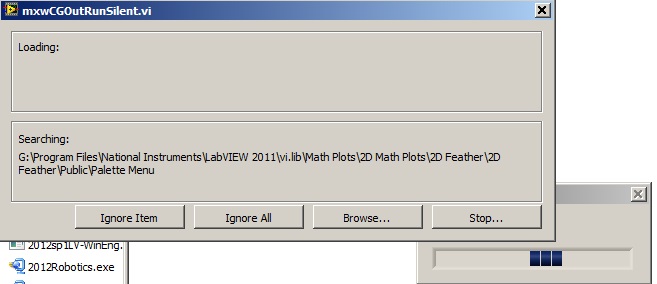
Acquisition of data NOR usb 6008: a strange problem: mxwcgoutrunsilent.VI is not respected
Expensive OR
Today, I bought an acquisition of data NOR usb 6008
and I'm using labview in 2011
the problem is appear when after I end the process of configuration of the i/o data acquisition Wizardthe following image shows the mxwcgoutrunsilent.VI is ignored and an error has occurred
someone can help provide this VI for me
What is the complete labview modules can also so I could do a real time data acquisition
Best regards
mangood,
You received an error code? If so, what is it? What version of NOR-DAQmx driver you have installed? It seems your driver potentially incorrectly installed, and you may need to reinstall the driver.
Here is the link to the latest version of the NOR-DAQmx driver: http://www.ni.com/download/ni-daqmx-9.8/4297/en/
-
Question about the Acquisition continues through NOR-DAQmx
I'm a bit new to NIDAQmx methodology and I was wondering if someone could could give me some advice on accelerating certain measures of tension that I do with a case of DAQ NI USB-6363.
I have a python script that controls and takes measurements with a few pieces of equipment of laboratory by GPIB and also takes measurements in the area of DAQ OR DAQmx via (I use a library wrapper called pylibdaqmx that interfaces with the libraries C native). As I do with the data acquisition unit is 32 k samples at 2 MHz with a differential pair to AI0. An example of code that performs this operation is:
from nidaqmx import AnalogInputTask

# set up task & input channeltask = AnalogInputTask()
task.create_voltage_channel(phys_channel='Dev1/ai0', terminal='diff',       min_val=0., max_val=5.)
task.configure_timing_sample_clock(rate=2e6, sample_mode='finite',
      samples_per_channel=32000)

for i in range(number_of_loops):  < ... set up/adjust instruments ... >  task.start()  # returns an array of 32k float64 samples  # (same as DAQmxReadAnalogF64 in the C API)  data = task.read(32000)  task.stop()  < ... process data ... >

# clear task, release resourcestask.clear()del task< ... etc ... >
The code works fine and I can all the 32 k spot samples, but if I want to repeat this step several times in a loop, I start and stop the job every time, which takes some time and is really slow down my overall measure.
I thought that maybe there is a way to speed up by configuring the task for continuous sample mode and just read from the channel when I want the data, but when I configure the sample for the continuous mode clock and you issue the command of reading, NOR-DAQmx gives me an error saying that the samples are no longer available , and I need to slow the rate of acquisition or increase the size of the buffer. (I'm guessing the API wants to shoot the first 32 k samples in the buffer zone, but they have already been replaced at the time wherever I can playback control).
What I wonder is: How can I configure the task to make the box DAQ acquire samples continuously, but give me only the last 32 samples buffer on demand k? Looks like I'm missing something basic here, maybe some kind of trigger that I need to put in place before reading? It doesn't seem like it should be hard to do, but as I said, I'm kinda a newbie to this.
I understand the implementation of python that I use is not something that is supported by NEITHER, but if someone could give me some examples of how to perform a measure like this in LabView or C (or any other ideas you have to accelerate such action), I can test in these environments and to implement on my own with python.
Thanks in advance!
Toki
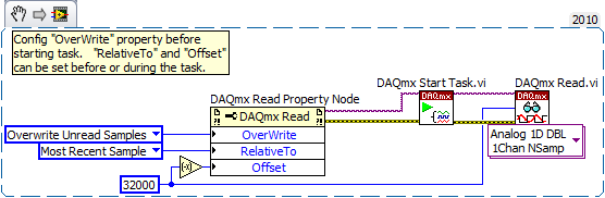
This is something I do a bit, but I can only describe how I would do it in LabVIEW - I'm no help on the details of the C function prototypes or the python wrapper.
In LabVIEW, there are accessed via the 'DAQmx Read property node' properties that help to implement. One is the Mode "crush" which I'm sure must be set before performing the operation. The other pair is known as "RelativeTo" and "Offset" and they allow you to specify what part of the CQI data buffer to read data from. If you the config to "RelativeTo" = 'most recent sample' and 'Offset' =-32000, then whenever you read 32000 samples, they are the very latest 32000 which are already available in the buffer of data acq. Between the readings, the task is free to overwrite the old data indefinitely.
Note that you will need to do this continuous sampling mode and that you can explicitly set a buffer size smaller than the default which will choose DAQmx based on your fast sampling rate.
An excerpt from LV 2010:
-Kevin P
-
Simultaneous to the AO and HAVE with the acquisition of data NOR USB 6001/MATLAB Toolbox
I am very new to data acquisition and bought a NI USB 6001 to start to learn. Because I can get free MATLAB through my University, I use Matlab data acquisition Toolkit as the data acquisition software.
My problem is that I get the following error message when I try to generate an AO (an LED voltage) signal and measure a signal I (voltage of a battery of 9V) simultaneously.
ATTENTION: This change is caused in the dump output data queue. Use queueOutputData for the queue data before the start of the object.
Hardware does not support the specified connection. Check the user manual of the device for the valid device routes and pinout.However to measure IA or by generating the AO each by themselves works perfectly well.
My Matlab script looks like this:
daq.getDevices;
s = DAQ.createSession ('or');
s.Rate = 1000;
s.DurationInSeconds = 10;
addAnalogInputChannel (s, 'Dev1', 'ai0', 'Voltage');
addAnalogOutputChannel (s, 'Dev1', 'ao0', 'Voltage');
aoVoltage = 1.8 + 0.1 * sin (linspace (0, 2 * pi, 10000))';
queueOutputData (s, aoVoltage);
s
startBackground (s);
Note that adding the channels HAVE and AO at the session also works, however I get the error mentioned at the start of the session. This is a limitation of my data acquisition hardware (I don't see something like that mentioned in the manual) or do I have to modify the script?
The pins connected for the LED are AO0 (+) and AO GND (-).
The pins connected to the battery are AI0 (+) and (-) AI4. (The problem is still there if I use the reference to the ground for AI)
6001 cannot make simultaneous tasks. Very standard limitation of the low-end hardware... just don't have on board computing resources to handle such things. Even the 621 x boards have only limited multitasking abilities.
Can intensify to a high range data acquisition ($$$) or buy a 2nd a low end and synchronize tasks in software (not as precise calendar). I've done two approaches, one is "best" really depends on demand... If low-cost or high-performance is a priority.
-
Acquisition continues using NOR-traditional DAQ
Hi all
For a new project, I have to use an old capture card, a PCI 4451 DSA. I LV 4.4.1 8.5 and MAX, so I had to install the 'Toolkit' for the traditional NI_DAQ.
Usually I use DAQmx screws, so I'm a bit lost with this screw...
What I want to do is continuous acquisition (see image).
Thank you for your help and I hope that we will find a solution. Thanks for sharing your experience with me.
Marc
Hello
check the attachment and try this...
-
ACQUISITION OF DATA NOR USB-6251
is it possible for the box USB-6251 to provide an output for a test set-up during playback of the inputs of the device even? for example: 10VAC Ridge to Ridge on the luminaire, mixed the sine and square wave signals of the luminaire to the data acquisition Toolbox.
Yes. The 6251 has two outputs analog and 16 analog inputs. Open finder example and looking for examples of both. Under input and output hardware > DAQmx > Syncronization > multifunctional, it is an example of analog inputs/outputs synched.
-
My acquisition of data NOR usb-6008, does not appear in labview after installing drivers
My DAQ does not appear in my labview program after installing the drivers. I can't add it to my program or anything like that. I installed 3 different drivers and updates, and it's still not appearing in labview. Is there something I'm missing or need to do yet?
Thank you
It seems that you have a damaged file somewhere in your installation. You will need to go into the control panel and select the option to repair the installation. You will need to run the repair twice due to a known problem. After that, you need to reinstall the NI_Daqmx 9.4.
Jacob K
-
Acquisition of data NOR-9205 Assistant set up range of input voltage
How to configure the module NI9205 to use the +/-200mV input range.
I use a custom scale, and it seems that I can not get an accurate reading. I use a shunt current of 100 Ma (max 10A). So I custom balance setting to have 100 x + b. The current flowing in the device is 2 amps and I get a reading of 12-13 amps after custom scale. Now I think the module is configured to sample for the entrance of 10V and I get an error of resolution.
Hi therbert
Since your custom scale is 100 x, to work on the beach of +/-200 mV to your NI 9205 module you must configure your input signal of maximum and minimum range for +/-20 respectively.
According to the equation: Range.max * scale.slope = 200mV * 100 = 20V
This will automatically configure to the scope of the module +/-200 mV to verify you can access the channel DAQmx property node and look for the analog input > General Properties > advanced > Range property, this will let you know in what range is the functioning of the device.
Concerning
-
Recommendation of USB data acquisition
Hello
I'm looking for a digital acquisition of data NOR-USB 12v e/s of at least 8 channels. He would be grateful if someone recommends me.
From what I can tell, the USB-6525 should work for you. It can accept a digital input of up to 60V (anything over 3, 2V is regarded as a MAXIMUM). And then there 8 SSRs to serve as exits Digital.
-
NOR-6008 selection file Matlab .m voltage range
Hi, I need to select a range of power such as - 1V to + 1V file .m in MATLAB to acquire data of acquisition of data NOR-6008.
I appreciate if someone can send me a code example.
The system works very well and I can control successfully the sampling frequency, but not the voltage range.
Concerning
Hello
The two alternatives are equivalent, option 2 is how to get to a channel if you had not registered to a variable when it is created.
When you say that it doesn't work, do you have an error message?
I just tried it on my machine with an NI USB-6008 with 4 channels and the range set to-1 [1] on one of these channels:
> s = daq.createSession('ni')
s =.
Session data using National Instruments hardware acquisition:
Will work for 1 second (1000 scans) to 1,000 scans/second.
Some channels have been added.> s.addAnalogInputChannel ('dev2', 0:3, "voltage")
years =
Session data using National Instruments hardware acquisition:
Will work for 1 second (1000 scans) to 1,000 scans/second.
Number of channels: 4
index of Type channel MeasurementType range nom_peripherique
----- ---- ------ ------- --------------- ---------------- ----
1 THE Dev2 ai0 (Diff) voltage-20 to + 20 v
2 THE Dev2 ai1 voltage (Diff)-20 to + 20 v
3 THE Dev2 ai2 voltage (Diff)-20 to + 20 v
4 THE Dev2 ai3 voltage (Diff)-20 to + 20 v> s.Channels (2). Range = [1-1]
s =.
Session data using National Instruments hardware acquisition:
Will work for 1 second (1000 scans) to 1,000 scans/second.
Number of channels: 4
index of Type channel MeasurementType range nom_peripherique
----- ---- ------ ------- --------------- ------------------ ----
1 THE Dev2 ai0 (Diff) voltage-20 to + 20 v
2 THE Dev2 ai1 voltage (Diff) - 1.0 to + 1.0 v
3 THE Dev2 ai2 voltage (Diff)-20 to + 20 v
4 THE Dev2 ai3 voltage (Diff)-20 to + 20 v
Properties, methods, events> s.inputSingleScan
years =
-0.0034 0.0008 0,0059 0.0012
Wael Bruno
The MathWorks
-
Here is my sensor
Pressure sensorHere's the DAQ data sheet:
Here are my issues:
First of all I don't know what is LO and HI exactly in the DAQ 9219 material.
Second, I don't know what pin code I should connect the DAQ sensor signal wire. PIN 4 or 5 pin? The sensor has three pins, and I guess I should connect the other two wires to the power supply.
Thirdly how to calibrate the sensor. In labview choose voltage in the wizard?I'm pretty new in this acquisition of data and I need your help.
Thank you
Hi SilasIII,
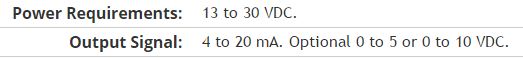
Hmm well 3 sons are probably on the ground, the power and the return signal. The datasheet for the sensor says:
First of all, you need to know which model you have (4-20mA, 0 - 5V or 0-10VDC). HI refers to the return signal, LO essentially means the land of the food that feeds the sensor. Then, you must get the 13-30 VDC supply. I don't think this should be too complicated and can be a simple wall DC power. You can learn how to create a custom in DAQmx scale. I hope that this is a starting point.
Kind regards
Eric
-
measurement of current with usb-6009
Hi, my name is hung and I am a student in electrical engineering... I'm doing a thesis that the project using Labview and acquisition of data NOR UBS-6009 to simulate the function generator, Oscilloscope, Digital Microsoft (DMM)... and now I'm simulating DMM. I managed to measure the voltage and resistance which i use voltage divider method, but I encountered a problem with the current measurement. The problem is the USB-6009 to measure use the current, it measures an incorrect value. I tried to use the current CQI 0-20mA Sample.vi example but it always measures an incorrect value. If NI USB-6009 supports for the measuring current? Is there a way to measure the currents using USB-6009? Please, help me. This thesis project is so important for me. Thank you.
Hung,
Since you are a student in electrical engineering, I'll show you how to know the answers to your questions.
1. review the specifications for the USB-6009 case. In particular look at the specifications of analog input.
2. How would you measure current if you had only a voltmeter? Use the same method with the USB-6009 case. (Tip: apply the Ohm's law).
General comment: when using any measuring instrument, always consider maximum permitted values at the entrances so that the instrument is not damaged
and the measure is accurate.
Let us know how you do.
Lynn
-
How to synchronize a DSA Board (4496) with several S-series (6143) tips for PXI?
I need to set up a data system that will require the measure to phase for accelerometers-locking and dynamic deformation signals. How to synchronize my PXI-4496 Council with my PXI - 6143 s?
I forgot that some DSA properties does not directly on the devices of the series S I have been able to find an article in the knowledge base that has addressed your specific issue.
Synchronization Dynamic Signal Acquisition (DSA) with NOR-DAQmx products, this includes an example program synchronization a DSA device and MIO device to sample at the same pace.
-
How to specify the sampling frequency? Must use "measurement & Automation Explorer '?
I use to measure the input current analog OR cDAQ-9171 (chassis only location USB) and NOR-9207. I have 2010 NOR-installed DAQmx and LabVIEW.
How can I specify the sampling frequency?
If I use M & A Explorer to create the task, I can specify the flow rate (Hz) on the Configuration tab-> sync settings.
For the acquisition of data NOR, it is mandatory to use M & A exploring?
If I don't want to use M & A Explorer, how can I specify the rate (Hz)?
Hello
You can specify the sampling frequency with "DAQmx Timing.vi" located in the function palette DAQmx (read context-sensitive help on how to use wisely).
You do not have to use M & A exploring (MAX) to create a task.
A simple and quick way is to use DAQ Assistant (same configuration as in MAX) to configure your measurement.
Another is to use blocks of DAQmx function to manually build your application code.
In my experience Assistant DAQ is ideal for simple tasks (one measure), with regard to the more complex measures (synchronized the analog and digital inputs).
I tend to use function blocks because they give you more freedom about code execution.
Note: You can also build DAQmx code from a wizard configured DAQ task.
Best regards
Matej
-
Hi all
I use an acquisition of data NOR-9205 Compact module to monitor several lines of pressure. I have the pressure transducers connected to DAQ module via more that 50' cable not shielded by line. There are a few noisy components in the test set-up, a bunch of heat automatic start/stop function and a spark igniter. These two elements to cause large amounts of lag in my readings of pressure.
I'll immediately shielded control cable, and I go to wire to cut my cable lengths down to ~ 20' each. Is there anything else I should do to protect the transducers of noise? Should I connect the cable shield to the ground on both sides of the cable? Sorry to be a such gumby here, but as you can see, I am an EE.
Thanks in advance for your help.
-FB
Use a shielded twisted pair, the shield of the Earth at one end only. By using a configuration of the inputs analog differential can reduce the effects of noise too.
Keep far from other signal cable if possible, if she crosses paths with other 'loud' cables, cross at 90 degrees where they intersect.
With the help of wiring for the heating and the etinceleur or metal tanks same earthing can't hurt either, if this is possible.
EDIT: See this white paper:
http://www.NI.com/white-paper/3344/en
-AK2DM
Maybe you are looking for
-
Cannot install the latest Skype on my computer: missing folder
I can't either because my folder 'PUBLIC' disappered some how and I need help with that The lightning he light flashes, then fades. It cannot protect only destroyed
-
HP Officejet Pro K550: HP Officejet printing only in yellow
Despite the change of all cartridges in my HP Officejet Pro 550 k, I can't get the printer to print in uneven yellow? I have reset the printheads several times and it has not solved the problem Does anyone have any suggestions
-
Can I install windows server 2003 on a computer laptop i3/i5 processor Intel?
I am told that Windows server 2003 is not certified on these processors. The reason to install the older Windows OS Server, I want to install Oracle E * Business suite R12 on this machine. Oracle E * Business suite R12 is not certified on WIndows ser
-
Questioning the authenticity of a self declared agent Tech Optimizer call me on my land line.
I got a call from Eric Wilson saying that he intended to call me by Windows because I had downloaded a file from an unauthorized source that would have corrupted my hard dirve. It was very convincing gave me a phone number, 210-767-3298 and his ID #
-
Hello Its a little complicated setup, but I'm working on creating a 50 virtual Linux desktops for a class of college on Hyper-V. I created the computer group (new computer group > other/physical) where I placed the CentOS linux. These machines are 6.