Conection PC Destop "SMU + PXI bodies."
I'm trying to find the solution of borrowed SMU chassis to the PXI-1 chassis. As I see it in the forums, NI PXI-PCI8332 + PCIe - 8372 OR can make the connection. I wonder another configuration: "PCIe-8362 + PXI8360 + SMU-8360" will work or not? " Install as below:
Install a NI PCIe-8362(Two ports) in the PC and then install a PXI-8360 in the PXI-1 chassis and a SMU-8360 in the chassis NI SMU, after that connect the PXI-8360 and SMU-8360 carte PCI3-8362 in the PC. Is this ok?
Hello Ivan,.
I checked and the PCIe-8362 can be connected in the way that you represented in the drawing in your post, both a chassis PXI SMU.
Best regards
Victor
Tags: NI Hardware
Similar Questions
-
Hello
I have a module SH200LFH-4xDB50F-S cable and NI PXI-2575.
Switch Soft Front Panel, under the schematic tab and 1 wire 196 x 1 topology, when I log in, say, channel 189 and COM and check the electrical contact between terminals 22 and 23 of the 50 pin-connector P4 SUB D, I get the contact. Fine.
But when I choose the topology of 95 x 1 2-wire, I think that if I close the relay k0 e.g., she closed the circuit between CH0 and CH95, both between pins 1 and 2 of the 50 connector pin. But this does not happen.
EDIT: Another way I thought that it worked if I for example close the k94 relay, I would contact between the positive cable of k94 and COM + (and k94 - with COM-) but that doesn't seem to be the case either.
Am I wrong?
Thank you
LFH200 Cable Installation Instructions: http://www.ni.com/pdf/manuals/373848f.pdf
NEITHER SMU/PXI-2575 Specifications: http://www.ni.com/pdf/manuals/373870n.pdf
Baobob,
I think you can close the wrong relay. Channel 94 is actually closed by driving relay k41. I would check the hardware diagram 2575 in aid of switches of OR for complete information on the person who closes the channel. I think it would be much easier to use the channel API to open / close the channels as the documentation of cable described the 'string' not the relay.
FYI, the reason for which the relay and the channel are different is that exchange channels depend on the topology and the relays are static for the whole device regardless of topology.
-
4130 PXI channel 1 red led output
Hi, I need help with my SMU - PXI-4130 - the red on the channel 1 output is allaways, during my measuremnet.
Is that even correct or means this 'ERROR' mean?
And where can I find information, I was looking on ni.com has not found the right pdf.
Hope someone can help me with this one - Thnx a lot.
It is red or orange? Using the link to the NI DC Power Supplies and SMUs help who gave JeremyDC and navigating devices > NI PXI-4130 > front, you can see that Amber would indicate that you operate at the current limit, or 'compliance' (help file > Fundamentals > compliance). It simply means that you hit the maximum allowed current (current limit) before reaching the required voltage output. It is not an error, but a built-in feature of SMEs.
You may need to just allow a current higher limit if you want to get to the requested voltage output, or you can increase the resistance of the ESA in order to limit the amount of current happening as a result of the applied voltage.
I hope that helps!
-
Hello.
I have a 1071-SMU-PXI chassis with controller SMU-8101 (Windows XP) and SMU-4496 module. Also, I NI DAQmx installed on the controller operating system and on another computer in the same network.
Is it possible to acquire measurement data of this ADC on network computer using remote access? Or this feature is available only if you use real-time controllers?
Thank you.
When you perform a MXI installation like this, you essentially replace the embedded controller that installs in slot 1 with your laptop / desktop. You will need to install the driver daqmx for laptop/desktop computer computer which is connected to the chassis via MXI cable.
-
Memory of the PXI - 6562 Max per channel
I have two questions.
I have a PXI - 6562 and a data set is 256 MB (32 MB). I want to send the data in this dataset on a single axis of I/O serial. basically, I would like to spend my little of a set of data at the same time on both edges of the clock on an axis of IO. I don't like on the other IO pins. Is this possible with the PXI-6562 or all bits in each octet in the memory of the card corresponds to a specific channel.
If I can't send my data in series then I will accept that to encode every bit in my data set in the form of byte with a bit of data and the other zeros. This means that, for a set of data from 256 MB, I would need 8 times more memory 2048b. I understand that there are a total of 2 GB of RAM on the PXI-6562. Is this all addressable RAM in series? I can write the data of all the 2 GB of RAM for say 8 i/o ports?
gtg811q
With the PXI-6562 even if you want to only output a channel you must always write in a format of U8. So, as you describe you that a single bit, worries you, and you will need to set to 0 for the rest. This means that all data that you generate will be the value of 256 MB of data, because the smallest unit you can write with the HSDIO driver is the U8.
Now in regards to moving data on the two edges of both sides of the sample clock, this is called Double flow of data and is available with our devices OR 656 X and 6547 and 6548 devices. We have a developer area which details the DDR option more.
Advanced features of NOR-HSDIO: Double data rate
http://zone.NI.com/DevZone/CDA/tut/p/ID/6718
In reference to the memory of the generation, the width of the data to the memory of the generation is not configurable by the user. This means that if you have the 128 MB / channel option your total memory available per channel is 512 Mbit/channel. Because the width of the generation of data is set to 1 byte, and you get 4 times the memory per channel mode DDR with the 6562. The KB below explains the behavior. Look under the section 'Generation '.
Width of HSDIO and allowance data memory:
http://digital.NI.com/public.nsf/allkb/E5170A54988EF81A8625725A006103BB?OpenDocument
So, in summary, the total of 2 GB memory won't be available for a single channel, but you have a total of 256 MB/channel available for each channel. Since you are really interested in only one channel you will be able to write data from 256 MB to you. As you would put all your data on the memory of the card you have to the flow of the disc on your generator HSDIO card. To do this, we have some examples:
NOR-HSDIO Stream from disk (generation) using Win32 IO file:
http://zone.NI.com/DevZone/CDA/EPD/p/ID/5270
However, there will be a bottle neck on your PXI backplane data, because the basket max transfer rate will be around 100-110 MB/s you will not be able to cope with your generation session. Since you will write in U8s each sample is 1 byte, which means that the best you can hope to stream would be around 100 MHz or more.
We have not the cards LVDS SMU (PXI Expresss) which would allow you to have a superior data through-put, but if you do not necessarily need the LVDS, we have other options. I'm guessing you need LVDS or you would not the 6562.
The other option is to write you data in parallel in the 8-bit generation DDR and then use an external serializer for an 8 to 1, then you would be able to use all of the available memory and you would probably be able to fit all your data on the memory of the card and you do not have to stream from the disc. This external serializer allows you to put your first data point on channel 0, second data point on channel 1 and one until you loop around back and have your second sample generated between the way 0 be your 8th overall your waveform data point.
I hope this helps and let me know if you have follow-up questions. Thank you!
-
Using SMU 6612 to measure PXI-6528 pulsewidth channel - channel is not available.
Hi all
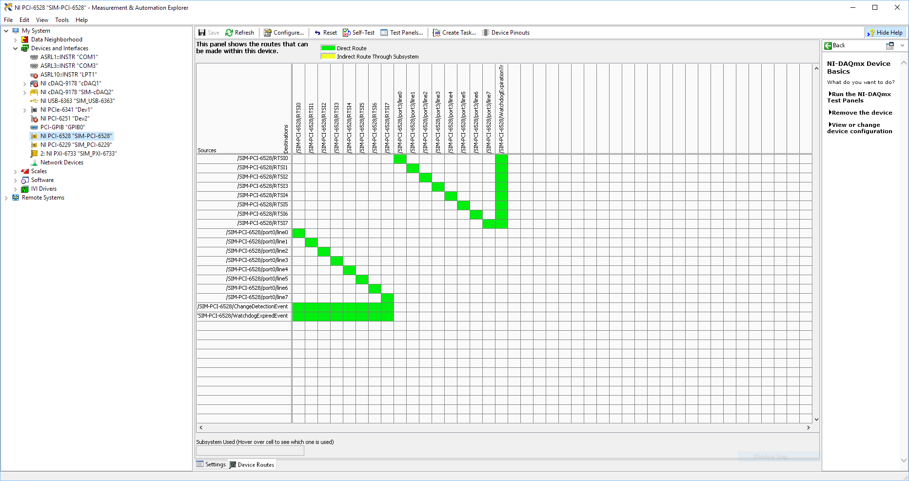
I use SMU 6612 card counter to measure the pulse width of the signals to PXI 6528 DIO card. These two cards are in the same chassis PXI (NI-SMU-1065). I could measure the pulse widths using the example LabVIEW 2013 Counter - pulse width of reading and (over) frequency example of .vi. However not all channels of the PXI-6528 map appear in the drop-down list of channels on the pulse width can be measured. Try to connect any other channel that those which are available in the drop-down list returns the error. On the PXI card port 6528 0,1 and 2 are entered ports and port 3-5 are output ports. I can measure the pulse on port 0, 3 width and line 0 port 1 and 4.
Can someone explain to me why don't see port 1 or port 2 channels in the drop-down list or force the VI to measure the width of pulse on these channels?
I can plug PXI-6528 external input channels SMU 6612 counter input channels and measure the pulse width, but if possible I'd like to avoid the external wiring between the 2 cards.
Probably not. Unless the routing plan is in fact reversed as it seems a bit sorta that. As stated on my system, you can route * of * a port of entry * to * RTSI, or you can route * of * RTSI * to * one output port. This does not make much sense to me, but that's what I see:
If the routing card * is * reversed, your only likely workaround without physical wire would be to generate impulses in question of port 3. It's pretty clear that 1,2,4,5-tetrachlorobenzene ports have no ability to interact with the bus timing, physical wiring would be the only option.
-Kevin P
-
I have observed 4132 PXI is sometimes load dependent. We were testing a specific device
which is part of the bi-directional and when we forced a current through the device in the negative sense of the whole
current is not available through a device (i.e.) when I force - 1mA through the device, I would see a 1mA through the device.
However what we observe, it's only 0.5mA is available through the device. This happens only in the negative sense.
2.) I have observed this behavior for a specific device. We tested the same device on keithley 2611 and they
measure well. In my view, that the problem must be with the EMS.
How much output impedance is present in this SMU? How can this problem be solved?
-
Acquire more than 2047 samples with the PXI-4461 instaled in SMU-1073
Hi all, I would ask you for help with the buffer limit.
I intend to buy digitizer PXI-4461 and he instal in SMU-1073 chassis, namely control via MXI Express of Labview installed on a separate computer.
What I need:
-to acquire data of a single channel of AI, but at least a sequence of 20 kS by a acquire task, in some situations until 200kS by a task to acquire.
The question:
- I can gain more than 2047 samples in a single sequence, like 200kS, with the PXI-4461 installed in SMU-1073?
Internal buffer of the PXI-4461 is reserved to 2047 samples. So I'm not sure if Labview can download remotely via MXI Express the data in the buffer of the PXI-4461 via MXI Express fast enough without any affection of the sampling program.
-in the case, this PXI-4461 with SMU-1073 isn't the right combination, what chassis and a controller can do?
Thanks much for the reply
Jan
It will work for you.
The on-board buffer 2047-sample is used only as a backup if the flow of data to the PC host (via MXI Express in this case) is not fast enough... that it will be (explained below). DAQmx transfers data from the buffer of the device to the host PC as fast as he can and, in ideal conditions, should not save the buffer 2047 much at all.
Let's just say you get 110 MB/s (randomly from a MXI data sheet) flow on your MXI connection. The 4461 has 2 analog inputs, which will be at 24 bits, we just round 32-bit in case it transfers the data in this way.
4 bytes/sample (32 bit) x 200,000 s/s x 2 (channels) = 1.6 MB/s, which is well below the 110 MB/s, which will make the MXI link.
clear as mud?
Germano-
-
Dear community,
I am trying to implement a background basket (software) PXI trigger on a chassis NI SMU-1082 with LabView 2015 (32-bit) running on an SMU-8135:
HS-DIO (SMU-6544) in slot 2,
-Acquisition of data (SMU-6363) into the Groove 4,
-Flex RIO (SMU-7962R + OR-6583) in the Groove 3.
The trigger schema is explained in the attached file ' LV-PXItrig-HSDIO-DAQ - overview.jpg ".
Scenario 1: written DAQ analog signal and sends signals trigger HS-DIO (software) through bottom of basket, after East of waveform of the complete signals to DAQ for acquisition.
Scenario 2: logical impulse on an external port HS-DIO triggers signals HS-DIO, after HS-DIO waveform is complete DAQ triggered for the acquisition of the ADC by the backplane.
In principle this breaks down to send a trigger of module A to B by PXI backplane. The SMU-1082 chassis has a bus trip with 8 lines (PXI_trigX, X = 0,..., 7) more a trigger in Star controlled the slot 2.
I've linked to implement a software trigger, but I can't access the refreshing resource and execution, see the attachment. Other ways of implementation including the DAQmx Terminal / routine disconnect Terminal have not worked for me either. I am aware about the connection of trigger using the node property VISA but I can't make a trigger.
Tips, comments or solutions are appreciated. Thank you!
For scenario 1, you want to trigger the HSDIO acquisition to begin as soon as the analog output DAQ starts? You can use
DAQmx Export Signalto send the trigger for the start of one of the lines from the Trig PXI backplane. Then, you need to configure your HSDIO acquisition to use a trigger digital beginning on the same line of trigger. Take a look at the example of the "Dynamic hardware generation start trigger" in the Finder of the example (help > find examples)For scenario 2, looks like you do a dynamic unit HSDIO generation when a digital trigger arrives on one of the PFI lines. Once the build is complete, you want to send a trigger for the DAQ hardware to begin sampling. If this is the case, you again use a trigger to start material in your task of NOR-HSDIO, as you did for scenario 1, but use external trig line as the source, rather than the bottom of basket. There is no case of material when the build is finished, but you can use a marker in script mode event instead. The example of the Generation with dynamic event marker' in the example Finder gives a good starting point for this type of operation. You'll want to set the output terminal for the event to be a line of backplane trig, and then tap the DAQmx to start on the same line trig trigger.
-
RF Mux PXI-2546 driver stops working when DAQ SMU-6259 is used.
Hi, I am experiencing a very strange thing. I have a system with two 1065 equipped chassis with about 15 different instruments.
It was working fine and has done for several years. Today the SMU-6363 DAQ crashed, I tried to replace it with a spare DAQ SMU-6259. I started with switching just the daq spare in but then the computer crashed every time during the installation of the pilot SMU-6259. So I thought that I need a driver update and installed DAQmx 15.1 (previous version was 14.5). It has not made any change. Computer always crashes constantly. Finally I found that if I remove the PXI - 2546 Rfmux in the SMU-6259 DAQ system will install and work properly. But now Rfmux PXI-2546 will not work when acquiring data SMU-6259 are installed on the system. I can get the Rfmux to work if I take the DAQ and vice versa.
Why is it like this and what can I do to solve?
I do not understand why a PXI-2546 Rfmux and an SMU-6259 DAQ interfere with one another.
/ Erik
Hi Anton, thanks for your answer!
Yes, it's very strange. I narrowed down it to these two devices. I got the blue screen during the installation of the Windows driver. So I tried first update the driver OR DAQmx. Who did not have any change.
Then I tried to roll back the NOR-DAQmx driver to a previous version. Crashes stopped then, but I could not both devices to work simultaneously. In the windows Device Manager, he showed a problem for the NI DAQ PXI-2546 peripheral device. I don't know why a mux is considered DAQ hardware either. The description of the problem says "some free resources". If I could get the Rf mux to work if I unplugged the daq and vice versa.
For the last two days, I was reinstall the system from scratch. I'm not done yet because it takes so much time to do this, but it seems to be ok now. But what a pain. I started with just the driver Rf Mux (Switch).
To do this I had to download almost 3 GB! For a 2 x 4 x 1 Mux driver. Then, the driver for the installed switch some NOR-DAQmx which I had to then update and download even more.
I think that NEITHER makes it very complicated with the pilot stuff. Instead of having these huge drivers packages which supposed to cover everything, it would be better with the smaller specific device drivers that could be easily found on the web under each device.
In any case I hope it should work ok now. I wonder what will happen when I get home my repaired SMU-6363. Should I plug it in or simply do not bother because I could face the same problem again?
/ Erik
-
PXI-4070 appearing does not in the locations of SMU-1075 16 & 17
Hello
I have an SMU-1075 with the help of a remote SMU-8370/PCIe-8371, 4 SMU-6363, SMU 8-2351 and PXI-4 4070 s. The PXI - 4070 s are required to be plugged into hybrid slots (2-5 or 15-18). To maximize throughput, the 4070 s are plugged into connectors 4 and 5 and the other 2 are plugged into the 16 & 17 slots so that the DMM is divided to the use of 2 different PCI to PCI bridges. The issue I see is that the 4070 s 2 plugged into slots 16 & 17 are not displayed in NI MAX and in the Device Manager, display an error (see photos). I can see and use all other modules in the chassis, including the other 4070 s 2.
I have 3 other machines running in production with a configuration almost identical, the only difference is that the other machines use a PCIe-8372(or maybe an old model of the PCIe-8371?) The main difference is that the cards in the older machines have 2 ports but the model # is not projected on the cards so 8372 is a guess based on the installation booklets) host controller. The PCs are identical in all 4 machines: industrial Advantech, WinXP sp3, Intel core 2 Quad, 2 GB of RAM.
If I remove the PCIe-8372 among the machines to work and install it in the machine, with that I have problems, I can see and use all of the 4070 s so that we know that the PXI chassis and 4070 s are very good. I also tried all sorts of versions of different drivers and drivers uninstalled/re-installed several times as well as the solution provided in this post of 2011: http://forums.ni.com/t5/PXI/PXI-4070-DMM-in-PXIe-1075-Chassis-not-found/m-p/1609804/highlight/true#M...
I was wondering if anyone else has had problems similar to this?
OR Support Reference #: 2292623
It's a strange problem. If anything, from the 2 to the guest card guest card 1 port should help. A few things...
Have you tried the 4070 s 2 Slots 16 and 17 of the 15 to 18 slots? One of the effects of different host maps is a different interrupt for some legacy interrupts swizzling, and their displacement that will put them on the other 2 lines. It seems unlikely that the problem.
Another long shot based on the differences between the PCIe-8372 and PCIe-8371: try to remove one of the panels of the SMU of the system. Reason: PCIe-8371 requires little storage space. If we put a needle with how the PC will provide then reduce the requirement will bring the use of net memory to 0 (PCIe-8371 ask 1 MB, which is the minimum no no one can ask any card PCIe/SMU).
Have you tried the software of BIOS compatibility and the switch on the PCIe-8371? http://www.NI.com/download/MXI-Express-BIOS-compatibility-software-1.5/3764/en/
-Robert
-
PXI-5154 making fried SMU-1075
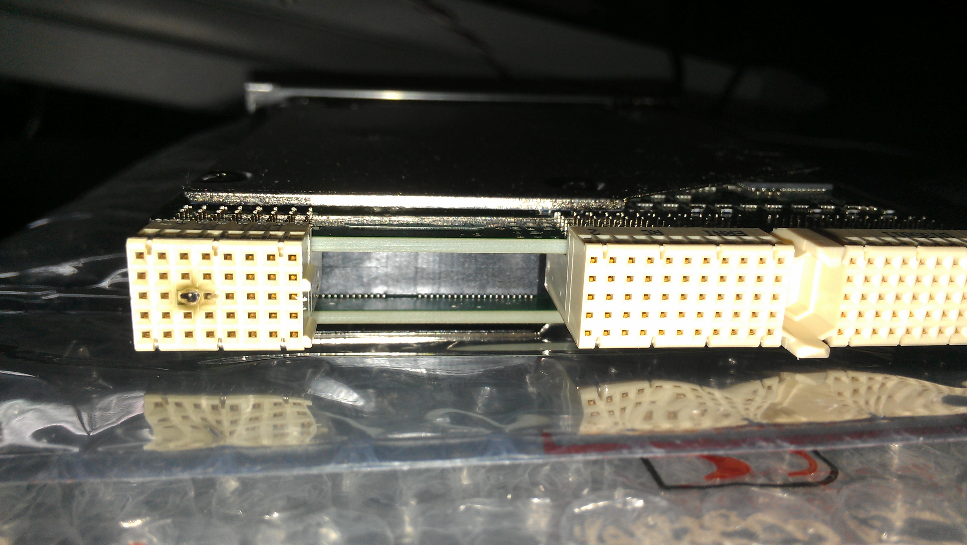
So, I just tried to install a PXI-5154 in SMU-1075 chassis. I followed the instructions that came with the card, but after turning on the chassis, there is no wizard detection of material, and no LED light came. I was going to try it in a different location, but when I slipped the card out of the chassis, I saw that looked burnt decision-making (see attached image). I'm not sure that I was wrong, and now I'm worried I might have damaged some of the other cards that have been installed in the chassis. So my question is double: 1) an idea of what went wrong here? 2.) nothing to say if the chassis itself is somewhat damaged? (3.) if the damage has not been caused by some error on my part of the user, is there an any warranty / replacement of the card?
Thank you
Well, turns out the instructions that came with the card were bad... the instructions say plug the card into a slot chassis marked with a number of cicrled, turns out I needed to plug the card into a slot with a number of cirled with a small 'H' beside him. Everything seems to be working fine now, thanks zeus
-
A PXI Module will work in a chassis/slots SMU
Simple question and the title says it all really. I'm 99% sure that it used because I do not know the connector backplane is different but thought I would ask for clarification.
Congratulations in advance.
Mitch
The connector backplane is totally different between PXI and SMU. However, most of the SMU chassis of NOR have hybrid slots that accept a card PXI or SMU.
-
PXI-6534 replacement by SMU-6537
I am currently ordering and receiving data from a device to measure with the PXI-6534, LabVIEW and DAQmx on Windows.
Can I replace the PXI-6534 by an SMU-6537 without having to change anything to my hardware (will be in other words, the cable connections and advice sheet be compatible)? If so, the code written to communicate to the PXI-6534 will be reusable with the SMU-6537?
Thank you comments or pointers.
X.
I'm really sorry, but I forgot to mention in my previous post that there is indeed an adapter that will allow you to use the same block that you used with the PXI-6534. You can find more info on this adapter cable on this link:
-
PXI-5114 can hold in the SMU 1085 chassis
MY company plan to purchase the chassis SMU 1085. But we also want to use PXI module: PXI-5114, PXI-5404, PXI-5406 and PXI-6723. The image on the Web site, say they cannot insert into the slot of the chassis SMU-1085 Hyberid? Is this true? I want to be clear on this before we buy.
Thank you
Hans
Hello Hans,.
Each of these modules is hybrid compatible. The devices are equipped with the small connector XJ4. One thing to note is that the PXI-5404 (778577-02) is the compatible version of the hybrid.
The page linked below deals with hybrid compatibility further in article 2.
PXI-5404 (778577 - 01).

Maybe you are looking for
-
How can I empty easily deleted folder?
I want to empty e-mail removed easily without doing it individually
-
On my XP, the option screen 'import' shows IE and Netscape/Mozilla as choice; on this Windows 7 computer, the only option is IE. Back on does not help, and the Firefox installation went well.
-
Satellite 1800-100 and SD-R6472
Hi all. I have a Satellite 1800-100 and I want to change the cd-rom included with a DVD - RW unit toshiba SD-R6472 drive, but then the BIOS not reconigze, shows "IDE #1 ERROR" and deactivates the device. That's happened? can I mount the new unit? I t
-
Starting problems on the Satellite Pro 4270
I have just received a satellite pro 4270 and told me it worked but when I turn it on all I get is a moon a cargo box that is not loading and a Sun I can here sounds of indoor work.
-
assassins creed 2, crashes every time in the same place
Hi, I was wondering if anyone has had similar problems with the game or is this just me, crashes every time in the same cut scene when leonardo is to map the fires for the flight mission, any help is much appreciated as its doing my head not being ab