DBL to I32
Hello
I would be grateful if someone could answer this question. Why 1 is divided by 2, the answer is 0 if the response uses the I32 data type? But 3 is divided by 2, the answer is 2 If the response uses the I32 data type? 5 is divided by 2, the answer is 2 If the response uses the I32 data type?
Thank you
Steve
As mentioned, rounded going to the even number nearest when X.5.
If you divide whole (and now with integers) numbers, you really should use the Quotient function & rest instead.
Tags: NI Software
Similar Questions
-
Show/hide multiple Button controls increment/decrement is AWOL
As far as I can see (LV 2013), there is a missing feature in LabVIEW, whereby, when you select multiple digital controls, you can't show/hide their increment/decrement buttons:
Here, I have 3 DBL, 1 I32 and 1 enum, but that goes for any combination of numeric values. If I right click on one of the selected controls, I have access to only two points in the title of the "visible Points":
-Label
-Legend
Where is ' Increment/decrement' part, whereas it is common to all these controls?
BUG? I couldn't find it mentioned elsewhere, but I would not be surprised to be the first to have noticed.
-
How can I keep the zeros before a value?
Hi guys

I'm afraid that it will be the first in a series of question that I fall into my first complex program. So far, I've only done small scale, but it is heavier.
The program will be a series of test for 10 circuits connected in 1 Panel. Each circuit have their own user serialnumber must enter in my program.
Serial number have a first letter (A = year 2010, B = year 2011 and so forth). After that, there is a five-digit number.
Example: A00001, A00002, A00003... etc.
Because there are 10 serialnumbers I would like that the user inputs the first serial number: A00001. Then my program automatically increments the serial number of 1 for each circuit. Given that the letter is changed each year I put it as text to the left of the digital control, if the user only need to enter "00001".
My program increment the serial number correctly and I can see the serial number for each circuit. The only problem is:
What I want to see:
User input: 00001
SN1: 00001
SN2: 00002
....
SN10: 00010
What I see:
User input: 00001 (turns into 1)
SN1: 1
SN2: 2
....
SN10: 10
LabVIEW removes my zeros to the left of the value. Ways to change this? I tried to change the DBL to i32 or u32. I only managed to get the zeros «,»
I could probably do any input string, but then I can't increment then user must enter 10 serialnumbers. Where I work, it is very important that the testcrew uses as few times as possible test.
Thank you and best regards,
Even
Just give Format string like '04D %' in numerical order-> advanced editing mode.
-Claude
-
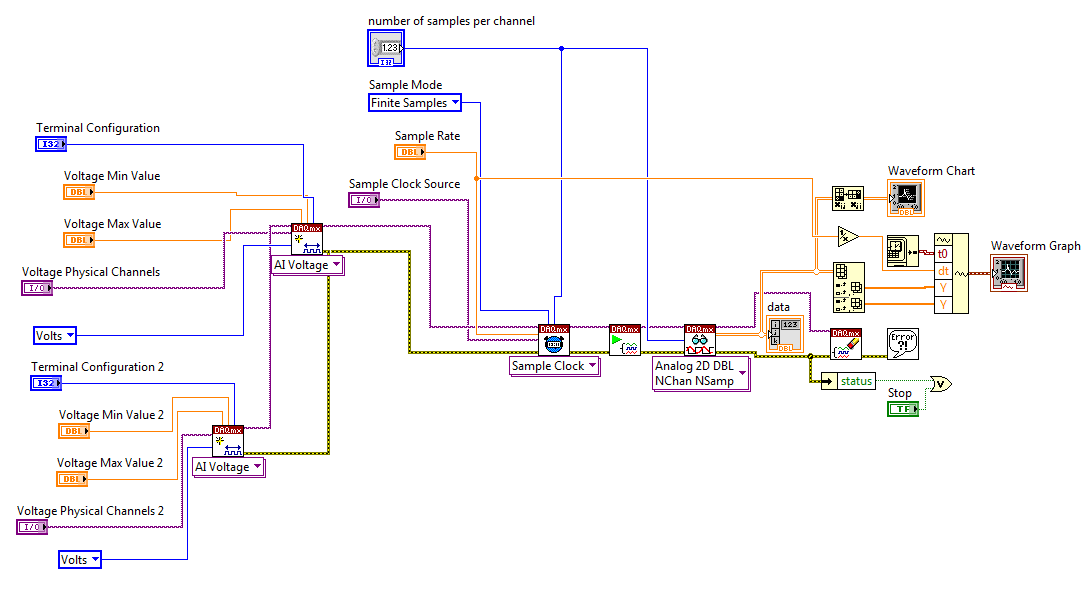
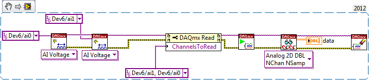
Order of the analogue channels 2D DBL NChan NSamp VI
The help file for the VI "Analog 2D NChan DBL NSamp" says that we can control the order of the vectors in the double 2D it creates by two ways:
(1) the order in which the strings are added to the task
(2) what is called the property of "playback channels.
I understand one, I think, and I can order strings like I want this way. However, I prefer to use the second option, so that if somehow the wiring of channel mixes, I can still have the channels in the order that I prefer.
Can someone help me understand how to do this please?
Thank you!
A little. The property of 'Playback channels' actually accepts a data type DAQmx Global Channel, even if you have a data type DAQmx task name. So the right way to use the property node DAQmx Read is to creat just a constant or control of the property 'ChannelsToRead' and entering the order the channels you want. I provide an excerpt from VI to help illustrate:
-
With a sampling of the data with DAQMX, error-200279 occurs when making 2d array dbl
Hello
I did a system of simple analog voltage with DAQMX data acquisition.
It is made for reading of capacitance, where output capacitance value out of a circuit in the periodic voltage signal.
What I want is to get data from four capacitors simultaneously through four channels, using samples n n (dbl 2d).
The structure of my VI is almost similar with examples of continuous sampling of voltage in LabView, with the exception of a few other calculations in the loop.
And for the synchronization of the trigger, I've corrected the edge of release with the external signal from the capacitance reading circuit.
Version no. 1 has a channel for data input voltage. Version n ° 2 has four channels for the input data.
While ver.1 can get accurate reading of four capacitors circuit data each (a single channel at a time),.
ver.2 acquires four channels of data, with a single thin data channel, all the others were wrong.
I saw a 200279 error occur in the DAQMX read part 2d dbl, so I tried increasing the buffers by changing the sampling frequency or the number of samples, but it wasn't everything.
I rose for most of the forums with the 200279 error, but the solution would not work on mine.
Anyone can find the problem? I will attach my screws it may include a bit of Korean language, but most of them are in English, shouldn't be too hard to recognize. Sorry for the inconvenience.
Oh I forgot, my DAQ is NI USB-6259, and it works in Win XP sp3 and LabView 8.6.
Thank you.
Hello Azurenight,
The 6259 is a DAQ card of the M Series Multiplexed, which means that it is not possible to sample each signal at the same instant, rather the channels are all sent through the ADC even and must be sampled in order. More information on this can be found here:
LabVIEW Help: Multiplexing compared with simultaneous sampling
http://zone.NI.com/reference/en-XX/help/370466W-01/mxcncpts/multisimulsamp/
It may still be possible to get the data you need with the card you have - could you give more information about the maximum eligible period between samples on different channels?
If you require * real * simultaneous sampling, you will probably need different hardware.
Kind regards
-
Another that the convenience of the format of the data acquired, are there benefits (e.g., memory, speed, etc.) usage
DAQmx readout 1 d Wfm NChan NSamp
-Or-
DAQmx read analog 2D DBL NChan NSamp
I'm a life-long in multiple buffer
channels using an architecture of producer/consumer. I am not concerned by information in absolute time available in the format of the wave form; It is convenient, but I can get what I need also. In post processing of the data, the format is a stack or face. If I collect the Wfm 1 d data I end up stripping to the Y-data for certain analyses, but eventually the construction of waveforms for the analysis of the other if I collect a given 2D DBL.-CTF
I did a quick comparative analysis and it seems that the WFM D 1 is slower and takes more memory than the 2D DBL. The overall impact of these differences depends on the size of your data blocks.
-
Convert the waveform (DBL) to a cluster of 2 elements
Hello
Can someone help me to convert the data type of waveform (DBL) to a cluster of 2 elements (X, Y). I found a few examples online, but I get an error when I wire everything together. I use VI of Tektronix to acquire a signal of channel 2 of my noculars, which I am able to do, but now I want to convert this data to a cluster so that I can use it for an existing application to acquisition. I have attached my VI version 8.2.
1Thanks
The is easy since it is part of the waveform data type. The X, you will need to calculate based on the dt by using a loop FOR.

-
Hello
Here, I have attached an example, similar code module is used in our project.
In this example in the control of two structures business SGL and U32 panels is directly related to the signpost DBL. If I give 4294967295(U32 value of maximum range in the case of forgery under the example) its display 4294967296.
Please give me the solution to show the correct value of U32 in signpost DBL.
Thank you
Wherry
In your code, 4294967295 is first converted to the SGL (on the edge of the box structure), then to the DBL. But this value may not be exactly converted SGL (due to lack of significant digits).
You should convert the SGL DBL value in the case of true.
-
1 table D of waveform DBL file or its
Hello.
I am building an application where I have an accelerometer with an interface USB-1208FS samples.
I have this loop on the inside with a few virtual instruments to display the waveform and frequency of it components. I tried many different approaches to record in a file, but it doesn't seem to work. No file is created even although I am administrator.
Data that are fed to the filters and these great are "table 1 d of waveform (DBL). Tried to convert other types of data, but does not work. This VI for example 'write waveform of File.VI' does nothing even if it should accept this type of data. It's "waveform table is a 1 d table the you want to write to a file of wave forms.»
I'd appreciate any help on my way to accomplish this task. With regard to Abraham
You still have not posted this VI. You say exactly what function and it is inside the loop / out of the loop that wants to say? My only guess is that you use the button stop in the toolbar.
-
Error-200524 occurred at .vi:2 DAQmx Write (analog 1-d NChan DBL 1Samp)
I'm trying to generate a signal to usb-6009 of simulated signal.
However, he keep poping errors:
Error-200524 occurred at .vi:2 DAQmx Write (analog 1-d NChan DBL 1Samp) if I choose "1 sample on request" in mx data acquisition.
If I have chaged to "continuous sample", the error has become
Error-200077 during the property Node DAQmx Timing (arg) 1 DAQmx Timing (sample clock) .vi:3-> 1.vi:Instance:0:1-> Untitled 1 Untitled. VI
Can someone could take care of my problem?
Very appreciate
The limitations of the analog output of your device is documented in the manual and has been considered on several occasions. Because it supports at the time of the application, you can only pass a single value to a moment, not a waveform. The timing is only the software and you can not generate a signal without a lot of jitter and the max frequency will be by the spec.
-
Hello
I have a problem during the conversion from my table.
I have a table 1 d of 32-bit integers for a long time.
I would like to convert a table 1 d of the 8-bit byte unsigned integers.
I try to use the conversion u8 block, but the result I get is a 1 d table that I accepted, but all my item values are transformed into zero rather than keep the original.
can someone help me?
Hi koekie,.
(1) you will have problems to convert I32 numbers greater than 255 (or smaller than 0) U8 values, both get forced to the U8 line possible!
(2) you don't say you are trying to convert the values.
(3) are you really want to convert your table instead of convert? What kind of result data do you really need?
-
USB-6008 LABVIEW 8.2. SINGLE CHANNEL WITH DBL INPUT VOLTAGE OUTPUT COMPARISON
I AM WRITING A PROGRAM THAT USES A SIMPLE USB-6008 ANALOG INPUT CHANNEL. I WANT TO READ CONTINUOUSLY THE VOLTAGE FOR 60 SECONDS. I WANT TO COMPARE A TENSION FOR THE PREVIOUS OF THIS SAME CHANNEL VOLTAGE, MAINLY FOR THE PERIOD OF TIME MAX VOLTAGE GIVEN, THEN GET A FINAL VOLTAGE READING. THE OUTPUT OF THE VI IS A DBL. I WANT ONLY TWO TENSIONS OF EXPORT TO EXCEL. TO SAVE TIME, I KNOW HOW TO EXPORT. CAN SOMEONE HELP ME WITH THIS ONE.
VI needs an register shift related to the Max & Min function. The current value would be the entrance is and the entrance of x is the left shift register. The max value gets wired for the shift register to the right. Don't forget to initialize it. The output of the shift register is the max you would write and the value of the DAQmx Read out of the loop of wire will give you the last reading.
Your waiting for 45 seconds makes no sense since you said that you wanted to read continuously. You also said that you wanted to read 60 seconds and all this logic is missing. A simple function of time elapsed, it's all you need.
-
Hello
I I32 table to display and I found nothing in Google. any expert here know if there is a way to display image I32?
I tried to use Fillimage to see if there's a way to work around, see attachment with the data table.
of the testDatadisplay.vi, I see that the value of Fillpixel change on the image, but I can't see pixel color change on the image, whatever the ColorFill I select.
take pixel [2.2] for an example:
It has original-(2^31) value (this is the value for all the background pixels outside the circle), I connect this value to the ComplexPixelValue
I want the value of-(2^31) be replaced on the image as the value of FillPixel, and I also want this pixel color to change to ColorFill.
That is to say, I want that the area outside the circle on a different color as in the example shown.
It seems that the value of FillPixel can change the mapping of the entire display, regardless of some ColorFill I choose.
It is the job of mapping how IMAQ display (on any database value and adjust the mapping)?
I chose the funaction Vi right to do this? or is it difficult to Labview?
If we cannot fill pixel color, which is the object of function colorpixel Fillimage?
Thanks for your time in advance.
XG
For the benefit of the users of the forum, this has been fixed in the following way:
Rather than using IMAQ and with regard to your data file an image file and the manipulation that we found it was easier to use a graph of the intensity and the graph have read the data file. By analyzing the chart, we have seen that the maximum value of the circle, IE the development of intensity, had a 317 value and the minimum value was 237. We were then able to associate this into 5 blocks of color from red to purple, panoramic the Rainbow. When we are separated from the Rainbow to the sections, we also found that the numerical value associated with each color. We were allowed to get the desired effect as your ideal image, with a rainbow texture image.
Then, we found that the value of the background would be just outside the boundary of the circle, then we have placed such as-238 and associated with the black color him. Then, we used a block of color that would be used to change the color of the background.
-
How .vi DAQmx Read (analog 2D NChan DBL NSamp) to acquire continuous data?
I try to get the .vi DAQmx Read (analog 2D NChan DBL NSamp) to acquire data continuously. The 'help' indicates I need to wire the number of samples per channel-1, but it doesn't seem to work for my application. If I have the wiring to any number greater than 0, the data collection works, but is not continuous. I enclose the code (Sept15_MainPanel_WorkingBaselines_ApplyBaselines and Calibration.vi) and a Subvi (Collect_Baselines.vi) if someone wants to take a look.
Here's what I'm trying to do:
I use a unit NI USB-6009 to collect analog voltages of load cells 2 (channel 0 and channel 1) and 2 displacement transducers (channel 2 and 3). The main panel of the VI contains a listbox with 4 options - 'Check EMG channel', "Collect base lines," "Collect Data" and "end of program". 'Collect base lines' 'End of program' work and I'm working on writing code to "Collect data".
For the option "Basic collection", 2500 samples are read from 4 channels described above and 2500 samples are averaged. This works.
The option "Data collection" - I would like to that data from 4 channels to acquire permanently. Finally, for the option of data collection, data acquisition stops when channel 0 detects the force of 200 N - so I will not always have a finite number of samples read. The time it takes to reach the value of this force will be different for each test.
-How can I get continuous samples for my 4 channel? Is .vi DAQmx Read (analog 2D NChan DBL NSamp) function badly and if yes, what should I use?
Thanks in advance for any ideas or advice.
Esther
First, in case 1, you need not the structure of flat sequence. The son of the error and data properly will dictate the flow of execution. Then, in State 2, you must initialize the shift register, unless you want to keep the data is accumulated each time that you run the vi. The reason why you don't see all the data here is because you have - 1 wired for the number of samples per input channel. You must connect a number here, even if you are taking continuous samples. The service needs to know how much sample to gather at one time. If you put-1 here, the number of samples per channel must be set up in the synchronization function DAQmx (sample clock). If you specify a number here, then you put-1 in playback function. The DAQ hardware will read continuously, you must retrieve the data from time to time, so you must specify the number of samples. By reading inside a loop, it will continue to read until the stop function is encountered. I guess that the Clear function acts as a stop. But you must always indicate playback vi how many samples to read and return on each iteration of the loop.
The documentation is a little misleading. He warns that a - 1 will cause a continuous reading. But the pads are so big, he can not read continuously forever without losing data. If you specify a finite number, playback in a loop, and he will read this number and return the data (empty the internal buffer) at each iteration of the loop. Continuous means that you just call the start function once. He will read at each iteration of the loop until the stop function (or clear) is called.
Here is the difference between the setting of the Timing DAQmx function for continuous or finished reading: finite samples requires a tenure, he reads the finite number of samples, and it's done. It requires another start to read more data. Continues to read requires only a start. It still reads a finite number of samples, but when this is done, you can retrieve the data by calling the read function until he could continue. After the reading, you don't have to call for new start. Look at it this way. Start is what starts the collection of data, not the read function. Just read empty buffers in your data feed. The data acquisition continues in continuous mode, but you must call read again to get the data on the pads. If you specify basically buffer size when you set the number of samples per channel.
-
Conversion of 3 bytes in an I32
I have 3 U8 bytes in a table (a byte received 24 bit number). How can I convert them to compliment of 2 number of I32 for general use?
I wanted to do a .vi I can get value in addition to 2 from content to any position in an array of U8. My problem is that I have a byte stream that feeds coded values that can be 32-bit, 24-bit or 16-bit in size. I wish I could get out somehow the parameter "type" to make it really versatile. Do you know any VI that already do this?
I may even face values of odd size as 10bits!
Thank you very much for the solution simplified. I can just go with a code tailored to each type of extraction that I need to do easier.
I'm starting to see parallels with C. Although I still think that a shift would be useful. As much as the Type cast operator ideally positions the value it reads his entry, at the upper end of the 32-bit value.
Thanks again.
Maybe you are looking for
-
I have a suggestion for you it is the photos application, there is no security for the recently deleted photos. If someone knows the password of the Iphone they can delete the photos and also remove photos recently deleted, if there is need code rest
-
Satellite P100-286 - charge not completely even in stop...
Hey all,. I have a Toshiba Satellite P100-286 and my problem is that when it s on and I plugged it load the light orange will be on indicating that the load and it will say connected load, but the battery life does not exceed 96%, yesterday he wouldn
-
Computer runs slowly, and indicates that there is a high use of the disk of Norton.
Original title: dell inspiron 1545 Why a box showing me I have high use of norton disc and my computer is running slowly I thank you for any idea.
-
APEX 5.0.2/Oracle 11.1As Patrick Wolf-Oracle on his blog, two additional parameters must be added to OHS dads.conf allowing the APEX to serve static files. Before adding these parameters, the emitted HTML code has been"< script type =" text/javascrip
-
I used this function several times and cannot understand why he is now grayed out. I have a journal of GPX track loaded and selected images with times that must match but no functionality available Auto-Tag. Any help appreciated.