Definition of series R Analog Input Mode programmatic
Hello
I understand that the mode setting of analog input for 7854R series card can be made through the project manager (RIO Device setup)
I would like to know if there is anyway we can do programmatically (as in the case of some cRIO modules HAVE).
Thanks in advance for the help!
Hey,.
No, you can not change programmatically. Right under the RIO device installation program.
Christian
Tags: NI Hardware
Similar Questions
-
How to read the analog inputs of one Board of R for (PXI-7851R) series
You can guide me please with the steps for reading of the analog inputs of a series a. card I use as the target fpga PXI-7851R.
Have you looked at the examples provided with LabVIEW? There are examples showing how to read the analog inputs.
-
Hi all
I'm starting my first app using a card of RIO for the analog input and power (two PCI-7833).
My previous experience with DAQ systems was on PC so I'm especially familiar with DAQmx. It is my understanding that DAQmx is not really being used on these boards, there is no DAQmx tasks to play with.
So, my question is this: How can I dynamically set the range of the signal of the analog inputs so that I get the best possible resolution?
What I want to say in DAQmx if I know that the input signal is only 1 V pk to pk I can put this beforehand in the task.
Thank you!
OK, a little further digging shows the input range is set to +/-10V, is this correct?
-
How to read the NI 9201 Module lab mode analog input signal
Hi all
IAM using the module Crio-9012 real-time controller
ND iam using NOR-9201 for entry and exit of NI9263 for
I have configures cRIO 9012 on my Pc
But how I'll take analog input using the module NOR-9201
Thank you
TC
Hello
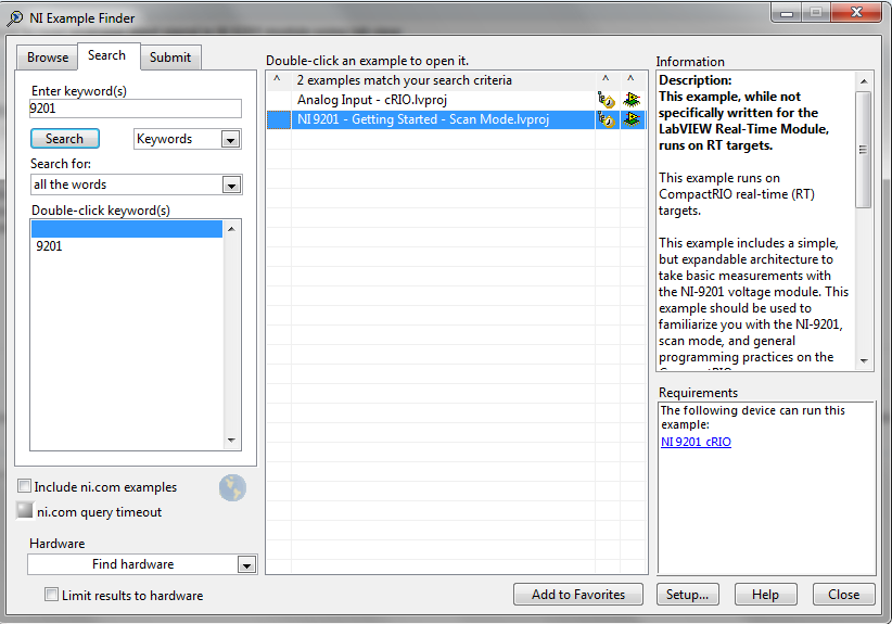
I recommend you take a look at the following examples in the example Finder LabVIEW. If you go to help--> find examples, you will see this window. Just search 9201 and you will see 2 examples:
I hope this helps!
-
[fpga] Configuration of analog input or 7965R
Hi all
I have a card FPGA NI FlexRIO (SMU-7965R) with an adaptation module (NI 5733). I'm using Labview real-time 2012. My measurements are dominated with harmonic sound of 60 Hz, which is most likely due to the ground loop. I try to put my analog inputs (as opposed to the CSR, NRSE) differnetial mode to try to overcome the ground loop. I came across this link which explains how to configure the FPGA input channels-
http://digital.NI.com/public.nsf/allkb/08EF26D2E9041BC6862570E0001E442E
However, the installation program of the RIO device for my goal of opening, I found that there is no option to choose the channel configuration (as shown in the attached picture). This means that the analog channels are in differential mode by default? If this is not the case, how can I change?
Any help will be greatly appreciated.
Hello!
This KB is in what regards R, not FlexRIO product line series materials. I know it's a little confusing because the 7965 has an indicator of 'R' at the end of the model name, but the R simply it is a product with an FPGA that is programmable by the user.
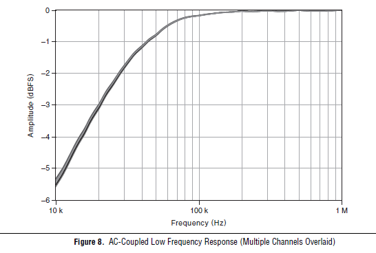
Unfortunately, the adaptation modules FlexRIO 573 x are all only ended then we will not be able to change to the differential. What is the frequency of the signal you're trying to measure? Another option would be to set the 5733 coupling AC mode, which would give the frequency response following, dramatically eliminating any sound below 10 kHz.
-
analog input PCI-6251, implemented
Hi all
Can I set the analog inputs of the PCI-6251 in configuration of mix (some in differential mode) and others in single ended mode. Because in my set up the differential option is grayed out.
Thank you
dphan128
Yes, you should be able to do. You have 16 analog inputs. Differential, you will use two of them per channel. See the manual of series DAQ M. you can program channels on a M Series device to acquire with different
reference to the ground. To allow m
ultimode sweep in LabVIEW, use OR-DAQmx create
Virtual channel.VI of the API OR-DAQmx. You must use a new VI for
each channel or group of channels configured in another mode of entry.
Don't forget that for a premium that you would for example wire HAVE 0 to the + side and AI 8 - side. So now you can not use the AI 8 for simple nerve. HAVE 1 corresponds to the AI 9 etc. until 7 AM, GOT 16.
I hope this helps.
-
What is the analog input of the NI PCI-6229 impedance?
I am trying to determine the effect of a 12 K resistor that is in series with an analog input of an NI PCI-6229 data acquisition card. Resistance of 12K seems to be part of a RC filter. I have a 0-10 VDC source this supply circuit. What is the impedance of the analog input of the NI PCI-6229 data acquisition card? If it makes any difference, the analog input is connected in differential mode with a 180K resistor to Gnd AI.
Thank you
RWB
Hi, RWB,.
The input impedance is classified in the specifications 10 GOhm. So, the effect of your k 12 resistance should be relatively low. Take care!
-
How to compare analog input signals?
Hi all
I use PCIe6363 DAQ to collect the analog input signals. Mode of input signal is continuous and single channel several example. The sampling frequency is 2 ms/s, number of sample 100KS or less. This means DAQ 100KS of collect and draw a line/curve. I want to compare the two curves. The problem is DAQ continuously collects data and plot also continuously. Would you please is it possible to compare the curves of this operation continuous operation. The main goal is to justify whether or not the signal of incomeing maintain consistency.
Thank you very much
Azim
You can store a waveform in a shift register. Then you have in memory compared to the new waveform.
-
Several analog inputs seem to change any of the other (details DAQ: 2120 BNC and 6062E)
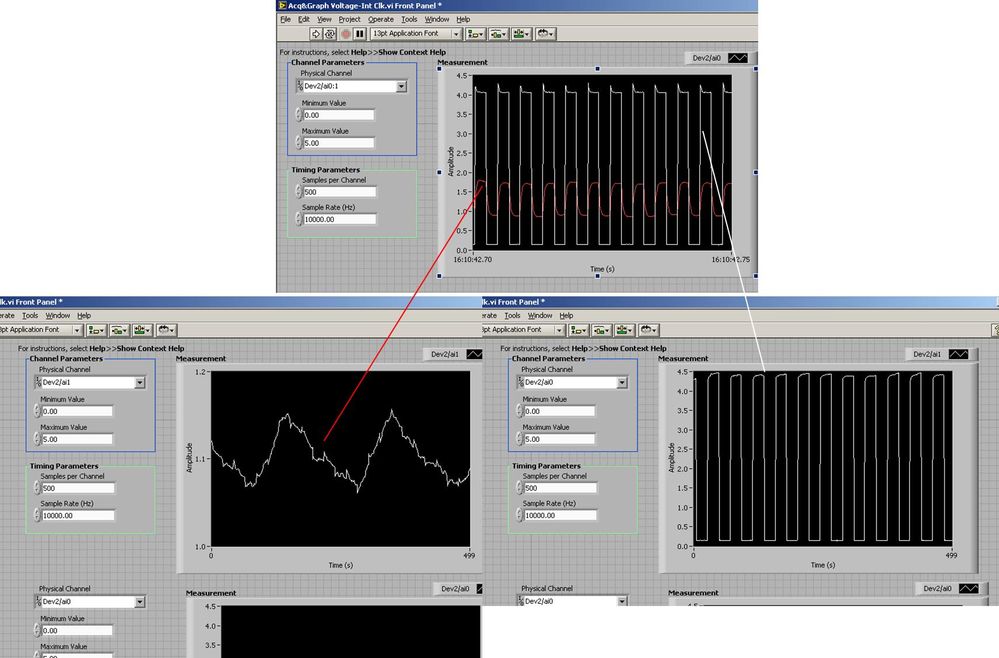
I use the BNC 2120 DAQ board connected to the data acquisition card 6062E to record two analog inputs. An entry is connected to ai0 and the other at ai1. Example vi: "Acq & graph int clk tension" has been used to measure the two entries with the value read NChan NSamp vi (channels being dev2 / ai0:1). The output is the top graph in the image. However, this seemed a bit strange to me that one of them should be modulating with a different frequency. When I record both entered individually (two in low pictures) they are indeed different since the entries shown in the top graph.

Why this would be the case, and how can I overcome this to measure the real signals?
Thank you!
The E series card takes the samples as soon as possible. Thus, for example,.
If you have 16 analog input channels but you only read of
channel 0 and 1, the map will show the channels 0 and 1 right
After and then wait 14 'ticks '. What's that little run-in
the origin of the afterglow.
I think you can get the card to wait a certain
number of ticks with a property node. I have attached a screenshot. You
can find the property node in the palette of functions >
Measurement of e/s > NOR-DAQmx > node Timing. Expand it
Property node so there's two entrances. The properties are in
Left click on the node and going more > converted >
Its properties delay units and sampling clock delay and delay that
you want.If the phase is important so the above is not the best
the option because it causes a delay in phase. So, if you need true simultaneous
sampling, then you will need different hardware. The S series is everything
simultaneous sampling.Or, rather than the Delay property and delay units, try the Rate property
find more > converted > rate.If this is not
work either, you can move the second signal source to, say, AI8 and
Connect everyone to the ground. Readings for these, but just do not take into account
the data. In this way the ADC will sag to the ground at the time where that can happen
the second string in the way so that you should not see this frequency
ghosting on the other channel. -
Hello
The data entry in LabVIEW by my USB-1208LS is accurate, but the analog input voltage values are quantified (there are only a few repeating values: 0,691 0.696 0,701 0.696 0,701 0,691 0,691 0,691, etc..). I am able the tensions of four photocells, propelled by the + 5V of USB-1208LS. Each cell is measured in a different channel using the differential input mode. Is it possible to fix the quantification of data?
I don't know if it's a problem of LabVIEW, but attached is my diagram, in the cases where I'm not seized the tension properly.
Thank you in advance.
On the input range, the resolution of this device is about 5 +/-10 V mV, which is exactly what you see. The resolution is established by calculating the length of the total voltage range (20 V) and dividing by the number of steps or bins the A/D converter on this beach (2 ^ 12 = 4096). Yes, resolution = 20/4096 = 4.883 mV.
To get the best resolution, you will need to use a smaller range (if your signal wil fits into a smaller range) or get a DAQ hardware with a higher resolution, for example a 16-bit converter, or 24-bit.
Lynn
-
USB-6211: analog input signal affecting another of the same map AI
Hello
I use the DAQ-nor-6211 map and DAQmx features to read a hammer and a signal of the accelerometer and then use other LabView functions to make the FFT of these analog input signals. However, it seems that the analog inputs where the hammer and the accelerometer are connected generate a kind of noise or influence in other entries of this data that is not connected to any other sensor acquisition board.
I've had different experiences in order to check if the problem is with reading the card: put the accelerometer and hit the dog in another table where the DAQ card table was located (to avoid the vibrations on the map and a possible noise), ai1 entry was logged on the differential mode on the dog and the ai4 of entry is connected to the output (z axis) of the accelerometer. The other 2 ai2 and ai3, entries that can also be read by my LabView program, are open (i. e., any other sensor is connected to the card). When the structure where the accelerometer is located is struck by the hammer, the signal of ai2 ("x axis" seen in the first attached document) has a curve (on the time domain) which initialize almost at the same time that the hammer and the a3 of entry has a weak signal, but with the swing as well as the signal of ai4. The document "hammer ai1 + z_axis connected_ _x_axis disconnected ai2 + y_axis ai3 ai4" images that I captured the chart created in LabView. On these graphs, it is possible to check on the FFT the ai3 signal and ai4 has the same behavior (with different intensities), and enlarged figure of time domain image, we can see that the signal of ai2 increase almost at the same time of the signal of the hammer (ai1). The signal picked up by the sensors are probably creating a sort of noise on open entries ai2 and ai3.
Another experiment was conducted to check if the signal from a single entry that may affect the signal read from each other near the entrances: the DAQmx task Create channel had a physical channel has changed: ai3 entry has been modified by ai7 (maintain the same connection mode: differential), and the results are visible on the second attached document. In the graphs obtained in this experiment, it seems that the entrance of the hammer (ai1) affects the signal of input ai2 and ai7, which are not connected. And the ai4 signal does not seem to influence the other inputs, because he has a different curve on the graph of the FFT.
The same experiment was conducted using the CSR connection (change threads and create the DAQmx Channel Configuration), but the results were the same as those found using differential connection.
Finally, if the output of the accelerometer is connected on the ai2, the signal of the other open entries ai4 and ai7 seem to be affected by the signal of the accelerometer on ai2 (last document attached).
Could you tell me if the problem I encounter is caused by the DAQ card with this information that I gave to you? And if the answer is Yes, do you know if there is a way to avoid this noise create in one entry on the other hand, it please?
Thank you
Maybe Ghosting or crosstalk? Just an idea.
-
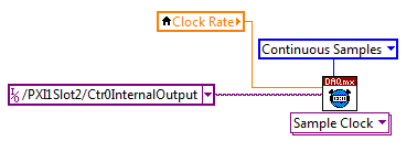
Continually acquire analog input, internal clock, break, Multiple device
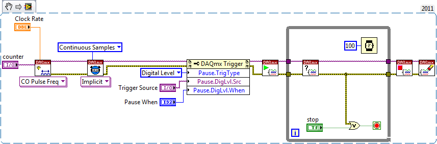
I have a PXI chassis with 6 cards SMU-6363. I want to acquire data on the channels of each SMU-6363 map continuous AI, using the internal clock for timing. I need to use a trigger to pause reading of a DI on one of the cards SMU-6363 for a break and to reactivate the acquisition. I came across this example: https://decibel.ni.com/content/docs/DOC-12256/ , but keep getting error-201019 DAQmx start task "trigger break is not supported in a task to more devices. To configure the start of break in a multi-device configuration, you must use no more than one device per task and route manually clock in demand signals. »
The problem is that the configuration of I is made during execution by the operator. Sometimes they want to acquire data on one HERE through all 6 cards SMU-6363, sometimes they want to acquire data on each channel of AI through all 6 cards SMU-6363. What makes the task definition until manually route clock signals between devices for each rather difficult task.
Is there a simpler way to solve this problem?
Set a task to output counter - something like this:
Next, configure your task of analog input to use the sample clock output of the meter:
Best regards
-
I use an analog input on a PCI-6224 and are having problems with the clock source
I use an analog input on a PCI-6224 and are having problems with the clock source. I'm trying samples of 16 different analog inputs very quickly. I have the sample mode: Timed Single Point material. The rate, that I am running is the maximum (250 kHz (15625Hz per channel)). I left the default clock source and trying to taste several times. The analogue input works for a short time (2-3 seconds) and then everything stops. I'm doing something wrong or is there something I'm missing? Any advice would be great.
That's how you samples using the sample clock clock. If you see a delay then something is wrong with how you track/data visualization.
Single point NI the hardware is for PID control with a real-time operating system.
-
NI USB - 6212 BNC analog input impedance matching
I just ordered a case NOR USB - 6212 BNC DAQ (should be delivered soon). I want to use to measure HV signals using a probe of high voltage of 1/1000 I have.
Now, datasheet of the probe (not a lot of info) says it has an impedance imput 100MOhm. I suppose that it consists of a simple resisitve divider, and if the ratio is 1/1000, I wait so to have a 99.9MOhm resistance in series with a 0.1MOhm resistance. However, the data sheet also specify that the probe is designed to be connected to an oscilloscope with an impedance of 1MOhm. As this input impedance is very low compared to the low value of the separator of resistance resistance, so I guess that the real resistance at the level of the sensor values 99.9MOhm and 0.11MOhm (to obtain the 0.99 and 0.1MOhm when it is connected to the oscilloscope for 1mW).
Therefore, given that the impedance of the USB-6212 according to the datasheet, the analog input is > 10GOhm, I expect to measure higher to true alternative voltages when connected to the acquisition of data from 10%. This assumption has a meaning?
What would be the best way to get around this? Do a calibration and correct the values acquired in LabVIEW code? Or should I add precision 1MOhm resistance at the same time to the acquisition of input data to decrease its resistance to entry to the value expected by the probe?
Thanks for your help!
Since you have a range of 1000: 1 I guess you also need bandwidth (I have a TEK 6015 A
 ), so you need based on the impedance input, a complex value, means he must not only watch but also the ability to input resistance (1 M). demarcation of the field probes have usually some elements of toppings to match the probe and the input scope. RTFM of the help of the probe
BUT a more serious point is that with your probe, you have a very high resistance. And if you look in the specification of the 6212 you will find on page 2 by mistake ppm in logarithmic scale graph! and even 100 k source impedance it not shown.
So I'm afraid that a simple 1 M on the DAQ entry can work if you're only measuring DC, and only if you use a channel on the acquisition of data. A workaround is an amplifier separate buffer with an impedance of good entry corresponding to the specification of your probe and a low output impedance.
-
Hello
I must acquire Differential (8) and NRSE (16) of the analog inputs with an SMU-6363. I'm confused, what kind of configuration in the program labview is necessary to achieve usage OR daqmx live I enclose two modes of configuration of blockdiagrams that could match my need. Kindly help me which one is configured correctly
Thanks and greetings
Naveen
The background a type2 seems correct.
Maybe you are looking for
-
synchronization between the iphone and windows 7
Can I synchronize excel and word between iphone and windows 7? How? CAN I get excel and word or compatible programs (aps) on iphone? Also - I have an old version of MS Outlook (2002, 10.6 V, SP3) I want to be able to sync with the calendar on the
-
Hello. IBought my IPhone of the Korea. I lost my Iphone 5. But I don't have the IMEI number. You can help me find my IMEI number
-
Hello I am trying to find a way to calculate the exponential matrix on the 50 g. Given A [[3 0 0.0 2 1.0 0 2]] Result (exp(t*A)): [[exp3t exp2t 0.0 0 t * exp2t, 0 exp2t 0]] What I've tried so far: DIAGMAP (http://goo.gl/12ZruS) -> diagonalizable matr
-
Now my screen has a blue tint and when you start the screen is not black and blue
-
I can print pictures in color with my HP8600 but all the text - no matter of what color is selected - print in black. I just changed all color cartridges. They are all HP cartridges. The parameters are high quality grayscale and printing all black