FPGA: stream of compilation
Recently, after you add a code over to the FPGA design, I systematically get the message "this is a problem with the stream of compilation. The compilation will continue, but reports of compilation will be unavailable until it is complete." This message to 15-40 minutes after the start of the compilation, and before the use of the device about the report is available.
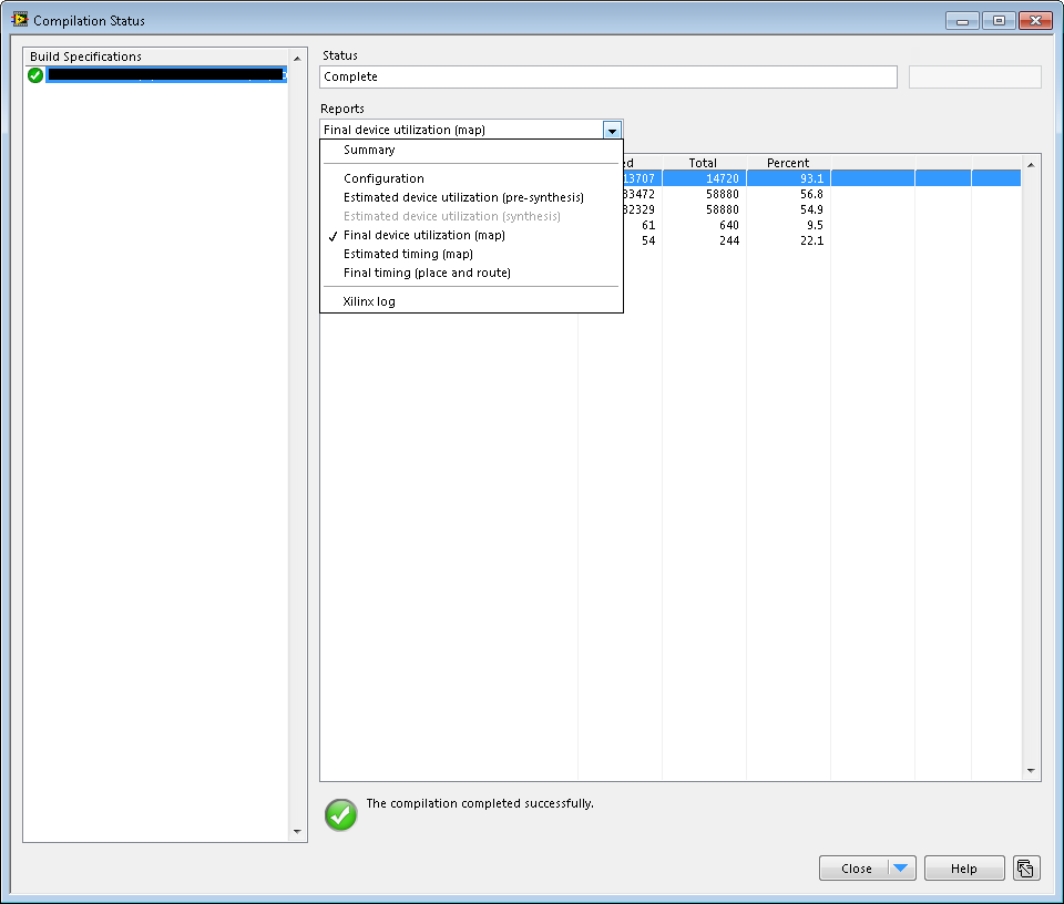
As the message says, the compilation continues, but when it finishes the estimated use of device is not available. See screenshots.
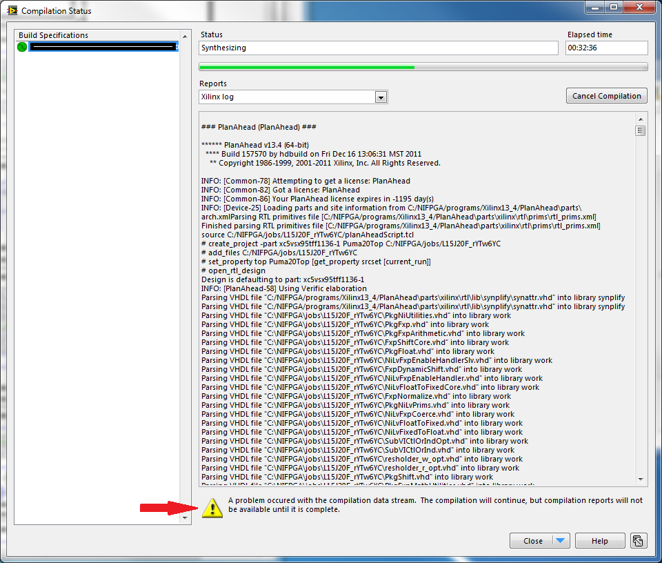
It's annoying, because the compilation takes about 2 hours and based on the ratio of estimated calendar I could decide to cancel the compilation or let it run. The design is quite the limit regarding schedules, we code running at 200 MHz and the compilation fails about 50% of the time due to timing violations. Now that I don't see the report estimated calendar, I always wait the full 2 hours.
Any ideas or suggestions?
LV2012 SP1 with Xilinx tools using 13.4 on a map SMU-7965R.
Hey Dan,
In fact, it is a Bug in this version. It has been fixed in versions of follow-up.
So in order to see your device using estimated, that you must update your fpga and Labview module.
Or you are trying to optimize your code. When it does turn on the edge, so that this problem does not arise, I guess.
Here the documentation on the code optimization:
Optimization of your screws of LabVIEW FPGA: running in parallel and Pipelining
http://www.NI.com/white-paper/3749/en/
Best regards, Elli
Tags: NI Software
Similar Questions
-
I'm new to LabView FPGA and am currently trying to compile my VI on the target FPGA (an NI PXI-7842R).
The initial phase (what seems like Labview generating the VHDL code) appears to run successfully.
The next step (which seems to be the actual compilation on the FPGA) runs for a short time, and then reports an error at the end of the phase of PlanAhead.
The error message says:
LabVIEW FPGA: An internal software error in the worker of compilation occurred.
Error-61330 occurred at niFpgaCompileWorker_ProcessStatusPipe.vi:640001<><>
Possible reasons:
LabVIEW FPGA: An internal software error in the worker of compilation occurred.
Access to the path 'D:\NIFPGA\corecache\F70DE3619E4B4D193B01053C274FD022E0C94A19.timestamp' is denied.
Any thoughts?
I use 2013 LabView, the module 2013 FPGA and Xilinx tools 14.4 on Windows XP SP3.
-
FPGA connect for compiling the server
Hi all
I'm just trying to write my code for my Spartan 3 FPGA. I was moved to another computer so I tried to install the right tools... LabView 2010, the module, LabView FPGA 2010 so that the pilot of the Commission of the Spartan Xlinix I use. Windows XP (32 bit)
Everything seems functional until the moment when I try to compile the code on my device. Apparently it "impossible to connect to the build server" or "compilation tools are not installed on this computer." I thought that all that is necessary to compile is included in the download of the module.
Is there some piece of obivous I'm missing? Thanks in advance.
Hi Oli,
I had the same problem recently. It is very important that all the good software and drivers are installed in the order so that everything works as expected. Looks like you have installed the driver appropriate for the Xilinx Board, you may not have Compilation of Xilinx tools for your FPGA. For the Spartan 3 FPGA, I recommend that you download Xilinx tools 12.4. This will allow your computer to compile the FPGA bitfiles for your specific FPGA module.
Kind regards
-
FPGA timing when compiling PID loop error
Hello.
I'm using Labview 2011 card FPGA PCI-7833R.
My problem is that whenever I try to integrate FPGA designed screws in my code, I get an error of timing. See the photos displayed below.
In this case, I have an express VI PID which I use in a used while loop (not even timed!) in my FPGA code, but when compiling, I get an error saying that the possible maximum clock frequency is the 43 MHz.
I have a lot of loops, a few running at 80 MHz. Is there a way to slow down a specific while loop, so that it runs at 40 MHz and not 80 MHz, as others? The compiler does not seem to meet the simple addition of a timer loop...
Thank you
Orel.
PS the same thing happens when I try to add a lowpass filter VI of the FPGA code.
Is it possible that you set the level above 80 Mhz clock? This is what it looks like to me. In Explorer, right click on the FPGA target, select Properties, then go to the category "first level clock.
-
LabVIEW FPGA CLIP node compilation error
Hello NO,.
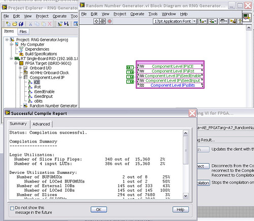
I work on an application for my Single-Board RIO (sbRIO-9601) and faced with a compile error when I try to compile my FPGA personality via the ELEMENT node. I have two .vhd files that I declare in my .xml file and all at this point works great. I add the IP-level component to my project and then drag it to the VI I created under my FPGA.
Within the FPGA personality, I essentially have to add some constants on the indicators and entries CLIP to my CLIP out and attempt to save/compile. With this simple configuration, I met a compilation error (ERROR: MapLib:820 - symbol LUT4... see report filling for details on which signals were cut). If I go back to my VI and delete indicators on the output (making the output pin of the CLIP connected to nothing), compiles fine.
I've included screenshots, VHDL and LV project files. What could be causing an indicator of the output of my VI to force compilation errors?
Otherwise that it is attached to the output ELEMENT, a successful compilation...
After that the output indicator comes with CLIP, compilation to fail...

NEITHER sbRIO-9601
LabVIEW 8.6.0
LabVIEW FPGA
Windows XP (32-bit, English)
No conflicting background process (not Google desktop, etc.).Usually a "trimming" error gives to think that there are a few missing IP. Often, a CLIP source file is missing or the path specified in the XML file is incorrect.
In your case I believe that there is an error in the XML declaration:
1.0
RandomNumberGenerator
urng_n11213_w36dp_t4_p89.vhd
fifo2.vhd
This indicates LV FPGA to expect a higher level entity called "RandomNumberGenerator" defined in one of two VHDL files. However, I couldn't see this entity in one of two files. If urng_n11213_w36dp_t4_p89 is the top-level entity, edit the XML to instead set the HDLName tag as follows:
urng_n11213_w36dp_t4_p89 Also - in your XML, you set the 'oBits' music VIDEO for output as a U32, however the VHDL port is defined as a vector of bits 89:
oBits: out std_logic_vector (89-1 downto 0)
These definitions must match and the maximum size of the vector CLIP IO is 32, so you have to break your oBits in three exits U32 output. I have added the ports and changed your logic of assignment as follows:
oBits1(31 downto 0)<= srcs(31="" downto="">
oBits2(31 downto 0)<= srcs(63="" downto="">
oBits3(31 downto 0)<= "0000000"="" &="" srcs(88="" downto="">Both of these changes resulted in a successful compilation.
Note: The only compiler errors when you add the flag because otherwise your CUTTING code is optimized design. If the IP is instantiated in a design, but nothing is connected to its output, it consumes all logic? Most of the time the FPGA compiler is smart enough to get it out.
-
LabVIEW FPGA Module 2015 Compilation to PXIe7820 with 'no timetable '.
I did a first compilation for the SMU with the Xilinx Vivado 2014.4 tool 7820 (64-bit). Compilation report said.
Compilation successfully completed.
Use of the device
---------------------------
Total bands: 19.1% (25350 4848)
Records of slice: 6.9% (13937 on 202800)
Slice lUTs: 12.3% (101400 12430)
Block of Rams: 0.9% (3 out of 325)
DSP48s: 6.2% (37 out of 600)Calendar
---------------------------
None.Compile time
---------------------------
Introduction date: 16.07.2016 12:48
Date recovered results: 16.07.2016 12:59
Waiting time in the queue: 00:08
Compilation of time: 10:16
-Generate a Xilinx IP: 00:00
-Summarize - Vivado: 04:18
-Optimize the logic: 00:14
-Place: 01:17
-Optimize the Timing: 00:18
-Road: 03:04
"- Generate the programming file: 00:56.This means no timetable? The embedded clock's 40 MHz. It runs with this clock? Beacause 7833 compilations for the pci or pcie 7842 report displays the maximum clock time.
Hello
"none" means simply from what I can understand, that there is no violation of timing. The source of synchronization that will be used is (as you have already suspected it) on-board 40 MHz clock.
As to why you don't get a mention of the MiteClk and the ReliableClk in summary, I think that it is due the 7833 and the 7842 relying on FPGA Virtex-II and Virtex-5, while the 7820 uses the Kintex-7 family. Depending on what type FPGA using different estimates regarding the use of the device and synchronization are not always available.
As I said, as long as you don't get not an error of timing and your compilation is completed successfully, you should be fine.
Kind regards
Alex
-
FPGA LabVIEW 2011 Compilation Crash - i/o node
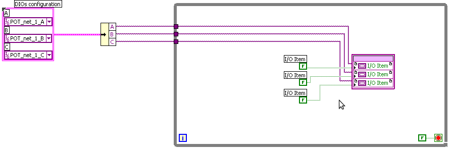
"" When I try to compile this code LabVIEW FPGA and LabVIEW crash each during "generating intermediate files.
He doesn't like these variables "FPGA I/o in" node of e/s FPGA.
"POT_net_1_x" constants are same standard DIOs.
Material: PXI-7841R
Hi CCM,
You may find that a simple reinstallation of the LabVIEW FPGA module will solve your problem.
If this isn't the case then reply here and we can try something else.
Kind regards
-
LabVIEW FPGA failure with compiler Xlinx?
I'm in LabVIEW FPGA 8.6 with NOR-RIO 3.0.1 (to 8.6). When I compile a simple program, I get the notorious:
«Error starting compile step: make sure that a compatible version of Xilinx tools is installed in the location specified in the setup of LabVIEW FPGA.»
I checked the FPGA compile server and I ran the utility fixTlink.VI with no improvement. This produces two identical PC, neither one having a FPGA installed card.
Any ideas?
After further analysis, the problem was to be in our facility in LabVIEW FPGA 8.6. Using the correct Installer of NEITHER solved the problem.
This thread is now resolved.
-
LabVIEW crashing whenever I try to execute / compile an FPGA VI
I have a project of RT using a cRIO-9012 / 9112 and every time that I hit on the FPGA VI, the compilation process starts but immediately blocked LabVIEW. The FPGA code is simple - just a development which is basically copied from the VI example OR for the module OR 9214 starting point. I have LabVIEW Real-time, LabVIEW FPGA, OR-RIO installed (LabVIEW 2013 32 bit running on 64-bit Windows 7 computer), Xilinx tools 14.4 installed. The crash error report dialog box is shown below:
I don't know what it takes then try to diagnose and correct the problem. Thoughts?
If it turns out that I had explicitly wired constant I/O device to the i/o method node FPGA and FPGA to IO property under my VI, who, for some reason, was originally the compiler crashes labview. Remove these constants and in defining the elements of e/s instead in the context menus in right-click for both types of nodes seem to have eliminated the fracas.
-
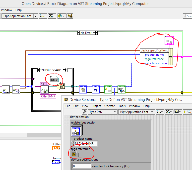
I play with a VST 5644 and model VST streaming. On the FPGA VI, I added the code, then added an indicator of the face before of the FPGA VI and compiled. Executes the FPGA VI in interactive execution mode, the indicator works well. Side host, however, I can't access the new indicator with read/write control.
Coming out of the open FPGA VI reference I can see the indicator on the wire, but in the Dynamic Cast of Interface FPGA function is have rooted out the refnum somehow. If I connect to control read/write directly to the output of the function of open reference I can access the indicator very well.
No idea what I am doing wrong?
Thank you.
You re-configured your FPGA VI reference with the new bitfile interface? The cast of dynamic interface defines the lead as all methods and indicators according to the type of wire connected. You can right click on the constant of type and select "Configure the FPGA VI... of reference". In the pop up window that follows, select "import of bitfile...". "and select the new bitfile you've built.
You must update the fpga reference type in the "Device Session.ctl" type def as well. This is the type that you will be able to access throughout the project.
-
FPGA code with the evolution of the modules
I need to create FPGA code to a cRIO-9072 facing the development of the modules.
My cRIO will have a number any NI 9203 (analog acquisition) and modules OR 9411 (acquisition digital) as inserted by the operator. When turning the power on, the system must identify two possible modules were inserted in each of the slots. Subsequently, he will then know what choices of code to call to acquire data from the individual modules.
I found the article in the knowledge base for CRY that queries each module and again reports the type of module and I can use it to successfully detect modules, but what LabVIEW fails to allow me to do this is to compile my FPGA code that was designed to deal with possible modules. After compiling, I get the error: "IO found point FPGA project. You must add the I/O item in the Project Explorer window, or select a different element in the control of FPGA of IO or the constant"because the compiler requires the appropriate modules are configured in the LabVIEW project. Unfortunately, this would require two different modules to be configured for each slot at the same time as there are sections of code for the 9203 modules and sections for 9411 modules for all eight locations coexist in a vi.
Anyone have any ideas on how to get LabVIEW to compile my FPGA code somehow?
Many thanks in advance,
With the current draft of LabVIEW FPGA, you cannot compile a LabVIEW FPGA VI which manages several configurations of C Series modules.
For your application, you must create a target of your project for each of the possible configurations of module and build the corresponding FPGA VI. Then, compile each of the screws to create the necessary for each configuration FPGA bitstream. Then in your host VI, you can detect what the current configuration of the module and download the binary stream appropriate for the FPGA. Another issue to consider is that the reference to the FPGA VI/bitstream returned by the open FPGA VI reference function will be unique to each bitstream/module configuration. So in your host VI, you'll need treat each configuration of the module with a separate set of code by contacting the FPGA.
If you consider only two different modules and an eight slot chassis, there are 9 modules possible combinations. The condition would be to the end user to place all modules of the same type together, either from the left or the right side of the chassis.
-
FPGA: update w / 14,4, fails w / Vivado 2013.4
My FPGA code that compiled fine in LV 2011, then 2013 LV (using Xilinx 14.4). I didn't contact for some time...
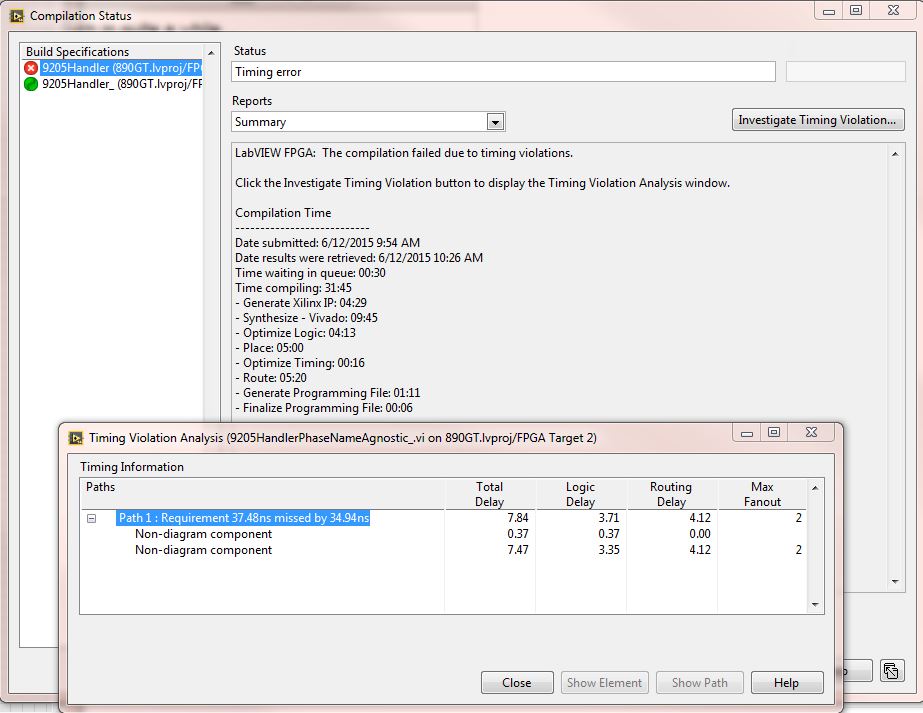
The upgrade to SP1 2014 LV, I believe that I have to re - compile to get the bit file to run on the target of the cRIO. However, now it does not compile. Cloud compiler error of timing. Clouds (local and compiler and elsewhere) report using Vivado 2013.4
The code handles a moudle of analog input of series C 9205. 6 of the 32 channels are run by a calculation of RMS. A time loop is set to do this each 185 uSec (9205 card channels = minimum update 4uSec * 32 channels = 128uS = maximum theoretical to run the FPGA and to obtain valid data). Each value of 650 samples a new RMS is calculated.
The rest of the channels get on average, 8 samples are averaged every 100th iteration of the loop above.
The timing of the loop is a front panel control. I tried this increasing by 185 to 200 uSec, but it does not help. All inputs and outputs to the FPGA VI are written in / reading of the *(cRIO-9068) of host real time be using the controls on the front panel.
This code has not changed in a very long time. I could share it if it helps.
My questions around the investigate Center window timing results. Here, nothing seems useful. What is "path 1' and how is it related to the block diagram? View items and path are inhibited. I have tried to change the build - optimize the performance and optimize for area etc... but the compilation always fails.
I will create a ticket with NEITHER. But thought pehaps someone here might have additional guidance.
For applications using hybrid...
(1) update install to 14.5 CompactRIO: C Series Module Support 14.6
(2) change of generation to optimize performance
-
Compilation failed due to an error of Xilinx (410)
Hi guys,.
I am compiling my FPGA with the Service Cloud to compile code. I have a FPGA code that compiles without any problem. When I put a knot of FIFO of DMA in this code, I get the error on the Xilinx compiler at the following address:
ERROR: HDLCompiler:410 - "/ opt/apps/NIFPGA/jobs/CSD2awO_GQdD63p/NiFpgaAG_0000050c_CaseStructureFrame_0001.vhd" line 211: Expression has 66 items; 50 EXPECTED
Netlist NiFpgaAG_0000050c_CaseStructureFrame_0001 (vhdl_labview) remains a black box, due to errors in its contentThe code compiles fine without the node of DMA. The DMA is a target to host DMA, 1023 long element (block of memory), the type of the elements is U32.
There is something else on the block schema as well. When I copy the SCTL in a new VI without anything in it, it compiles without problems, without worrying if the node of DMA is here.
Please find the extract VI and the attached summary of errors.
All ideas are welcome.
See you soon,.
Norbert
If the problem seems to be resolved...
I deleted the DMA FIFO of the block diagram node and he still added. After about 40 minutes, I had a successful compilation. Weird.
-
FPGA - try to use the screw of the replication of RIO to replace going to reset the FPGA running
Running LabVIEW 12.1
We have an application that uses an FPGA that was compiled in Run to Reset (works on any reset or power on). Sometimes we need to update the image on the RT and FPGA and I downloaded the NI RIO replication screw.
The problem I have now is that when I got to download the bitfile on the Flash FPGA on the sbRIO9636, I get the following error:
Error-61141
Possible reasons:
LabVIEW FPGA: The operation could not be performed because the FPGA is busy. Stop all activity on the FPGA before asking this operation. If the target is in the Interface of Scan program mode, put in FPGA Interface programming mode.
My updater is stand alone EXE. He isn't able to get a link to the FPGA, because we are not sure what Bitfile currently is on a particular system. I tried using the open FPGA reference and load a VACUUM on the FPGA bitfile by setting the FPGA to RUN when he sound the FPGA VI of the Open reference - and it works for me to erase the bitfile. It does not allow me to immediately after run the bitfile VI of replication of RIO download - even if I close and reset the FPGA before trying to download the Bitfile for the RIO Flash.
I have to first delete the existing bitfile, then load a new?
Well, I found what I consider as a workaround - but maybe it's required to do things - but it doesn't seem like it should be, since the RIO device Setup.exe is able to flash or clear the bitfile regardless of the State of the FPGA.
What I've done is to define the FPGA to "do not load automatically on re" then call the RT Config screw system and order a restart of the system. The RT operating system restarts and then restarts the RIO system and this ensures that the FPGA is not busy. Then I'm able to erase them or write about a new bitfile for the RIO Flash and set the "Automatic loading on any Reset" Rio de JANEIRO and restart the system again.
Our current situation, it will work. Long time restarts do a bit of headache.
-
To access the symbols parolees disable FPGA of host machine
Hello
Is there a way to programmatically access the conditional FPGA disable the host machine symbols? I would like to have a host VI who could know if, for example, the bitfile FPGA has been compiled with ENABLE_AO or not.
solarsd wrote:
Thanks for the tip. I was about to resort to something like that, but I thought that it would be uneconomic in terms of FPGA resources, I didn't know that it was minimal. Furthermore, you happen to know more in detail how something as in the pobrepablo1 example (btw, thanks for the illustration) would be completed in the material? What is the cost of a Panel control before FPGA? I was getting the impression that this is important - in one case, I could only include the VI my FPGA by changing some controls in the constants.
You can get an idea of the use of the resources of statistical resources on the use of FPGAS screws. For example, I chose an FPGA random ones listed, and the table indicates that a Boolean or indicator control uses 3 flip-flops and 3 lookup tables, which is almost nothing. A constant uses resources from 0 (no logic). If your conditional constant disable can have more than 2 values, an 8-bit value is not much more expensive. If you have more than 256 possible values for a conditional disable, you're probably something wrong
 of course, I would not recommend using a string as in the example of pobrepablo, because it would be very expensive. That's as much detail as I can provide.
solarsd wrote:
I find such behavior of weird symbol be honest. I realize that these symbols are gone after compiling, but everything is managed in a LabView project, if the symbols must be available throughout. I think changing the symbol value will trigger a recompilation of bitfile FPGA anyway, so the 'source' and the binary files are synchronized. The FPGA "bitfile", as I see it, must have a code of host interacting with the driver card hardware FPGA, i.e. where the State of these symbols must be exposed to the user in my opinion. Just trying to understand the logic behind this.
You can configure LabVIEW to open a bitfile on FPGA directly, without the VI used to compile. In this situation the VI and bitfile are not synchronized, and the bitfile could have been gathered in a different project with a completely different set of symbols parolees disable. The only way to guarantee that the bitfile is compiled with the right settings is an indicator on the front panel. You can take a look at the bitfile, it is just XML, and it doesn't even include the version of LabVIEW, used for the compilation. You can use a bitfile to a version with one crowd on the other, as long as the bitfile format has not changed. Disable conditional symbols are removed before the VI (in the intermediate form) is given in the Xilinx tools that actually create the bitfile. NEITHER could add more information, such as the value of the disable conditional, to the bitfile XML symbols, but there should be enough demand for them to do and they would then also need to add a mechanism to access this information. I could be wrong, but I don't know that enough people would find useful to a value of this change, when it is so easy to add an element of façade. Still, you could post on the Exchange of ideas FPGA and see if there is interest.

Maybe you are looking for
-
When you connect to secure sites, there was a lock on the lower right part of the page that shows that the site is safe and secure. If the secure Web site wasn't sure a red line would cover the lock. I don't have it more since I've updated from 3.8 t
-
Hello I plan to do number of Skype for my startup company. Would it be possible to take in charge the number obtained through Skype where I have stop using it? Thank you very much
-
Can someone tell me what function the attached photo is? Could not find function in pallets - so thought that I could ask here.
-
Windows XP does not start because < root Windows > \system32\hal.dll file is corrupted
I get the following error message when starting my windows XP Home PC. : Windows didn't start because the following file is missing or damaged \System32\hal.dll. Please reinstall a copy of the file. How do I do that?
-
bcmwltry.exe with / DLL initialization failed in windows xp
I write a question on behalf of the client. Here's the problem of the customer: Playing Cityville Facebook my laptop crashes every time with the following problem, bcmwltry.exe with / DLL initialization failed. I don't know what it is or how to fix i