Input voltage graph is not
I am connected to a NI9215 with a resistance of 1Mohm between my com and IA-. I recently got my fixed shift, but when I put a voltmeter Terminal screw, I read 1.0V and my chart reads 1.4. What Miss me?
Tags: NI Software
Similar Questions
-
digital input voltage measurement
Hello.
I develop software for a test bench.
(the material has been developed in the past by someone else, and I have to use this material now)
I have to read some digital data with one nor usb 6501.
I measured the voltage on pins levels and realized that to logic 1, I get about 4, 7V, logic 0 about 3, 5V (who, after having converted to digital, is always 1).
You have an idea how I could fix this?
I thought that if I could somehow put the analog value of voltage on the PIN, the problem would be solved, but I n ' not know if it is possible.
Thanks in advance.
Katona
Hello
the 6501 low input voltage (false logic) is 0.8V and high voltag of entry is on the order of 2.0 v to 5.8V. You must use an electrical circuit or device with an analog entry order to solve this problem.
What do you think of "Schmitt Trigger"
http://en.Wikipedia.org/wiki/Schmitt_trigger
Concerning
Rüdiger
-
Multiple waveform graphs do not simultaneously view data
Hello
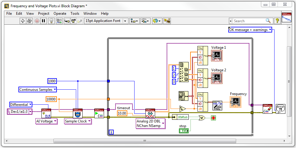
I use a box USB-6009 to acquire three analog input voltage signals simultaneously. I want two plot the voltage wrt time signals, while the third signal, I want to extract the frequency and then draw the wrt time frequency. I want the three of us graphic waveform having a category axis in units of seconds from zero seconds. My diagram of block VI is below:
When I run the VI, I get some problems. First, the frequency table is not plotted all the data, and although I am happy, time begins and reset it's count in tenths of seconds rather than in seconds.
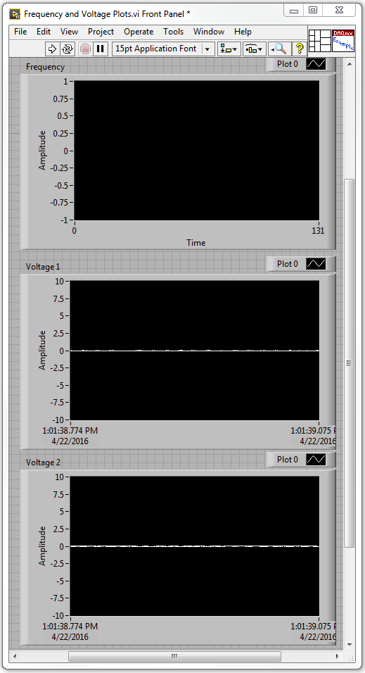
With the voltage 1 and 2 maps, the voltage is read correctly, but the x axis are in terms of date and instead of seconds. The front of the VI is below:
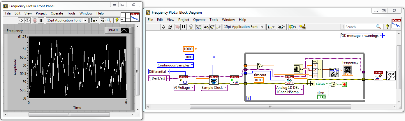
I tried to run the VI with only the third signal voltage being played and the table of wave shape of the plots the frequency perfectly. The Panel diagram and the block before lower is to:
Could someone tell what I'm doing wrong in the first VI?
1. you must use the version of waveform table Mutiple multi-channel DAQmx Read Points. Then, you don't have to accumulate the waveforms yourself.
2 tables index is 0-based. Thus, the filrst of the table element is actually 0, not 1.
-
Analog input voltage assistant DAQ
Does anyone know why theres error when you use two assistant DAQ (in a while loop at the same time) for reading of the analog input voltage?
There is not a problem if you use a wizard to data acquisition for analog input voltage reading simple.
If you get an error, wouldn't it useful that you have told us what it was, we may be able to explain it?
I'm guessing that you have error-50103, and if you look in the forums for '50103' (leave out the negative sign), it will give you the answer for this question has only requested thousands of times before.
-
I use a cRIO 9004. I noticed it has a chassis temp option. I was wondering if there was a way to find the input voltage. My unit is battery powered and I knew my batery voltage level. I'm doing some kind of a voltage drop detector.
I am a novice to Labview - I'm sorry if I missed something obvious.
Thank you.
You have not forgotten anything. Currently, there are no i/o chassis set up to read the voltage on your power supply. You'd have to do is to use an analog input module to read the voltage yourself.
Kind regards
-
Using the DAQ USB-6009 meter and an analog input voltage at the same time.
Hello
Currently, I'm reading the two channels of voltage with the USB-6009. It happens that one of the channels is the output of a digital coder, and it would be much easier to use it directly to the PFIO entry that is defined as a counter. The problem I am facing right now, it's that I can't use the DAQ Assistant to use the analog voltage to a channel and the digital channel counter at the same time. Once I put the DAQ Assistant to read the input from analogue voltage, I won't be able to add analog inputs. And as I put the DAQ Assistant to use the PFIO as a counter, I can add more entries to read analog voltage is.
I wonder if it is possible to solve this problem using the lower level data blocks? Another solution would be to read two channels in analog input voltage and that the use of Matlab to process data resulting from it, since I was not able to do the counting to work simultaneously with the acquisition in Labview to impulses.
Hope you guys can help out me.
Thanks in advance.
Using a simple wizard of DAQ is incorrect. You need one to acquire analog inputs and one for the meter.
-
Configure the input voltage range
I use an NI USB-6221 with SignalExpress 3.0 card.
The Spec for the 6221 map specifies 4 analog input ranges of +/-10V, 5, 1, & 0.2.
My question, how is the range of input voltage on the map on one of the beaches specified?
The closest thing I can find in SignalExpress is step 'DAQmx aquire', looking at the tab "configuration" of "Configuring the stage." There is a group called 'settings', there are areas of maximum and minimum input Signal, but context-sensitive help indicates that it is expected for the channel after the scaling values.
I also looked into MAX, but I see no way for me to directly configure one of these ranges.
Can someone explain how this works?
Mike
You look at the right thing. When you specify the min and max, the DAQmx driver and then automatically selects the best range of this signal. For example, the Council supports + /. 1 + /-1, at ± 5 and ± varies from 10 volts and a jury of 12 bits. If you enter max/min to + /-2, the jury will be set to the +/-5 volt range. Your resolution is then 10 (oscillation of the total voltage) volts divided by 4096 (2 * 12).
If you were using LabVIEW, you can get the actual voltage selected range by using channel properties DAQmx AI. Rng.High and I. Rng.Low. If you specify a min and max that is less than the amplitude of the real signal is greater than the actual scale used, then you cut your input signal. DAQmx does not have an autoscale. Take a look at Page 4-2 in the Manual of the M series.
-
Tab 2 of the A10 input voltage?
I wonder if tab 2 a10 should work abroad where the electricity voltage is 220 instead of 110.
Any help would be appreciated. Thank you!
You will be fine, that the C - P35 AC adapter is bitensión with 100-240V input voltage range
Output 5.2V 2A.
-
Q150 input voltage? Help, please
I sent twice, named Sales and no one yet knows the Q150 input voltage...
Can someone view detailed list of specifications of Q150 which includes its input voltage? Or anyone who owns a Q150 can look for me?
Thank you
Hi ciguli and welcome to the Lenovo user community!
Said manual material: 100-240v AC:
http://consumersupport.Lenovo.com/us/en/Userguide/Guide_list.aspx?CategoryID=741912
-
I have a problem with the graph xy is not showing do not. Tried almost everything I know. The graph will not just show the two tables. I tried to build an array of clusters in the chart, and that did not work. attached, that's what I'm trying to do. Something simple for my class involving the equation of motion and the mathscript. Any help would be greatly appreciated.
where set y0?
-
I need a file to an exact width and height and it must be in png format, because it allows to translucency. My graphics are only the top of the page and when I export only the graph is not exported the entire file. How can I get the entire file of export including blank parts?
in the export dialog box, you have chcked 'use of work plans? ''
-
Area of the graph under the graph and not next to the chart legend
Hello
I need to display 1. Graph legend below the graph and not next to the chart area and also reduce the space between the caption box
2. the values in the chart are affiches.1745%, 4.596%... I need to round up these values.
My card code is:
chart:
< graph graphType = 'PIE' depthAngle = '50' depthRadius = '8' pieDepth = "30" pieTilt = "20" seriesEffect = "SE_AUTO_GRADIENT" >
< title text = "Answer category" visible = "true" horizontalAlignment = "CENTER" / >
(< LocalGridData colCount = rowCount="{count(.//G_DT_NON_NA_EQUITY1) '1'}" > "
< RowLabels >
< xsl: xmlns: xsl foreach = "http://www.w3.org/1999/XSL/Transform" select=".//G_DT_NON_NA_EQUITY1" >
< label >
< xsl: value-of select = "SPER_STATUS_TXT10" / >
< / label >
< / xsl: foreach >
< / RowLabels >
< DataValues >
< xsl: xmlns: xsl foreach = "http://www.w3.org/1999/XSL/Transform" select=".//G_DT_NON_NA_EQUITY1" >
< RowData >
< cell >
< xsl: value-of select = "CNT20" / >
< / cell >
< / RowData >
< / xsl: foreach >
< / DataValues >
< / LocalGridData >
< / chart >
I appreciate all the help
best regards and many thanks
Bhavana -
Excel input parameter graphs not valid?
Hello
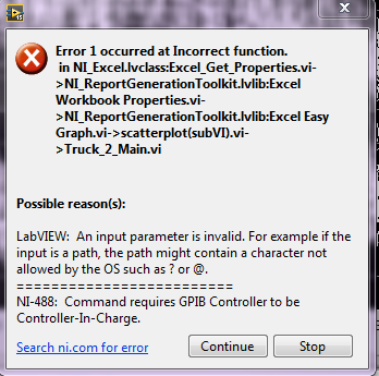
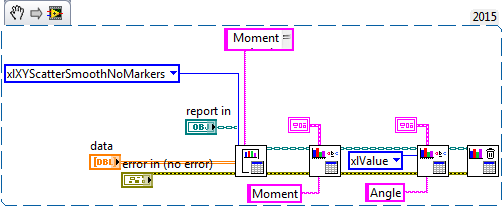
I'm not very familiar with the intricacies of the report generation using specific Excel screw, so maybe I'm missing a blatant mistake here, but I have three separate graphs that I would add to a single excel file, each on a separate sheet. I can generate the data and record a single chart very well, but for some reason when I have three going at the same time, an error pops up like this (three times)
I used the run culminating to find when the program stops and it seems to be the first great VI in my Subvi scatterplot, but I do not understand why the input parameter can be invalid when he works with a single chart.
Looks like my Subvi the cloud of points, and I also included a zip file of my project as a whole.
Thanks in advance for any help!
Hello
I think that the error may be due to the same reference report being used and closed several times. The cloud of points Subvi closed the same reference three times and as a result the main VI. Try to have the subVIs run one after another and close the reference at the end.
-
Inputs voltage DAQ affecting each other and the camera, they save you of
Hello world!
I use ELVIS II + and LabVIEW 2012 to register a device with a resistive sensor voltage (voltage see with ELVIS II.jpg for VI). The device (device + ELVIS II Schematic.jpg) measure the voltage across the resistive sensor and is controlled by a msp430. If the msp430 believes the change of voltage of the probe is above the threshold, a light is on. There is a motor function on the device and the LED is normally not on when the engine is turned on. I found that registration with the acquisition of data affects the behavior of the device. The reasons daq hardware and devices are connected. During data acquisition does NOT record, gross and analog sensor in tensions are constant (and the LED off) while the engine is on (Figures.doc; (A). when data acquisition IS recording, the engine power seems to distort analog in / raw voltage of the sensor causing the LED lights up (Figures.doc; (B).
The trials that did not issue (led on while engine):
1. registering with new ELVIS II + DAQ
2 separate inputs raw and engine sensor on data acquisition
The tests which fixed the problem (any engine LED is off):
1 grounding gross and/or motor sensor
2 separate channels of raw and engine sensor in the wizard DAQ (Figures.doc; C: shows engine and raw sensor separated by A_VCC. Figures.doc; D: where engine and gross sensor are side by side). I don't know why the order of the channels in the DAQ assistant would affect the behavior of the sensor signal.
Any advice on this problem and ways to troubleshoot/potential long-term solutions would be greatly appreciated!
Thank you!
If your device has no acquisition of simulteanous, then each channel is multiplexed in the ADC. It has a capacity of entry inside your device, which gives it a 'memory '. If the voltage stored in the capacitor is not unloaded a scan before the next scan starts, then the second scan will "remember" is the result of the first analysis, give you really weird problems. More source impedance on the canal e e greater probability that the signal from the previous 'remembered '. That's why the order of the questions, the higher source impedance going first.
-
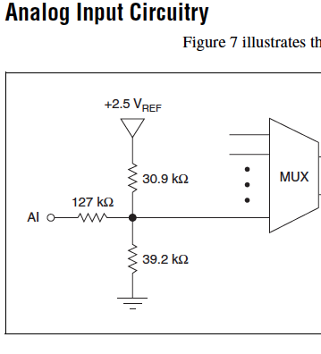
Cut-off for the 6008 analog input voltage
I am using the analog inputs NI USB-6008. The specification says they have a 144 k ohms input impedance. But it does not say what is the cut-off voltage. If you leave a disconnected and measure the voltage you will get 1.4 volts. So I guess it's the cut-off voltage, but it is not spec'd.
Someone agree that these Amnesty International isn't terminatied by 144 k - ohms to 1.4V? Is this in the documentation somewhere?
Figure 7 on page 16 of the NI USB-6008/6009 User Guide and specifications shows the strange input of this unit circuit.
Lynn
Maybe you are looking for
-
Then...
-
Toshiba 40TL938G blue screen on the initial screen - invalid service page
Hi guys,. Today my Toshiba 40TL938G give me a bad joke.When I turn on the TV it gives me a message on blue screen (like windows) tells me"frequency of update and you have to search again for channel" and later "is not a valid service. I can't do noth
-
Hello, my question is about the upgrade to Yosemite to El Capitan. I converted to Windows, and I would like to know if theres a way to clean install El Capitan without having to download the installer from the App Store. He just write about Yosemite
-
as the title says... Please help... I don't like this update...
-
overlap of XY graph with xscale property
Hello I have a problem using the xscale maximum and minimum property... when I use the nodes property that it straddles two sets of curves in the same graph: one with the scale I put and the other as if I haven´t the value of the xscale assets... Wha