LabVIEW Maximum controller handles
I'm looking at the use of labview to sample variables 10-15 to 10-15 different Galil based controllers (DMC22xx, DMC40x0, and some RIO 47xxx) Ethernet. I was wondering what would be the maximum number of concurrent connections on an Ethernet network?
I would like to be able to record and display these values about a rate of a set of samples per machine per second.
The limitation must be based on the number of available ports and addresses on the Transport layer. This is a limitation of TCP (65535).
Tags: NI Software
Similar Questions
-
Freescale in the LabVIEW ARM controller?
Hi all
Is it possible to use the freescale MC9S12XEP100RMV controller in the ARMS of LabVIEW?
Thanks and greetings
Ben aljia P
Hi Suren,
The LabVIEW Embedded Module for ARM Microcontrollers using the "Keil uVision development toolchain to compile, download and debug applications", as this article explains. (Taken peripheral ARM supported by LabVIEW)
With this in mind, you should be able to use any microcontroller that supports the "RL-ARM real-time library." Keil device database lists microcontrollers currently supported with this library. (RL-ARM real-time library)
The Freescale MC9S12XEP100RMV MCU is not listed as being supported. Knowing this, you will not be able to use the LabVIEW Embedded Module for ARM, but you can use the LabVIEW Microprocessor SDK of Module. The only difference is that the ARM Module has been built on the Module SDK. The Module SDK is more "generic" and allows to develop support for virtually any 32-bit microcontroller software.
I hope this helps.
Kevin S.
Technical sales engineer
National Instruments
-
What is the best way to open close, then send instrument labview teststand model handles parallel?
I have a number of test systems that use a parallel model with labview. We have a number of instruments (PXI).
What is the preferred method to open, close and passing instrument handles with labview teststand?
Hello
A few ways
1 package return the session as a U32 handle, there are a few VI TestStand i of the palette of TestStand that you can use to make conversation.
2 through a LabVIEWIOControl. TestStand handles these.
3 do something fance as the use of LVGOOP and leave the handle as an object property and leave in memory. for example, do not pass it back at all.
One thing, you'll have to monitor multiple executions trying to talk to the same instrument, use some lock/unlock or synchronization to avoid thi.
Concerning
Ray Farmer
-
Hello
I try to connect LabVIEW to controller using an OPC server of NOR. Its a controller logix (Allen Bradley) L23E Compact and I find it difficult to obtain the device driver. Please help me with this topic and a link explaining how it would be useful to connect labVIEW to PLC.
Thanks in advance,
Sunil
Hi Sunil,
Regarding the driver: See the taken list supported device & driver plug-in for NOR-OPC Server
Regard to the connection in LabVIEW: You have two main options that depend on the question of whether or not you have the LabVIEW DSC Module. As seen here, you can either use variables shared with DSC to access your OPC tags, or you can simply use DataSocket VIs contact them directly as an OPC client. Some documents that may be useful by adding your specific hardware can be found here and here.
I hope this helps!
-Greg J
-
After installing 2011 LaBVIEW and NI-VISA 5.1.2 on CentOS 6.2 PC, I noticed a problem trying to use the LabVIEW vi VISA, basically it does not work for me, LabVIEW crashed when trying to create a control, or a constant for the open VISA vi. Tried to launch VISA tools, they all start and then close abruptly. Trace IO OR only shows a single line.
I read however number of threads and decided to collect the system.log NOR, which is attached. (system.log.gz). I noticed a strange message here on nivisaserver:
/ usr/bin/tail - lines = 25 var:
22 May 11:18:48 abrtd localhost: 'nivisaserver' Package is not signed with the appropriate key
22 May 11:18:48 abrtd localhost: corrupt or bad dump /var/spool/abrt/ccpp-2012-05-22-11:18:48-3258 (Re: 2), deleting
Thank you!
MountainMan12 wrote:
After installing 2011 LaBVIEW and NI-VISA 5.1.2 on CentOS 6.2 PC, I noticed a problem trying to use the LabVIEW vi VISA, basically it does not work for me, LabVIEW crashed when trying to create a control, or a constant for the open VISA vi. Tried to launch VISA tools, they all start and then close abruptly. Trace IO OR only shows a single line.
I read however number of threads and decided to collect the system.log NOR, which is attached. (system.log.gz). I noticed a strange message here on nivisaserver:
/ usr/bin/tail - lines = 25 var:
22 May 11:18:48 abrtd localhost: 'nivisaserver' Package is not signed with the appropriate key
22 May 11:18:48 abrtd localhost: corrupt or bad dump /var/spool/abrt/ccpp-2012-05-22-11:18:48-3258 (Re: 2), deleting
Salvation mountain,
Thanks to attach the report system log - I think I have a solution for you :-) Let's look at some of the lines:
890: / proc/meminfo:
891: MemTotal: kB 38947121726: / proc/iomem:
...
1784: 100000000-12dffffff: System RAM
1807: / bin/dmesg:
...
1820: RAM BIOS fitness card: 2576: [nipple] more than 4 GB of memory addressable detected.
...
1838: BIOS-e820: 0000000100000000 - 000000012e000000 (usable)
...
2576: [nipple] more than 4 GB of memory addressable detected.
2577: [nipple] this configuration is not supported. Check the release notes for more information.Starting at the bottom to 2576.2577, dmesg lines had more than just the NI-VISA signature notification server. To start the system, the kernel modules OR refused to load because they detected more than 4 GB of memory addressable. But, if you look upward to the 890.891 lines, meminfo says that you have less than 4 GB of memory system, which makes it appear as modules OR don't know what they are talking about. However, if you look at the report of iomem down on lines 1726.1784, system RAM was relocated above the 4 GB limit. While your system has no more than 4 GB of RAM, part of his memory addresses beyond 4 GB, which can not use modules OR and so they refuse to load. -What happened? Your BIOS has provided a physical map of the RAM with usable over the threshold (line 1838) addresses.
The difficulty here is simple: you must specify the kernel to reserve addresses beyond 4 GB [1] so that it won't remap RAM into a memory. Once all the RAM addresses below 4 GB, the modules must load and VISA/LabVIEW/al. should stop bad conduct.
It seems to me that LabVIEW does not handle this situation very gracefully, and maybe you can work with Kira to file a bug report.
[1] re: success SUSE linux and DAQmx installation; nilsdev and other missing utilities.
-
Manual of PID for transfer Auto smooth
Hello
I am using the PID command for a pump to ISCO syringe with manual Steplessly in automatic control, but I can't seem to make it work.
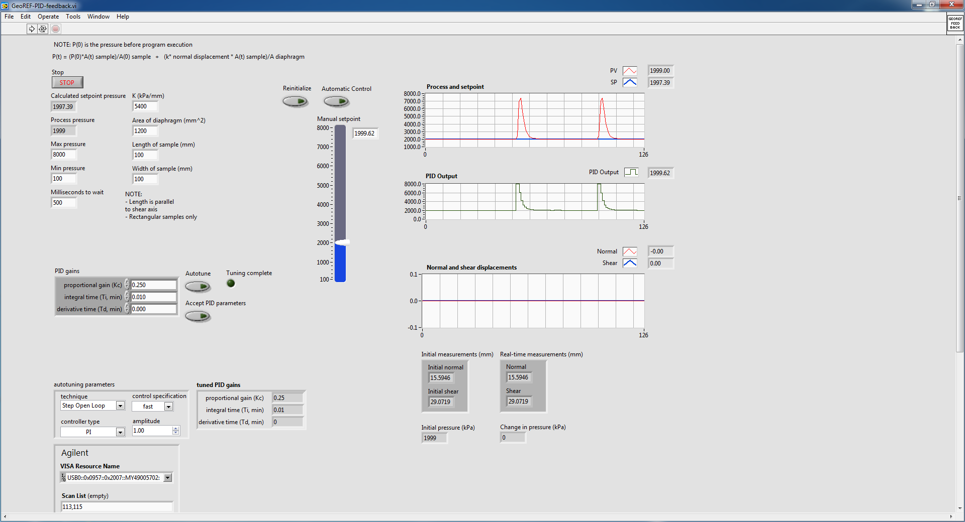
This shoot-syringe has an entry and exit pressure and is used to apply a force to keep the vertical movement of a constant of the sample. The amount of applied pressure is related to vertical displacement by an equation that appears in the attached VI. This VI aims to apply a variable force according to the displacement of the sample in order to try to keep moving 0.
Here is some general information on the pump that I use:
The pump is autonomous and can independently maintain pressure regardless of the LabVIEW PID controller. The pump only takes pressure of LabVIEW controls and maintain this pressure until another pressure control (I think that the pump integrated into the controller itself is a regulator PID.)
The problem I have is if I start the VI with the pump at a constant pressure (using the hand control with advanced PID VI) and crossing the wire to automatic control, the advanced PID VI immediately shows the pump to adjust the pressure up and then slowly bring it down to the steady state. This happens even if the hand control pressure is stable and identical to the auto set pressure. This following image details what I'm talking about:
The pump is in steady state, as shown in the diagram of pressure and the value in manual initially and then toggled mode on automatic control (designating the huge bump). I did it twice to show what happens when I go back. Manual automatic is without suddenly, because I used a local variable to constantly change the manual set temperature.
I did some troubleshooting and experiment and here are some of the results that I found:
1. when going from manual to automatic control, PID regulator sets the maximum pressure and then slowly bring it down to the set value
2 when it is cold from the VI in automatic mode with true to reset, the PID controller sets the pressure at a minimum and then slowly bring it up to the set value. This occurs even if the value of the original process is close to the set point (feed the actual value in the PID controller before execution also does not help.)
I also tried to play with the gains of PID in VI and found that if I turn off the 'I' and parameters "D" (together the two to 0), I no longer suffer from the huge bump, but the PID controller can bring the real set point value as there is always a lag.
I don't know if this is a result of bad PID tuning, but after the initial bump in the transition between manual and automatic, the PID controller seems to be able to maintain the correct pressure well.
The reason why I am using a PID controller rather send the pump controls (since it can independently maintain pressure) is because it is much smoother.
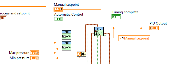
In the attached VI, there are a few side screws that are called that are specific to the pump and the LVDT used for detection of vertical movement. I do not think that they have an effect on why I don't get a transfer smoothly without jerking, so I only put comments to explain what they are doing.
I found another thread in forum with a similar question, but none of the solutions posted it seemed to have helped me. Here is the link to this thread:
http://forums.NI.com/T5/LabVIEW/PID-manual-to-auto-bumpless-transfer/m-p/3180609#M920098
Thank you.
Best regards
Victor
Your topology is not quite how we recommend that you make the transfer smooth. Can you do something like this?
Who will do manual setpoint pressure (units) and you need to update your gain, but it should follow. What is an option?
-
NEITHER LS CAN map with SJA1000
Hello
I use card PCMCIA 2 of the series low speed CAN with SJA1000 transceiver to communicate with a SHIELD with a transceiver MCP2551.
But when I try to communicate with the ECU using CAN Api in LabVIEW it says there is error of the transceiver.
What could be the problem... ??
I'm cluleess...
I use NI CAN 2.5.2 and LabVIEW 8.5
I checked the ECU sends messages CAN, but I'm unable to read through LabVIEW.
Help!...
Smitha,
First of all, we need to straighten a terminology: the SJA1000 is the CAN, not the transceiver controller. The Low Speed CAN Interface uses a transceiver TJA1054A. The controller handles the transmission and receipt of messages; the transceiver works at the bit level, moving the digital signal levels from the SJA1000 for the levelsfound of more high voltage on the CAN bus, among other things. A quick search on Google reveals that your transceiver MCP2551 is actually a high-speed CAN transceiver, not a CAN transceiver low speed.
The low speed of CAN will interface does not work with this SHIELD because it uses different termination, where the trasnceiver error.
Fortunately, you can change the transceiver on the PCMCIA-CAN interface. The transceiver is the small black box at the end of the dongle, and you can change these dongles for the correct high-speed CAN interface. You can get these dongles here. You will need the HS/HS variety (or a HS/LS if other devices low speed to use on the other port).
http://sine.NI.com/NIPs/CDs/view/p/lang/en/NID/1330
More information about networks broadband vs CAN low-speed here:
http://digital.NI.com/public.nsf/allkb/84210794086E9C0886256C1C006BE6AE
I hope this helps.
-
I am reading the temperature and to write a set from a Watlow 96 temperature controller value. I searched the forums and downloaded a driver called Watlow96.llb by Brian Vibert (around 2003). As far as I know, everything is set up correctly (corresponds to the speed of transmission between the computer COM port, etc..) However, I get a time-out error. I was not able to read or write anything to the controller up to now.
At this point, I use the trial version. The extent of the material, the Setup will, I tried to use the driver on a computer with a built-in COM port. I also tried to use a USB Belkin F5U409 serial adapter.
I'm new to all this, but I tried to do my homework. Here are my thoughts, and I will describe where I am stuck on each of them. Any help would be appreciated.
(1) I don't know if I'm communicates with the device through the COM port. All the possible indications are that I should be using hyperterminal, but I don't know anything about it and I want to get feedback before as I have dive into another new topic. How to test if the device is properly communicate?
(2) can I use the DAQ assistant to start from scratch rather than use this driver? This device is not explicitly supported and has no affiliation with National Instruments. However, some legacy software in my lab with the help of LabView 7 apparently could read/write to the controller using the DAQ assistant (even though I'm still controls on it and waiting on the huge download DAQmx software package).
(3) the driver has a procedure quite complicated, buried in the code to communicate according to the RS232 standards. I only have an idea what this means, because I am a chemist by training engineer and this is all foreign to me. I presume that there are built-in LabView protocols to handle this standard, but I can't go looking for them in the right places. This is the case, and where should I look?
Again, any help would be appreciated. I'm basically give myself a crash course in LabView that I urgently need to know if I can tie-in, temperature control and certain measures of the instrument. The temperature control should be the easiest part, then I start here.
Thank you for any consideration.
Kind regards
Scott
The fix for this was simple enough, because it ended up being a problem with my computer recognizing the COM port correctly. After the reboot, the drop down menu to the COM ports was refreshing (while it was not before) and the program ran end out of the box.
-
reading of the analog inputs with RPC
Hello
Because LabVIEW can not handle this (in VI; the value that you have saved the excel file has not been the same, that I saw during the measurement...) This confused me for a long time
 ), I want to write a C++ program (IDE: Dev - C++) which can read & record 2 analog inputs of the NI USB-6009 box. For this, I looked for an example of National Instruments and I found a little. But my problem is that I can't even use any example, because it has always held a mistake, after that I have compiled and started.
The error once the task has been created and has the :-200220 error number with the description "device identifier is invalid. But I do think that its invalid, because it's the xP example
I must say that I am new in programming C++, which means I could have a rookie mistake. And I couldn't find documentation or something for the NOR-DAQmx library.
Someone has similar problems with DAQmx and C++ and know how to fix? I don't really know what I can do now without a working example or documentations...
Hi Mario
It's the same thing. You didn't just save all of the data:
Please take a look at my comments in the attached VI.
Christian
-
writing multiple modbus registers
Hello
I am communicating to my labview program controller using modbus RTU and the controller has 16 bits in modbus registers.
To send the float as '1.23' values, I write two registers to store the hex value that number in comma floating 32 bits.
I use the modbus driver provided to this end by labview and use labview 8.2.1
I have the following doubts in this regard.
- The "Modbus master series query. VI"has the command Modbus that records an entry which I use to set the registry values in the controller unit modbus. To send the above, mentioned in floating-point registers 501 and 502 (contains the full value of the PID parameters), use the same vi, whose value should be registered first... is the high or low, to be written to 501 and 502.
- The function code to write to multiple records in the modbus driver is 16. But my document that is specific to the Controller explained in the section "writing to multiple records" with the code of function like 10. And I see that feature codes 'writing in the single register' as well as the driver for modbus producing the same type of message frame as discussed in the document. But I see no similarity in the function "write multiple registers" in the document and the modbus labview driver.
- "Even if I write records 501 and 502 one after another will use"write in the single register"function code when these registries implement floating-point single using 2 registers ' 16 - bit '. If this method is possible, then I will come and do it the same way I did it for the entry in the single register. While writing data in records one after the other with a gap between the two as small as 4 ms scriptures do good?
I suspect a confusion between 16 decimal and hexadecimal 10

Two successive registry entries are not equivalent to a double entry: during the period between the two scripts your controller will be loaded with a false parameter. It is perhaps not necessarily a source of problems. It depends on your application. Writing the MSB should first reduce the problem.
The order of Hi-Lo is dependent on the machine control. Some use the Big Endian, other Little Endian. But this choice should assign unique register values (U16) as well.
If it is not documented, you should read the records and see if the result is logical. If this is not the case, invert the byte order and verify that the problem is resolved. Good luck

Also, I assume that you know how to use the conversion feature to convert a single (32-bit float) 2 U16?
-
How to load a pointer data memory in table
I'm trying to interface to a DLL used to manage a piece of hardware. The DLL is written in c. uses _stdcall and the Import Wizard has hooked up with success of most screws in a library; many of them work everything just as it is. I have also played with the knot of library function call and think that most of the time, I got the hang of it. I ran successfully for the odd Windows API call (e.g., MessageBox). However, I am a newcomer in Labview. My problem is related to a DLL function that requires a pointer to a block of memory, in which he then dealt with the material (in the form of table of UINTs) data. I want to display these data in Labview, through a table I guess. I think I found everything I need to do in terms of creating a table and hanging until the node of library function call with an input pointer.
I hope this would work IF the block of memory has been fully completed until the function has returned. HOWEVER, this is not how the DLL function. It creates a thread that exert to put data in the memory block after the function in the DLL. Extra features are available for face to discover if the data transfer is complete. I guess this is enough to refute the marshaling of data in Labview, unless there is some special commands for this purpose.
I thought maybe I should allocate the memory using the Windows API (LocalAlloc LPTR flagged so I get a pointer) and I wrote a little VI that allocates and releases the memory that seems to work. This way I can release memory when the transfer is complete. MY PROBLEM is, given the pointer to the block of memory, as returned by LocallAlloc, how can I get Labview to read the memory in an array of integers.
I am now a little stuck and would like to receive advice on one, how to convert the block of memory, or on a way to approach things btter.
TIA
SteveJM wrote:
So I have a working solution, which is basically the same idea as your suggestion, but uses the Windows API. I took the trouble to mention it, but when I looked more closely at 'MoveBlock', 'DSNewPtrt' etc, I realized that they are a static C library. This means that using them requires that you have a C development system and knowledge how to build DLLs on that. As it happens that causes me a problem, but it seemed like a hammer in this case because the routines you need are already in the kernel32.dll module. [Yes that makes specific Windows, but then you would need rebuild your dll for each operating system in any case].
This paragraph is completely inaccurate. These functions are integrated into the runtime LabVIEW, without which your LabVIEW code will not work. You have the guarantee that if you can run your LabVIEW code, or in the development environment or as a compiled application, these functions are available. No need for a C development system (if that were the case, don't you think someone would have mentioned in one of the many messages on this forum on the use of MoveBlock?).
SteveJM wrote:
It is true that you need to find a way to pass the pointer to the destination of reference. In other words, using a "handful" I guess. One of the difficulties is that the documentation for Labview is rather imprecise on what happening coming in and out of the function call. Unfortunately, the meaning of "Handle" is very dependent on context, so documentation should be much more detailed. If you select 'Manage' rather than "Pointer table" minimum size box disappears implying that Labview will take a pointer to a pointer to a format of Labview. It would then allow the size information in the allocation of the table and set the offset pointer approprately when passing a pointer to the function that would fill the memory. If the size of the table was large enough, it might be useful to tweak with this to avoid the copy useless (and allocation), but I don't have time now, unless I find the best literature which explicitly explains this gathering takes place for each option in the dialog box.
All the help you need is available. Set up a call library function node to pass by handle, close the configuration dialog box, right-click on the function call library node and choose Create .c file... You will get a draft of C with all structs defined for you, and you will see that the handful of LabVIEW table includes size information. There is no "triage." He is just passing pointers autour (and a few and Word-permutation of bytes due to problems of "endianness"). When you pass an array of pointer to array value, you get what you expect - LabVIEW dereferences the handle once and passes the pointer of table. It's exactly like a C function call. Nothing unusual occurs when the call is returned (with the exception, even once, "endianness" switch if necessary). That said, it's a bad idea to do what you want to do with a handle, because LabVIEW is allowed to move the table when he likes and has no way to know that some other functions still has this memory block to stay where he is.
-
Storage of samples of several analog channels (life-long)
I use a USB6356 to read 5 analog channels (more digital input port A)) simultaneously until you press a stop button. The idea is to represent all the signals captured on a temporal scale after the acquisition.
I am convert and storage of the 2D array that is captured in each iteration of the loop in another 2D array in order to have an output of 5 table lines (one for each input signal).
However, Labview can not handle so much treatment in so short a time table (I think that the main bottleneck is the 2D Transpose VI table) and accidents very soon (I have to kill the entire process and restart Labview). Is there a better way to do this?
See you soon
Your problem is that you have horrible memory management here. Whenever you add in the table, more memory is allocated, then the table is copied. You are basically out of memory.
1. use samples of N, N channels, 1 table D of waveforms for your Read DAQmx
2. change your chart to a chart and move it to be inside the loop. Maintain chart, a story, so you can still see the X last samples on it (1024 by default).
3. save your data in a file. I recommend using the DAQmx configure connection before starting the task. This allows the stream directly to a TDMS file for further processing.
-
Get the minimum frequency of three signals FFT
Hello
I put in work of a closed online using LABVIEW loop controller. There are three entrances of signal, the FFT of each signal must be calculated online and frequency spectra is the lowest to be detected.
The plot of the Spectra is attached...
Please advice on how to achieve...
Thank you
ruser.
-
Flashdrive USB 3.0 write protection error?
Good, then, one a few months ago I bought a new flash drive, a flashdrive Lexar 3.0 with 32 GBs. yesterday, I was copying a file to my flash drive, then he stopped at halfway with an error message. The error message:
I started to get a little scared, so, as usual, I looked online for help. Apparently, other people have had the same problem. I tried all methods I thought to use the command prompt to change the Windows registry. Yet, none of them worked again! My last choice was to format the flash drive. Then, I started trying to format it. Then, a familiar message box popped up: "the disk is write protected". (As seen above). I was confused; Why my flashdrive write protected? I looked everywhere for some kind of help. I couldn't find anything.
Other notes:
-L' error does not come from my PC. I tried to use my sister's cell phone to get in shape, and he gave me the same error message.
-My flash drive is not a write protection option. (It could, but I could not be aware of it).
-J' tried various other programs to try to format.
-There is no virus on my PC or a flash drive.
-There are about 20 GB on the flash drive, so it is not complete.-J' already tried using the registry.I hope someone can help me, because I really don't want not to waste my money on another flash drive that will just give me the same error.
Thank you once again!
What follows is the best source of info that I found for USB thumbdrive problems:
<>http://www.Uwe-Sieber.de/usbtrouble_e.html >
USB stick seems to be write-protected:
1.
Check if the USB has a little swich for write protection.2.
Windows can write protect USB drives too. Check out the registry under
HKEY_LOCAL_MACHINE\SYSTEM\CurrentControlSet\Control\StorageDevicePolicies.
The value 'WriteProtect' should be absent or set to '0'.3.
Flash memory has a limited lifetime of about 100000 guaranteed write cycles. Most flash life much longer cells, but the cells that become defective must be replaced by reserve cells (defective block management). The flash controller handles this in the background. When all reserve cells are consumed, then the flash controller refuses all the write access. Then you can read your data and put the unit to recycling.
This can happen even the drive was never even almost completely filled because the flash controller spread access write on all physical blocks to make sure that all cells are worn (wear levelling) equally.
Unfortunately, USB flash drives have no standard mechanism to read their current state of health, as in hard disks. Therefore, always expect a USB flash drive to die at any time...HTH,
JW
-
In a moment of weakness I just bought an Intel SSD series 750 800 GB HHHL (SSDPEDMW800G4x1), mainly due to a decline in prices of $100 (i.e. CDN $729) CDN.
I was looking to replace a rest of spinning by car, but find myself questioning this decision as the 750 series write speed is specified only 800 MB/s, which is much slower than my Samsung 950 Pro m2 (1527 MB/s) and the four Samsung 850 Pro in a Raid 0 configuration (1833 MB/s).
However, I can live with the read speed of the 750 that is specified to 2000 MB/s.
The idea is to use the SSD 750 instead of the current system SSD drive and use it for various no video and image data, which is currently on a HARD drive.
My quandry, should I return the Intel SSD 750 (have'nt opened the package yet) and wait for a more rapid decline in prices of PCIe version, or am I being too critical...
Anyone here using this drive and what are your impressions?
What I wanted, it was speed cache, it is to say when the cache handles all the instructions of reading and writing for reader requests gives significantly better performance because the ram is much faster than the disks or sata controllers. This performance is normally called gust or peak transfer rates. Once the cache fills well performance begins to normalize that the sata controller can manage ideally. The drive itself also limits this based on the speed and latency the reader can process these requests queued. More it takes to completely fill the cache over the drive or raid maintains the burst transfer rate. Once the cache fills although transfer rates begin to fall. 8 GB cache is standard for most of the highend SAS controllers and gives you an excellent performance for the raid because raid instructions are stored in the cache and manipulated in real time of the RAM of the system or the disc. This allows the controller handle tasks as fast as possible without waiting on disks to provide more data or be ready for more data to write.
SSD drives will slow down over time of writing and deletion to allocate their share files. This is due to how the SSD firmware avoid writing permanent erase cycles. You can return an SSD performance unprecedented in formatting or by writing zeros for it. When using the SSD for media raids, it becomes a standard maintenance process, you want to do periodically.
Eric
ADK

Maybe you are looking for
-
When I run firefox a little white box appears and I can't do anything?
I am running amd dual core windows 7 4 GB ram. When I run firefox everthing works ok, then a white box appears in the middle of the page. then it stops working. When I try to click on any key the only thing I get is a beep. my opening page is changed
-
I deleted uphcleanhlp.sys as a malware program said it was a high risk. How do I re - install?
I deleted uphcleanhlp.sys as a malware program said it was a high risk. How can I reinstall it?
-
HP OfficeJet 6700: Could not complete the scan
I used this Toshiba Satellite P55W-C laptop sucessfully for scanning and printing since I was 6 months ago and had a very easy installation. They are entirely compatible. Printing now works fine. I was in the Middle I digitizes a 7 page paper on the
-
How to remove the printer driver under windows Vista software
How to remove the printer driver under windows Vista
-
Frequent places not appearing is not in Internet Explore 10 Office
I have only 1 frequent website in IE 10 office. I have [m IE start with a new tab, but there are not frequent web sites other than the one that is already there. Ant ideas how to solve this problem? James