Limitation of current USB-6008
I use the USB-6008 device in a new application to read analog values, then the fire solenoids based on the readings. Current on the USB-6008 case limitation is my 8.5 specifications and the device I want to drive is rated 5V 38 my. Does anyone know of an application for increase in the output of the analog switch or USB-6008, as with a transistor?
Kind regards
RDD
You can use one of the ULN2xxx relay drivers.
Tags: NI Hardware
Similar Questions
-
Beyond the limits of voltage on USB 6008?
I use a USB-6008 to measure analog differential in the range of 3 to 5.3 V. I chose this range, because outside this range, I'm not interested in what the tension is, knowing that his "on the rail", but to aid resolution of the ADC in this range.
So for a signal of ~0.05 supply V, I expected to read 3V, telling me that the voltage is lower than 3V, but again it returns 0.05v?
As it was unexpected for me, could someone please explain what can / should I expect of my USB6008 of the responsed to the signals that are the limits? Is there an effect of "rollover"? Should you return the value to the limit? Depends on how far the limit is?
Thanks for your help!
Entry level do not think that way. You specify the range is that you wait for the signal and the DAQmx driver will set the most appropriate range that the device supports. The actual ranges are indicated in the guide. In your case, because you specify a max of 5.3, the device would be defined the +/-10 volts range.
-
USB 6008 analog i/o has stopped working
Hello
I have been using a USB-6008 for a few weeks now and it has worked well. I've been using the outputs digital, analog inputs and outputs this morning and they worked very well. I worked on something else for an hour or two and then resumed using the 6008, find the analog pins have stopped working. The show output analog on 1mV any value I send to them and the analog inputs always read - 10.3, despite limits MAX being set to 0 and + 5 (and me only using 0 - 5V on them). I tried all the inputs and outputs, in all ways (CSR, diff) with the same results. The digital outputs all work very well. Yes, he is grounded properly. Yes, the wires have continuity. My multimeter don't lie about me, either.
I took the MAX test panel to solve the problems. The unit passes its tests of self-control, and my Labview program does not return errors by contacting the 6008. I don't connected the 6008 which could exceed the voltage or the current limits of entrances and exits. In fact, all I did was unplug it when I stopped using it as soon as possible and then reconnected it when I went back to work. The material to which it is connected has been turned off during this time.
Any ideas? Thank you.
Problem is solved. If anyone finds this is interested, the problem was at the level of the material, that the 6008 has been connected. I'm covering, among other things, to a PIC Microcontroller. I just changed the oscillator on the PEAK, and inadvertently changed parameters parameters of the ADC as well. This caused the pin used as my reference voltage (connected to + 2, 5V output of 6008) to transform itself into a digital camera of output, a value of 0. This short-circuit the + 2, 5V output of the 6008, causing it to close.
Lesson learned: check your material carefully, even if it does not make the difference in a first time!
-
USB 6008 weird analog voltage reading
Hello
I use the USB-6008 to measure a voltage of a Lithium battery, 3.66V.
the battery come with a blocking diode (in series with the battery) of 1N5820, who have a fall of voltage drop of 0, 1V.
battery with diodes in series (this is the way in which the battery is shipped with)
-measure with DDM yield 3.66V without you connect to usb6008
-measure with DDM yield connected to usb6008 (putting OUT VOLTAGE USB6008) 3.59V
-able with USB-6008 performance 3.59V connected to usb6008
battery with diode removed
-measure with DDM yield 3.66V without you connect to usb6008
-measure with DDM yield connected to usb6008 (putting OUT VOLTAGE USB6008) 3.66V
-able with USB-6008 performance 3.66V connected to usb6008
Thus, it seems that the problem is in the led in the series. This is why the battery voltage has fallen to 0.07V? the series diode will hurt the USB-6008?
Maybe people who know the circuits inside the USB-6008 can give me an answer.
Thanks in advance.
Hi learnerd,.
The fall that you see is falling forward in the diode. As an entry class device, the USB-6008 case has a relatively low input impedance (144kOhm) and thus draws a little current of the device. Looking at the datasheet of the 1N5820 (http://www.onsemi.com/pub_link/Collateral/1N5820-D.PDF), Figure 7 shows that at 25 ° C, a draw of 50mA will cause a fall front of 200mV. While the figure does not extend the curve below 50mA, extrapolating the given curve would indicate that a drop of 70mV would cause only a few current microamperes.
A DMM will have a much greater input impedance (GOhms instead of kohm) and won't draw enough current to influence the measure, that's why you wouldn't see the decline with only the DMM.
The diode will not harm the USB-6008 somehow.
Good luck with your application,
The f
-
Component USB 6008 in Multisim
Hello
I conceive my system in Multisim 12 and I wanted to include OR components of the database.
I need a component for the NI USB-6008 case and the other for the NOR cDAQ-9174 with two NI9217.
My question is: these elements already exist (in the database, on the Web site of OR or a third party) or what I have to design?
Thank you
csiquet,
Here is an example of a database of these parts NOR (symbol only):
To merge into your DB, to do this: tools-> database-> merge database
There are 'rated' components blow up / stop working if too much voltage/current passes through them.
Master DB-> base-> Rated_Virtual
Kind regards
Pat
-
USB-6008, USB-6501 and Embarcadero C++
Hello NEITHER and NOR users,.
I spent a considerable amount of money several years ago on a number of devices USB-6008 and USB-6501 for a class that I teach on interfacing the simulations with realworld sensors and actuators. Write us code using Embarcadero C ++ Builder and we wrote the code to interface with the jury of EZIO AD / DA via RS - 232. The EZIO is much too slow and limited. Given advertising NOR, we bought these boards, but after several attempts to get some information OR on the way to talk to these devices directly via C++, we have yet no valid response. No, I don't want to LabView or any additional expenses. I just want to talk to them directly.
OR: are you ready to help with this, or not? If this is not the case, although wanting to refund these purchases. Announce as being accessible from C++, but you are not willing to provide any help of substance to this day...
Yes, I am self-taught, write code, and old-school enough to feel that I have a right to know how to talk to all the devices I buy. I confess my ignorance, but I'm sick and tired of secret corporate and misleading advertising.
Can someone please provide me with enough example of code to start. That's what we wrote for the EZIO:
http://www.Duke.edu/Web/ISIS/Gessler/Borland/RealWorld-Ezio.htm
We would like to start writing similar code for these materials of NEITHER. If possible, we can buy more. If this is not the case, these cards are useless.
Kind regards
Nick
Nicholas Gessler, PhD.
Nick,
When you have installed the DAQmx drivers to communicate with the 6008 and 6501, I assume you also installed programming examples? It is here that they are on my XP machine: C:\Documents and Settings\All Users\Documents\National Instruments\NI-DAQ\Examples\DAQmx ANSI C. I don't think that Embarcadero C++ Builder is one of the languages supported, so you'll need to twist your compiler, but it should give you a good start.
Tom
-
Pt100 (USB-6008) configuration problems
Hello
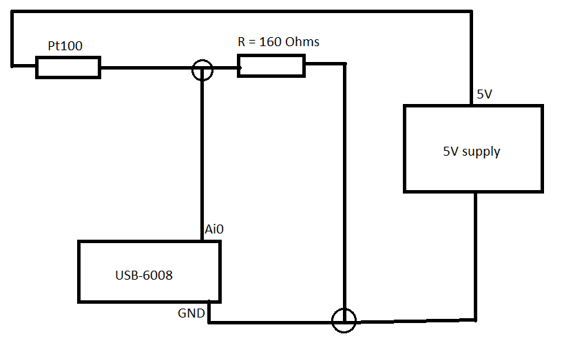
I'm using the hardware DAQ USB-6008 (I know that's not accurate and all) and I use the Pt100 (QAP2010, click for plug technique).
I connected it like this.
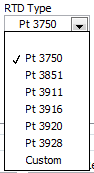
Now in LabVIEW, these are the only options (DAQmx new task-> acquire->-> RTD temperature signals).
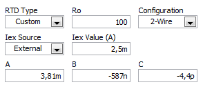
If I choose for custom settings, I get these options (I don't know what variables that is).
I use a small greenhouse where I need to measure the temperature and humidity and control environment (by using a fan to cool the cartridges to greenhouse and heat to heat).
My goal is to read the temperature using a graph on the front panel.
Can someone help me how configure/choose the right options? If you need more information I'll provide them as soon as possible!
A quick search for RTD class B shows the precision and the coefficient. As Fan Ravens stressed resistance according to the temperature is plotted in the data sheet. To control the temperature in greenhouse, a simple calculation of the slope of this graph is not good enough.
Note that the USB-6008 case limited an active player on the outputs analog and it controls only the voltage. So you will need at least one external resistor and possibly and external power to excite the RTD. These options that you have linked is not applicable to the USB-6008, which is a very simple device. You should perhaps simply to measure the voltage and calculate first resistance, then the temperature.
Lynn
-
USB 6008 digital output signal
I am VERY new to LabView and have been racking my brain trying to get digital output of my USB-6008. All I want is to be able to get a signal of + 5 V of my digital output when I click on a button. This signal opens a valve on a system I see so when it is pressed, it must stay open until I press the new button. It seems simple enough to me, but I'm not too familiar with LabView. Help, please!
Stripling07
You must first take the LabVIEW tutorials and then look at the links to get started with DAQmx .
The simplest program would be with the DAQ Assistant. Drop it on your schema, and then select digital output > digital line. Select the line when the wizard has completed, click OK. Wire a Boolean value in a table to build and the output of which is connected to the data entry. That's all. You can test the output of MAX (Measurement & Automation Explorer) with the test Panel. Do NOT test with your connected tap. Your valve may require more current that can provide the 6008.

-
NEITHER USB 6008 voltage offset using CSR and measurement of diff.
Hi all
I am currently trying the NI USB 6008 housing and I'm getting problems when reading voltage analog using CSR or differential.
So basically, what I want to measure is a PWM signal (0 to 12V), which is divided by a divisor of tension (by two). But instead of measured 0V and 6V
I am in a position a constant 0.8V and approximately 3V.
On the side of digital data acquisition, I give you on impulses for the SSR... and it works fine.
I connect it that way: http://digital.ni.com/public.nsf/allkb/95CC0CB11D7DF3D18625712E000C4ABD?OpenDocument
Would apreciate any help
Best regards
EDIT: Attached graphics acquired are
What is the impedance of your voltage divider? The input of the USB-6008 impedance is not very high. If the impedance of the partition is large, it could cause the effect you see.
Lynn
-
Want a ramp of output voltage over time and measure input 2 analog USB-6008
Hello
I want to produce an analog voltage output signal that increases over time with a certain slope, which I'll send in a potentiostat and at the same time I want to read voltage and current (both are represented by a voltage signal) that I want to open a session and ultimately draw from each other. To do this, I have a DAQ USB-6008 system at my disposal.
Creation of the analogue output with a linear ramp signal I was possible using a while loop and a delay time (see attachment). Important here is that I can put the slope of the linear ramp (for example, 10mV/s) and size level to make a smooth inclement. However when I want to measure an analog input signal he's going poorly.
To reduce noise from the influences I want for example to measure 10 values for example within 0.1 second and he averaged (this gives reading should be equal or faster then the wrong caused by the slope and the linear ramp step size.) Example: a slope of 10 mV/s is set with a 10 step size. Each 0.1 s analog output signal amounts to 1 mV. Then I want to read the analog input in this 0.1 s 10 values)
Because I use a timer to create the linear ramp and the analog input is in the same loop, the delay time also affects the analog input and I get an error every time. Separately, in different VI-programs (analog input and output) they work fine but not combined. I searched this forum to find a way to create the ramp in a different way, but because I'm not an experienced labview user I can't find another way.
To book it now a bit more complicated I said I want to measure 2 input analog (one for the voltage of the potentiostat) signals and one for the current (also represented by a voltage signal) and they should be measured more quickly then the bad of the analog signal. I have not yet started with because I couldn't read on channel work.
I hope someone can help me with this problem
An array of index. You want to index the columns for a single channel.
-
NEITHER USB-6008 connect to thermocuples and pressure sensors, control valve
I am endevoring to build a gasification plant biomass for bench scale test process control plans. NEITHER USB-6008/6009 will be adapted for use as a data acquisition. I'll take RTDS, thermocouples and pressure sensors. I don't want to use industrial automation controllers. It is also possible to use the channel of analog output for sending signals to a control valve position (using sufficient current/voltage between the two drivers).
(1) OK. I just wanted to be sure that you were aware of the potential dangers.
(2) an RTD is a resistance that has small changes in resistance per degree of temperature change. To measure that you have need of a current source and a sufficient resolution in order to detect small changes. At 25 degrees C a typical RTD is 109,73 ohms and resistance ohms 0.38 per degree changes. If you had 1 my crossing this RTD voltage through it would be 109,7 mV and the voltage change of 0.38 mV by degree.
The resolution of the 6008 on the most sensitive range is 0.49 mV > 1 degree. The accuracy of the 6008 is 1.5 mV typical.
For a Type K thermocouple, voltage at 25 degrees is 1.407 mV and change by degree is 39 µV. Millivolt solving half of the 6008 translates into about 12 degrees.
If you need a source of excitement for RTD and a kind of amplification for thermocouples and RTD before she would make any sense to try to use USB-6008.
(3) I have not used anything except LabVIEW with DAQ devices and drivers. I think DAQmx can be used with MATLAB and other languages.
(4) the 6008 is the low range made by NOR. You will need to go to a more expensive camera or add signals conditioning circuits. Talk to your representative OR assistance in the choice of a suitable device.
Lynn
-
USB-6008 LABVIEW 8.2. SINGLE CHANNEL WITH DBL INPUT VOLTAGE OUTPUT COMPARISON
I AM WRITING A PROGRAM THAT USES A SIMPLE USB-6008 ANALOG INPUT CHANNEL. I WANT TO READ CONTINUOUSLY THE VOLTAGE FOR 60 SECONDS. I WANT TO COMPARE A TENSION FOR THE PREVIOUS OF THIS SAME CHANNEL VOLTAGE, MAINLY FOR THE PERIOD OF TIME MAX VOLTAGE GIVEN, THEN GET A FINAL VOLTAGE READING. THE OUTPUT OF THE VI IS A DBL. I WANT ONLY TWO TENSIONS OF EXPORT TO EXCEL. TO SAVE TIME, I KNOW HOW TO EXPORT. CAN SOMEONE HELP ME WITH THIS ONE.
VI needs an register shift related to the Max & Min function. The current value would be the entrance is and the entrance of x is the left shift register. The max value gets wired for the shift register to the right. Don't forget to initialize it. The output of the shift register is the max you would write and the value of the DAQmx Read out of the loop of wire will give you the last reading.
Your waiting for 45 seconds makes no sense since you said that you wanted to read continuously. You also said that you wanted to read 60 seconds and all this logic is missing. A simple function of time elapsed, it's all you need.
-
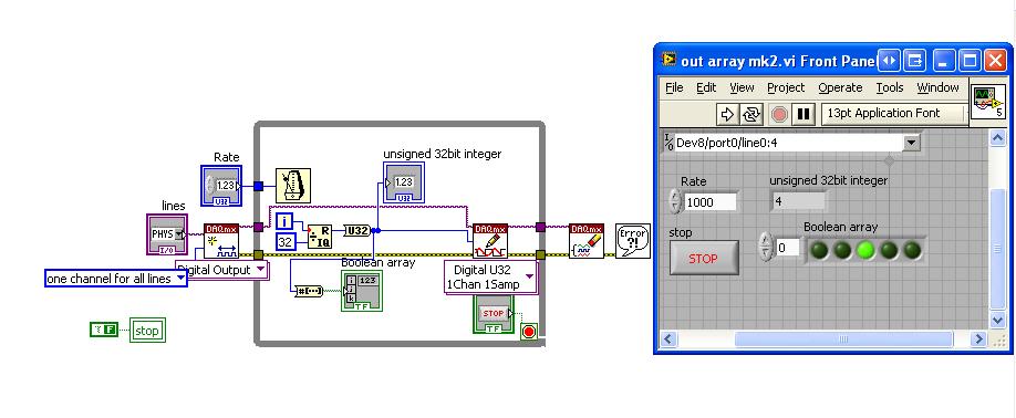
Generate a binary sequence with the NI USB-6008
Hi all
I'm new to LabView and I am trying to generate a binary sequence with a box NI USB-6008. The sequence, I'm currently generate is a counter of 5 bits, i.e. 00000 00001 00010, 00011... 11110, 11111 placing each bit in a different digital IO of the of the 6008 NOR, so that I can use the County as the bits of selection in a decoder/demux.
I managed to simulate the binary sequence and produce a graphical interface, but I have not found how to generate the sequence of bits with the NI 6008.
Totally, I'd appreciate any help you could provide. Thank you very much.
Hi JosephM,
Good Afternooon and I hope your well today.
I just tested the code on a 6008 and also released the above code is very complex - I was for some reason any fixed on using Boolean tables.
Please see the attached code, in LabVIEW 8.6.
Mind you, I have configured the task as a channel for all lines. i.e. digital single I spent, is the task value should apply to all channels selected in the entry. So if you select only port0/Dev8/$line0 for example, the DAQmx driver will examine the LSB of the digital and work so $line0 must be true from the false. It will NOT update all other channels. So when I select line0:4 - it will update the first 5 lines (bits) in digital. As the code generates a number from 0-32 he emotional generates 00000 to 11111.
I hope this finds you well and sorry for the first post!
-
Hello
I have a USB-6008 read a signal to 5V on one of DIO ports. The 5V is or the circuit is open. Since the 6008 traction has internal open ups resembles a true TTL signal. I think using a 850 Ohm pull down on the output line. I think that should lose about 5.8ma when the 5V is present. 6008 for line specification is 8.5ma. The 5V is coming from a mechanical switch which is activated when the vacuum is applied, so that the switch does not consume all current... It seems to me that it should work. But............ Does anyone see a problem with that?
Thank you
Alan
Connect the switch to the Gnd and reverse the bool off the DAQmx Read?
-
Hello
I am currently using a map of measurement computing USB - DAQ 3101, but now uses a card DAQ NI USB-6008 and need a bit of help with conversions of connector and pinout. MC USB-3101 has a pinout 56, where, as the NI USB-6008 housing has a pinout 32. I've done the research, but found different results. Someone at - it a concrete conversion pdf or Web site for these conversions?
Thank you
Hello Steve,.
Thank you for your email back! I now see what you were asking. The VOUT1 and the VIOUT2 I feel would be the equivalent of the 6008 AO 0 1 AO and GND. So pines 14-16 These would be the pins that you would use to produce a voltage based on the specifications of the card. It is not a "NC" or not connects to the 6008, as all the pins are used. Let me know if it helps! Have a great day!
See you soon!
Corby_B
http://www.NI.com/support
Maybe you are looking for
-
The PCI-6052e does support I2C or SPI communication?
Currently, I am trying to build a data acquisition system to test, among other things, SPI and I2C devices verification of characteristics and surveys of behaviour without advertisement above the different temperatures. The DAQ card that I use is th
-
Photo printing choose the wrong device
I have a printer that is also a fax machine. When it has been configured, it created a printer id and a fax number. I set the printer as the default printer and it works very well when printing documents. However, when I print a picture it automatica
-
BlackBerry 8830 smartphones and headphones
I bought an adapter for my headphones to listen to music on my 8830, but it plays only on one side. I tried different adapters, headphones, and same 8830. I do not have a headset with my 8830. What is the solution?
-
I have an Adobe [deleted by Moderator] order number for a 12 month plan.When I use PHOTOSHOP says my trial version is soon exhausted. But when I connect I need a number of redemption. How can I find my redemption number?
-
Adding new hardware that is listed in the HCL
I want to add a network adapter that is listed in the HCL to the ESX 4 server, esx install this card automatically for me?