Measurement error Freuqency
Hello.
I have a VI whose frequency records 4 channels for a NI9411 and generates a string of adjustment 0 - 5V. It works fine apart from when there is no siganl current frequency.
When my rig is first turned on there is no current frequency signal and after about 10 seconds, I get the attached message.
Is it possible to modify the Vi (attached) so I do not get this error in the future? I can't guarantee that it will always be a frequency signal.
You can set the timeout to-1 in this way he'll wait forever.
Tags: NI Software
Similar Questions
-
Measurement error of the County of edge by using the external sample clock
Hello
I'm trying to measure the number of edges (rising) on a square wave at 5 kHz with a generator function on a device of the NI PCIe-6363. I configured a channel of County of front edge of counter at the entrance of the PFI8 device. I use an external sample clock that is provided by the output of the meter of a NI USB-6211 housing channel. If I acquire for 10secs then ideally I would expect to see a total of 50000 edges measured on the meter inlet channel. However, my reading is anywhere between 49900 and 50000.
When I use the internal clock of time base to measure the edges, the measure is accurate and almost always exactly 50000. I understand that when you use the external sample clock, the precision of the measurements is subject to noise level of the clock signal. However, I checked the clock signal is stable and not very noisy. Any reason why there is an error of measurement and how tolerance should I expect when using an external sample clock compared to when you use the internal time base clock?
Also, what is best clock Frequency (with respect to the frequency of the input signal) when using an external clock?
Thank you
Noblet
Hi all
Thanks for all your sugggestions. I was using an input signal with a function generator which had a range of 8V. It turns out that the reduction of the amplitude to 5V solves the problem. I was able to get accurate numbers with the 6211 external clock.
Thank you
Noblet
-
Period measurement error 20308
I'm trying to measure the period of a very slow rate (Hz 0,083) to come to my DAQ (6009).
However, it comes with "error-20309 occurred at the" NI_MAPro.lvlib
 ulse measures 1 chan.vi:2 "when it is called of" NI_MAPro.lvlibulse measures N chan.vi:1 "(waveform index 0 1)". "
DQA captures method is set on "on demand" however I also tried various (frequency + buffer) such as 10 k by 2 k.
but it always comes up with the error.
I know why it comes up with this error but do not know how to fix it.
I have attached the vi (the signal to simulate reply my DAQ)
Because you'll probably want at least 2 cycles whole to your measurements, and each cycle lasts approximately 12 seconds, I would get 25 seconds of data at 50 Hz (1250 samples)
-
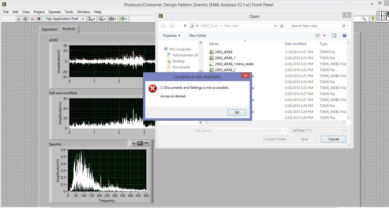
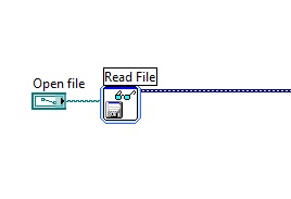
measurement error filename file
Hello.
In my project, I used the function to read the file can read the .tdms file. When I run the program on another folder or on another PC, and then select the name of the open file, an error occurred, error window appears. Although there is no bad program operation, but it is very uncomfortable. So I hope how this error window does not appear?
Thank you.Your default path is "C:\Documents and Settings\user\Desktop\Save file\test.lvm". If you are on a Windows 7 computer, this folder does not exist. It is now "C:\Users\user\Desktop\Save file\test.lvm" (assuming you want this file to the desktop). As the search begins in the record of the value of current path, you get the error. Change your default path to something that is valid.
-
hp450c media in an attempt to feel measured error
I get a media error light when I press the 'leap' and the 'Reprint' button to print a calibration page.
DesignJet 450 c
Win XP
Media error
Thanks for the comments.
However, I need not post the question because I came across the answer. I found it by trial and error that I needed to use the largest sheet size E. When I tried 8-1/2 X 11 and 48 inch rolled media I got a flashing of media.
I'll try better in the future to post in the right group.
Jerry Clasby
-
vCloud 3.3.3 consumption measurement error
Hello
I get this error message... I do not exactly know the meaning, is at - it can someone help me?
On the use of meters (192.168.x.x, b 2% fe80:0:0:0:250:56ff:fe96:554), a collection of server077.root.local, started the 2016-02-20 23:05 failed to 2016-02-20 23:06:24. com.sun.xml.internal.ws.client.ClientTransportException: transport HTTP error: java.net.UnknownHostException: server077.root.local
This is the DNS issue. Unable to solve vCenter server server077.root.local UM. Can you please add vcenter server entered the vcloud use counter server host file FULL domain name or use IP address instead of FQDN vCenter?
-
Can we average channel error using multiple channels to measure the same voltage?
I don't know how correlated error terms are between measuring channels max, but it occurred to me that, if they were relatively independent, I might be able to sample the signal even with several channels and increase accuracy.
For example, rather than measure a voltage with an AI only at 100 kHz, I could connect up to 10 different lines to HAVE the signal, sample to 10 kHz on each line. This should allow to reach me on average some of the error associated with each channel (, or so I think).
Can someone speak definitively to this?
Thank you
Sean
Well, if you are using a MULTIPLEXED Board (everything is not specced for simultaneous sampling) then each channel is connected to the ADC even one after the other, best that you would be able to do is extremely, extremely small variations into the paths of each channel of the multiplexer. This would still be massively overshadowed by the inherent noise from the system and the accuracy of the device.
Your best bets to reduce the measurement error is to oversample in one way to reduce the effects of noise and to calibrate the unit before starting each test to keep variations of temperature. In addition, make sure you keep your calibrated Board (most of the boards have a calibration 1 year of the cycle).
For some applications, you should also consult wiring field and considerations of noise for analog signals, How to eliminate ghosting of my measurements? and Troubleshooting unexpected tensions, floating or crosstalk on Analog Input Channels to better account for ghosting and the issues of the hour.
-
High speed continuous measurement of encoder with sampling frequency of 1 kHz
I am able at all times the position of a linear encoder using a PCI-6602 counter card, and I need to know how to set up so that the counter rotating at high speed, but the data is inserted into the buffer at a frequency of 1 kHz. I am able suddenly to a hydraulic cylinder, and I am not concerned about the event recording to high frequency except to the extent where they throw off the number considerably if the equipment does not run fast enough to detect all the impulses of the encoder.
Now, I think is that the external sample clock signal control (routed internal pulse output counter) time rate whereby the equipment detects the impulses of the encoder and the rate at which it inserts data into the buffer. With a pulse 100 per inch encoder and a sampling frequency of 1 kHz, the extended final position of the cylinder is turned off by +/-0.15 inches, which is unacceptable.
I need calculate a speed of this information, so I prefer not to use software timed sampling to control this (it's more difficult programming for other reasons as well - several asynchronous measures). Any ideas on how to configure the hardware to count faster than the speed at which she inserts counties in the buffer?
OK, you're clearly on the right track here, so I will focus on some details.
1. How do you know that the +/-0.15 "differences are * measurement error rather than * error of movement? Why wouldn't be an accurate measure and a proposal which can vary slightly from the nominal value?
2. I wonder some all electric noise and defects that may produce false edges. The fact that the behavior was better by using a sampling rate limited (200 kHz) in the digital inputs may be that some of these flaws were so short that they were never captured.
I did a ton of work with the Commission to 6602 encoder and I can certainly confirm that count equipment is sensitive to the edges in a few tens of MHz. (I know its 80 MHz for edge counting, but I think I remember that it can be of the order of 20 to 40 MHz to accommodate the time of signal propagation extra of the quadrature decoding circuit).
A small point of clarification. You're talking about the speed at which the meter "works to. The value of count is a register whose value is changed completely by the circuit, * independent * of the sampling frequency. If you enjoy with material-clocked County in memory buffer or interrogation of software without buffer not a bit for circuits that increments / decrements the value of the counter register. (In other words, I am completely convinced that you would get commensurate with position end even if you took only 1 sample software-polled after the end of the move instead of sampling at 1 kHz all the way through.)
So, if the value of the counter is disabled, it is because the circuit detects producers of County of the edges that shouldn't be there. Something you can try is to set up digital debounce filter for input lines of the PFI corresponding to the encoder Source inputs and to the.
-Kevin P.
-
Analog inputs measures with NI6229 using the DAQmx driver
Hello
I have four different analog inputs connected to ai0 to HW 6220 ai3. I read these values with a single task, all 4 channels assigned to this task. When ai0 reads 7V, I see 0.8 V ai1 too, but I expect to be measured 0V. If I just assign ai1 to the task and measure all 4 channels, then I measured 0V as expected (although ai1 contains 7V, I just don't measure it).
Another comment 'funny', is that if I change the order in which I add channels to the task, measurement errors are different.
However, when measured with a multimeter 4-channel show tensions as expected.
Given that my calling task is can not block, I call the function
DAQmxReadAnalogF64 with timeout = 0 and numSampsPerChan = 1.
Any help is appreciated.
Thank you
Kind regards
Deepa
Deepa,
Thanks for the code snippet.
When you call DAQmxReadAnalogF64 the first time and you set a value of timeout of 0, there is a chance that the acquisition is not yet initialized. This is the expected behavior and should not be a problem. If the timeout error died at the first call, you might ignore it or set a different expiration time for the first call only. In all cases, you should drop the first value and start with the second value.
Jochen
-
with WSN Vernier temperature probe?
Hello everyone. I have a hard time trying to get the sensor measures.
I created the thread here: http://forums.ni.com/t5/LabVIEW/steinhart-hart-with-vernier-thermistor/m-p/2811150
I think that now the formula is fine. So I realized, it could be that I chose the wrong node to work with probe thermistor based.
So now I took node voltage/resistance NI WSN-3226. I don't know how to wire properly. EX0, AI0, and GND.
Any help would be so awesome. Thank you
Nicely,
Poor
Poor Hello,
That's right - you get a voltage scale out, not a resistance value. The manufacturer has provided additional information on the use of their probes with different here:
Vernier: Can I use BTA Vernier sensors with another of A - to-D converter?
http://www.Vernier.com/til/1952/?keyword=WRT-BTA
In addition, it seems that there are already example screws provided making this conversion voltage - to-resistance to-probe. I have found these Vernier website with terms like "ELVIS", "BTA-vehicles" and "reduced the tension.
Vernier: Why is the temperature sensor read correctly with my NI ELVIS
http://www.Vernier.com/til/2925/?keyword=BTA-ELV
NI.com: Interfacing screw for Vernier biosensors (download of example provided at the top right)
http://www.NI.com/example/31019/en/
The VI "convert thermistor rdg" provided in the zip file seems to apply Ohm's law to determine the resistance of the thermistor of the acquired power, as you have noted.
As a note - all this information was already available on the Web site with a minimum of research NOR and Vernier. It's probably a good thing to consolidate this information in a single thread/place so that future users have access to it (that's why I'm a link everything), but by doing some research on your own or contact the manufacturer directly could have you up and running last week! In addition, you must be sure that you understand your sensor and conditioning circuit before using the computer, do not understand what is happening is a good way to end up with measurement errors.
In addition, you plan on leaving the WSN node attached to a Committee of ELVIS for the acquisition?
Best regards
-
Variation of thermal EMF of the PXI-2530 modules
This message/question is a companion of my the most recent message in another thread.
In addition to watching some resistance higher than expected that affected current measurements using modules PXI-2530 multiplexer 4W topology, I saw systematic variation in track-to-track blood pressure measurements. Tensions would increase gradually through the 16 channels in a configuration by measuring the voltage at the terminals a resistor 1.5 kOhm with 0.5 au crossing (75 uV). I've identified that the thermal EMF of the reed in the PXI2530 module switches is on the same order of magnitude of these measures and set out to quantify the differences EMF thermal track-to-track between my three modules.
Test method: I have a TB-50 which is configured to mux the signals of tension for a DMM. I connected each of the four DB-50 one cable of 176 pins to this block and collected with a PXI-4071 pressure readings set to 7.5 digits precision in the range of 100 mV and > 10 GOhm impedance. For most channels, it took several minutes for the voltage stabilize - or at least appear that it was to stabilize.
I enclose three graphs. Note that the vertical scale is the same on each.
Data that triggered this survey was collected with MUX1, via connector P2 to voltage. The magnitude was not quite the same-probably related to the phenomenon of stabilization time, but obviously the worst group of channels three multiplexer modules.
The three modules were all bought at the same time (about 2 years ago), but had only limited its use in the first year or more. The three now have various 'mileage' based on my use. But MUX1 clearly behaves differently two other modules. The
I changed my test conditions to spend 0.5 au via a higher resistance to thermal EMF less important. The PXI-2530 sheets indicate that thermal EMF must be less than 50 uV. In most of my measurements, it is. But not for MUX1!
Any thoughts?
Thank you
Jeff
Hi Jeff,
You can check that all the three modules are PXI-2530, not PXI-2530 b (while, as the PXI-2530 b parts slightly higher thermal emf)?
Specification of emf thermal 50uV of the PXI-2530 is a typical value, is not a guarantee of spec. See a few channels higher than the spec is not a cause for alarm, but it shows that we must take account of this in our measurement error. Note that the industry standard for the technical measure thermal emf is to close the relay, wait a few minutes and then take a measure of tension. For example, if you scan through a switch faster than a relay per minute or so, the thermal emf will be less predictable and stable. A single module performs worse at these low voltages is not indicative that this module is a failure, etc. the module is fine. Unfortunately, the reed relays have more emf thermal relay of the armature, mainly because of the many layers of metal in a Reed compared to a frame (each metal junction is a source of emf if these metals are not the same).
Thermal EMF is proportional to the temperature, it may be interesting to note the position of the chassis of the less powerful module. Placing hottest modules (scanners, Ara, RF, etc.) will reduce the thermal emf.
-
Confidence in the PSC - tc interval
Hello
We measure the temperature with thermocouples connected to a cFP-TC-125 module. I am interested in the accuracy of the measurement of this unit. Of course, I know the patterns in the manual, containing different measurement error curves for different measurement situations. For a specific room temperature and the thermocouple, there are two curves. It shows a so-called 'Max' and the other a measurement error "type." I understand the difference, but we want to use the information to calculate the total measurement error (which also contains the error of thermocouple sensor and different error from an average of measurement points). Well, I got to a point: If you add up different measurement error you must use the same interval of confidence, because it is the scale of the measurement error.
The question is, if someone could tell me what confidence interval not 'Max' and 'Type' belong. What 1sigma, 2sigma, 3sigma? In a first approach, I would think that "Type" is 1sigma and 'Max' is 3sigma. But, assuming a normal distribution or a uniform, this does not seem to fit the data curves.
Thanks for reading, cordially
Gerald
Hello
I did some research and I can answer your question:
Figures for the errors of different thermocouples use values for margin of error / error page 15 the same manual calculate typical (15-35 ° C) and maximum (40, 70 ° C).
And I have confirmed that these maximum errors indicated in the manual are taken at the 99% confidence interval, script readings the worst.
I hope that this answer to your question.
Good day
-
Analog input problems using PXI-6232
I tried to solve this problem for a while now without a bit of luck. Solution suggestions are welcome.
I use a PXI-6232 with LabView 8.5.1 to accept signals analog several of my sensors. Based on the signals as a PWM signal is generated and the output using PXI-6713.
Some of the analog input signals have spikes in them, which occur at all times during the tests. I watched the same signals on an oscilloscope - without crampons. I change my hardware configuration, and the spikes still occur in the same places. It seems that the program makes some resets resulting in measurement errors.
I have attached the VI and a JPEG of measured inputs.
Thanks in advance
Concerning
Vadim
I was first confused of your time scale
 but it seems that these spices occur every 20ms (not s) what to a line 50 Hz noise due to switching power converters (or a diode without compensation bridges
  )
)Another clue was the measure of the scope. While using the application scope, you opened a groundloop so the spikes because of the dI/DT through the groundloop are another way to get around.
So I'm pretty sure this isn't data acquisition (in this case) this is your configuration.
Provide a cleaning (low R AND L low) path of power (keep them close and twist slightly if possible), add a filter to down the dI/dt, identify the ground loops. (Use your scope with a little as a sensor at the entrance to reel and catch magnetic fields can open eyes)
THEN to clean the last ears (on the acquisition of data) to get the last ppm use selfs
-
How low is low wrt LowFrequencyOneCounter
We want to measure the period using CIChannel.CreatePeriodChannel (). The pulses to measure are to about ~ 220 Hz. What is a frequency too high? Obviously, we would like to avoid using two counters for this, if we can avoid.
Nathan
Hi Nathan,
The method of low-frequency account database internal time of known frequency for a period of your input signal. We can then say the period of your signal input with a resolution of ± 1 period of the time base. This result is reversed to get the frequency of the signal.
The reason that the method is called "low-frequency", is that it is not suitable for frequency signals higher where 1 graduation of the internal time base would represent a significant percentage of the period of the signal.
Depending on your hardware, you would have a different basis of time available. For example:
E series: 20 MHz, 100 kHz
M series: 80 MHz, 20 MHz, 100 kHz
X sereis: 100 MHz, 20 MHz, 100 kHz
Assume that a map of the E series using the time base of 20 MHz.
Input signal: 220 Hz
Period of the input signal: 4.5454545... Ms (1 / 220 Hz)
Base period of time E series: 50 ns (1 / 20 MHz)
So, for each period of your input signal, you will have about 90 k timebase ticks (4.5 ms / 50 LV). Given that the resolution of the measurement is 1 timebase tick, it gives about 11 ppm the measurement error (1/90 k) at frequencies around 220 Hz. For most applications 11 ppm should not be a problem (for example instead of 220 Hz 219,9978 Hz). Many new DAQ (M or X Series) cards have a faster time base that would give an even smaller error.
Given that the accuracy of the time base of the multifunction DAQ cards more is of the order of 50 to 100 ppm, the 11 ppm of resolution of the measure will be probably adapted.
For more information, the X series user manual has a section describing the accuracy of the different methods of starting on page 7-18. The "Quick sample" method applies only to new equipment as the X series, but other information should focus on most of the other DAQ cards.
In short, 220 Hz is generally not a frequency high enough to justify the use of one of the other methods. The exception is if you use a Board with a very accurate oscillator (e.g. 6608) and are looking for more specific as possible (e.g. for calibration purposes).
Best regards
-
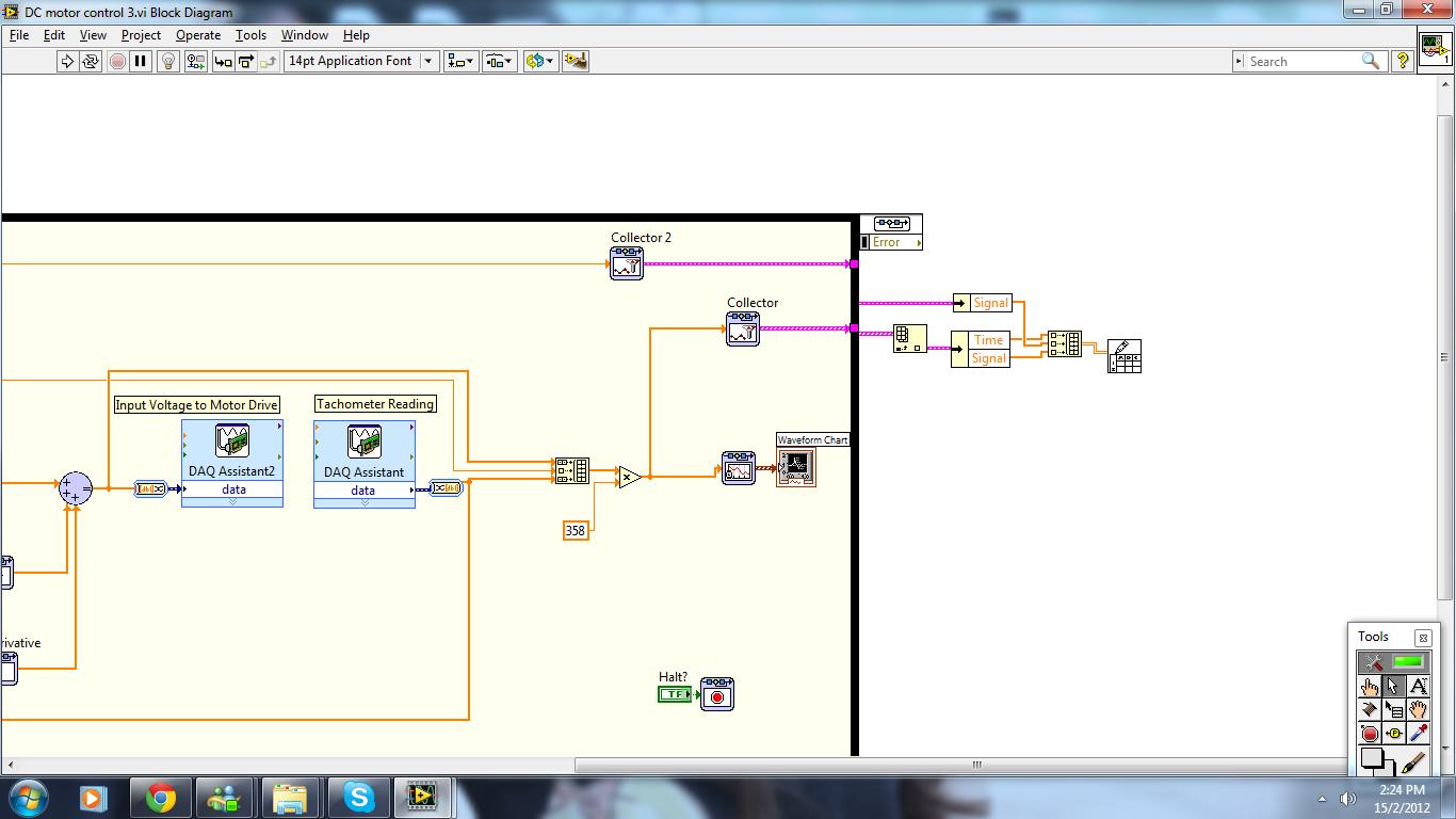
Problem of Simulation collector design & control
I try to work on a collector in the simulation loop control & design but I found that there is a problem
1. the data that I collect takes horizontal form, how to change the data of horizontal to vertical?
2. the data that I collect does not move to the actual speed, has collected data in the wrong thread? Please correct me if I got hurt.
Thank you very much

Yuki
For the rotation of the table, you must use the function "Convert 2D table" to the title of programming > table Palette.
For the second question, I don't know what you're saying. What do you mean when you say "don't move to the actual speed? Do not control? Narrowly on measurement error? Delay?
Think it is important to check to see if you have the engine as "Runga Kutta 1 (RK1)" since you are trying to control the real system.
Maybe you are looking for
-
What can I see on one page to know that this new private page has been activated
I know that 'new private window' works on my computer because if I go to the history, it is empty, there is no sites listed after going to various websites. So I can always check it out like that, but I was wondering if the page I'm would give me an
-
Toshiba 48L1433DB - USB timeout problems
My USB Ports do not appear on my list of Source and I have a problem of "dead time". If I put a stick in the media page loading USB ports and everything works perfectly, but then turns off after an hour or two (the on-screen message shows empty port
-
Evaluate the crash report? LPX crashes on load suddenly.
This morning I finished a track. Now I can open a blank project, okay, but in previous projects which who was good this morning. Crash at the end of the charge cycle. Out of ten loading tests of another project that has been recently very well, I ha
-
Purchase XP Antispyware problem
I tried four times to buy this 'XP Antispyware 2012' and gave al my credit information... BUT EVERY TIME HE TOOK THE INFO AND THEN GAVE ME THE MESSAGE SPYWARE INVASION, IT NEVER DOWNLOADED. I DON'T WANT TO PAY FOR THIS SOFTWARE! HE'S NEVER WORKED BU
-
HP compaq 15 h000na: can't get back into windows after installing windows 10 [attention] 8?
Microsoft and hp did an automatic installation of windows 10 and that my old system was windows 8 Andi want to return because the internet explorer 11 is now 64-bit and Windows 8, it is 32-bit, this i where the problem is, a lot of sites do not suppo