Measurement of current with NI6250
Hello
I use the 6250 OR for certain analyses of analog input. In addition, I want to measure the current that I supply to the unit under test. The current is about 300 my.
I thought to use a shunt at 2 ohms resistance, so lowering the supply voltage of 0.6V and not having not too low-voltage measures. I intend to adjust the votage of 9.6 V power supply to get 9V after the shunt resistance, because I'm supposed to provide.
1. any comments or better suggestions for this?
2. I will calculate the current by measuring the voltage on the resistance. The question is I will use 2 unique inputs or differential input?
3 you are looking for in table 4-3, page 4-12 of the M Series DAQ - user manual, I see an application of a differential input voltage. There, they put 2 pull down of the resistance to Earth. I do as well? Can't I just apply the 2 lines of resistance, directly at the entrance of diff?
4. am I suppose to connect the ALWAYS to my power supply GND?
Thank you
Rafi
In your case, the differential is the way to go. You don't need resistance more bias from (drop) current if your PS is connected to (A) MASS somewhere anyway.
Tags: NI Hardware
Similar Questions
-
measurement of current with usb-6009
Hi, my name is hung and I am a student in electrical engineering... I'm doing a thesis that the project using Labview and acquisition of data NOR UBS-6009 to simulate the function generator, Oscilloscope, Digital Microsoft (DMM)... and now I'm simulating DMM. I managed to measure the voltage and resistance which i use voltage divider method, but I encountered a problem with the current measurement. The problem is the USB-6009 to measure use the current, it measures an incorrect value. I tried to use the current CQI 0-20mA Sample.vi example but it always measures an incorrect value. If NI USB-6009 supports for the measuring current? Is there a way to measure the currents using USB-6009? Please, help me. This thesis project is so important for me. Thank you.
Hung,
Since you are a student in electrical engineering, I'll show you how to know the answers to your questions.
1. review the specifications for the USB-6009 case. In particular look at the specifications of analog input.
2. How would you measure current if you had only a voltmeter? Use the same method with the USB-6009 case. (Tip: apply the Ohm's law).
General comment: when using any measuring instrument, always consider maximum permitted values at the entrances so that the instrument is not damaged
and the measure is accurate.
Let us know how you do.
Lynn
-
Measurement of current with NI 9219
Hello
I'm trying to measure using NOR 9219 & nd continuous current cDAQ, also I'm using a multimeter to ensure that the current value remains within a range of +/-25mA, the problem is that I am getting the value on the multimeter (0-20 my) and not in the measurement and automation (0-2 my!), which can be the cause of this?
Best regards
MGarry
the problem is connected over connection, nothing to do with the material or the Meusurement and automation.
-
measurement of current with usb6008
Hello
I use a PMT detector whose output signal varies from 0 µA to 100 microamperes, but must remain lower than 100 µA. I put a 100 kilo-Ohm resistor in the line signal and, using a voltmeter, I can measure the voltage at the terminals of the resistance and calculate the current. I would replace the voltmeter with my USB6008. However, when you use a differential pair of channels to measure the voltage on each side of the resistance, the current wells USB6008 and affects the signal.
Is there a way to measure current without affecting the signal?
Kind regards
Oliver.
Oliver,
The 6008 sheet indicates that the AI input impedance is 144K ohms. Far too low for what you're trying to do. If you're stuck with the help of the 6008, I would consider using an instrumentation amplifier (AMP02 comes to mind http://www.analog.com/en/amplifiers-and-comparators/instrumentation-amplifiers/amp02/products/produc...)
to build a celled amplifier with a gain of 1 to act as a buffer. Input high impedance which does not load your source microamp, a lot of training for the 6008 entry.
-
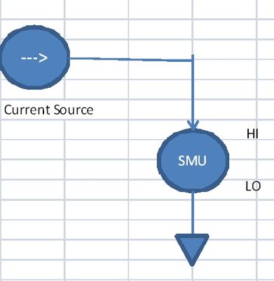
SMU, used for the measurement of current
Hello
I need to measure current in the range 5 to exit 10uA by a current source PIN. I would have usually connected PXI4065 on this PIN and measured current. But in this case the current to be measured is low.
I have EMS 4130, which has high accuracy of current measurement to 200mA range (0.03%+0.02)uA.
Can I use the current part of the EMS (CH1) measurement to measure current? What should I activate CV outputs (Hi = 0V) who appears in the soft front panel?
Or just without activating the outputs I can measure the current sink. The program of flexible panel displays current measurements, but I don't know if the EMS can be used like that.
Thank you
Not sure NI SMEs, as I have not had the chance to use it yet. SMU of Agilent could be used this way, so I guess with OR as well. You must use out SMU in constant voltage source / I measure mode. Would you say the SMU to hold the voltage at 0V, and allow current to the sink (or source) as necessary to maintain this 0V output.
-
Measurement of current and voltage USB-4065
I have an application where I need to measure the direct current and the voltage. The current and voltage will be stable if the measures do not need to be simultaneous. I would use a USB-4065 to the two measures. I've seen the kb indicating the voltage inputs must be disconnected when the measurement current. The current inputs must be separated for a measure of tension?
Hi Collin,
I think that you are referencing this knowledge base. After a few tests, and worked with the R & D group, it seems that the effects of input connections are perceived during the passage of two ways. When the current entries are connected, a less accurate voltage reading occurs. As such, please disconnect the current inputs for a measure of tension (as well as disconnect with tension when taking a measurement of current entries, who you know).
-
Measure the resistance with PXI DMM 4072 on different frequencies
Hi all
I tried to get on board various and unable to find solutions for that. I'm trying to measure resistance using NI PXI-4072 on frequencey 1 kHz, but not luck. When I try to use Agilent LCR meter I see the correct value of the resistance.
I've seen a few posts on this but don't have no satisfactory solutions.
In above post, someone said that I can use 4072 DMM OR digitizer, does not have a lot.
Can someone please provide the right path for me to solve this problem.
Thank you
Hello Puneet_K,
I checked the data sheet and the method of measurement described in the specifications of the NI 4070/4072 http://www.ni.com/pdf/manuals/371304g.pdf; indicates that the ability is measured using an alternating signal and select the test frequency range, for example 3 kHz, 1kH or 91 Hz. The resistance is simply measured using a DC signal, and it is often sufficient to measure the internal resistance of a battery. If you need a more flexible control for the measurement, you probably get a card like the function generator and then set a multimeter to measure the voltage and another DMM to measure the current and calculate the impedance of these values.
I hope this helps!
Kind regards
-Natalia
-
measure temperature pt100 with cRIO9211
I can measure the temperature with a pt100 in cRIO9211? I wanted to measure of 0 ° c to 100 ° c...
Can someone please show me how?
Thank you very much
Best regards
Hello
Thanks for posting your question on the forum of National Instruments.
Unfortunately, you can't have a RTD (generally with a PT100 probe) measure on a module 9211.
9211 module is dedicated to the use of thermocouples.
I suggest that you use a 9217 or 9219 rather (more information here).
I hope this answer will help you.
Best regards
-
I was converting pdf to word. I tried to download multiple documents, but the system froze. I closed the Acrobat Reader. Now, I see no export tools more. I even tried to restart the computer. I am currently with my account.
Hi bulldogcl1,
Please perform this cleanup tool to uninstall the reader Download Adobe Reader and Acrobat cleaning - Adobe Labs tool, reboot your system & install the latest Adobe Acrobat Reader DC Acrobat Reader DC Learn & support , sing with your Adobe ID to use the export to service PDF format using Acrobat Reader. Export PDF to Acrobat Reader DC.
You can also use this online https://cloud.acrobat.com/exportpdf service
Let me know if it solves your problem.
Kind regards
Nicos -
Need help with measurement excitation current OR 9219 Module
Hello
I have problems to find the answer to my question. My question is... How do you analyze the excitation of a 9219 module current? It seems that the excitation current which is specified (0.0005 (A) is not what is provided at the exit. With a load of KOhm 10.5 a 0.00025 current is output. As the resistance changes as the current and measured excitation voltage seems to change. I just need to know the resistance... So, if I can monitor the voltage and current I can calculate the resistace. BTW, why don't the current excitement remains fixed in the first place?
Thank you
Nate
Hi Nate-
In almost all modes of the 9219, the current and the voltage automatically adjusts to the load it experiences. The resistance is then measured according to the amount of current and voltage sunk by the load. This is explained in 9219 User Guide and specifications. The guide also States the the 9219 input impedance according to which mode it is.
I hope this helps. Good luck with your application!
-
Measures of current between 4071 and 2575 sometimes not correct
I use mode of handshake with a PXI-4071 scan list and an SMU-2575.
The DMM is current and the MUX is in mode 1 x 196.
When running the scan list, I have rarely (randomly) get a very small extent to the nA au (when to 4-20 MA). I'll run the scan list again and that the channel will be correct, so it seems not to match a channel.
I tried to increase the time of settling of the DMM and the MUX, but have had no effect.Any help would be great.
Thank you
Caleb Swieson
After further tests, we determined that it was indeed the devices to measure who pulled out the very low currents. So it wasn't the fault of the hardware. Oops
-
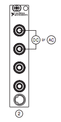
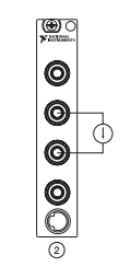
Measure the current and voltage using DMM sharing a port
I want to measure pressure several times on a pcb, where I connect the ports of digital multimeters to the card using simple cards. Switching between the different voltages is done using simple. If the black port of DMM (the second from the top photo) is connected to the Earth to give the measure correct volt.
And then I want to measure current through different lines. The problem is here. Given that two measurement types share a port, how do I get the correct voltage and current measurement? The second port of top would be grounded, so I can't use the method of measuring the voltage across the line through a resistance with a known value, since then the second port must not be connected to the ground. How can I use the current state of the DMM measurement? How measure current? Are there examples of this? Tried looking through manuals, but could not find the good starting points.
so I can't use the method of measuring the voltage across the line through a resistance with a known value, since then the second port must not be connected to the ground.
On all of my games to test I have to mux my land of the signal along with the salvation of my signals.
All my mux test sets are set up for the topology 2-wire because there is no other way to do it without the weak side of switch also.
-
Measurment LVDT DC with CompactDAQ
Hello
I am currently working with reading as a result of an LVDT for a project that the present model is the DC LVDT Omega LD620-25
According to the data sheet's model requires a voltage of 10-30 v and a maximum current of 25ma
http://www.Omega.com/pptst/LD620.html
with regard to the available data acquisition modules: the NI 9237 and the 9220 OR by using a module compactDAQ
as the NI9237 has an internal output of 150mW obtained maximum current is 15ma, simply use?
the 9220 OR will be used for the acquisition of data but provides no port of excitement!
as for the solution another I thought using an AC adapter / CC of normal 12Vdc 100ma with a variable pot or a circuit voltage divider to provide the necessary tension
but I have several concerns with respect to the Earth circuit. in this system, I will have two independent reasons!
What will be the best solution to connect the LVDT module to the 9220 OR and provide a source of external excitation?
Thank you
Hello ghattas.ak
Consider the NI 9218. It can provide 12V exictation to ~ 50 mA per channel and read 5 or output 10V DC LVDT. To use this excitement 12V, 9 - 30V power supply must be connected at the Vsup pins. As you said, you can also use the 9220 OR with external excitation. The NI 9237 measuring range of +/-25 mV/V does not cover the 5 or 10 v output sensor you.
See you soon,.
Izzy O.
Product Support Engineer
National Instruments
NI.com/support
-
Measurement of resistivity with MyDAQ on TEC ca
Hello
I would like to ask for advice: we would like to measure resisitivity Peltier-elements. If we use the DC method, due to the cell voltage-Seebeck effect, we don't get the value of the true resistivity. The common method to use the measure of ca in the case of these devices. I would like to know if it is possible to use a device of MyDAQ for this task? As a first approach do us not need more precision, it would be more as a test of 'broken-element' (there is usually a significant change in the nominal AC resistivity value indicated by the manufacturer).
What would be the best way to make a simple measurement? What if I use an analog output of the MyDAQ lets say at 1 kHz, and I drive the Peltier element with this AC voltage source? I connect a resistance in the series, and I measure the AC voltage on that drop. After the results, I could calculate the current and the resistance of the AC of the Peltier element? Of course, I choose a resistance so the MyDAQ can drive the network.
What is your opinion, where to start?
Thank you!
Sounds like a good chance to learn more about these devices. In these conditions, I would do the same thing: try with what you have.
A quick glance at the plug MyDAQ it is clear that the current of the AO is limited to 2 my. I probably set the zone of OCCUPATION for about 2 V and use 1000 ohms in series with the Peltier device. That will keep the current in the 2 limit my. Two lines of AI to measure the tension on fixed resistance and the Peltier device. Then, you can calculate the unknown resistance.
If you were doing a production test or did the measure with a DC bias, I advise to use a transformer to couple the AC component in the CC line. This becomes a little more complicated to implement, but has much to versatility.
Please post after you have tried and let me know what you found.
Lynn
-
Hi all
I have a VI that measures analog 5 separate lines (pressure sensors, thermocouples in temperature, etc.) and 3 lines of DI/O (for a coder angular step phaseB and IndexZ). I'm having a few problems (as follows);
1 trying to simultaneously capture the reading encoder and analog playback, I tried setting them up on the same basis of 100 kHz time although the encoder reads at a different rate from that of the lines of I which produces squewed data. So I tried to make the lines to HAVE it read at each rising edge of the pulse of the encoder, (this had to number 2). Is there a way to make the lines SO the DI/O on the same clock sampling or better still in the same job for DAQmx?
2. analog digital converter is too slow (ie the error that the previous conversion was not completed before a new has been tried), when trying to acquire 5 analog in different lines triggered by impulses from a line of digital IO ADC says its too slow, a work around that maybe? Currently, I have a different task for each analog channel, is the cause of the error? I should concatenate the strings in a single task maybe? (any recommendations on how that would be great).
I've been watching a lot of messages about the analog triggering from DI/O, although I don't think many of them have the same chassis and modules than me... I work with a NI 9201 (Analog In), NI 9401, and a NI 9213 all hooked to a NIcDAQ-9178.
As a plus for the previous post...
After the validation, I came across this very useful utility provided by NOR.
http://zone.NI.com/DevZone/CDA/tut/p/ID/11549
It describes the synchronization between the DAQ hardware. I guess that it is so a thread lost since the answers to my questions are answered in this website.
Nick
Maybe you are looking for
-
Time Capsule/Machine and my mental health
I approach insanity trying to untangle my time capsule. The Capsule is an A1470 with 3 TB. I've set up on the purchase in January with my MacbookPro also brand new - am I not lucky? It all worked well - wifi network, time machine - batch. At the end
-
I get errors from 2100... How and where should I go to clean. \ ?
Security check has shown that my computer has 2100 clear... running slow... How can I fix it?
-
Windows Security Essentials with Kaspersky Internet Security 2011
Dear Forum members I just received email from Microsoft on Windows Security Essentials installation, but I have Kaspersky 2011, which was given to me by my Bank, those two would work together or should I just continue with what I have. I also have fu
-
My HP 14-d010AU cannot detect wifi
My HP 14-d010AU cannot detect wifi. His type of wifi 802.11 is (I didn't type b/g/n, it is not mentioned). Windowws 8 OS. Model of wireless card: PCI\VEN_168C & DEV_0036 & SUBSYS_217F103C & REV_01 I tried to install a wireless driver, RTL8188EE REALT
-
DV7-4180us giving msg No. Boot Device or n, HDD, Win7 does not start.
Well, I think I've reached the beginning of what may be a serious problem. I've been away for 9 months and my laptop had been stored in his bag all the time not used with the battery disconnected. I went 2 weeks ago and it had been fine until last Sa