Ping between two VM
Hello
under Win 7 Professional, VMware Player 6.0.0
I created two Vm Machine.
BONES of VM1 is Win 2008 Server, NIC in Bridge, ip = 192.168.200.2
BONES of VM2 is Win 2003 server, NIC in Bridge, ip = 192.168.200.3
Default gateway for both is the same 192.168.200.4
They are in a working group and not in the field
When I ping from one to the other it fails with:
Request timed out.
Thanks for help.
Hello
Have you checked your firewall on your two virtual machines? Try turning it off.
Kind regards
Julien
Tags: VMware
Similar Questions
-
PowerConnect 6224 VLAN created, but impossible to do a ping between customers
1 created vlan 2 with two ports 17.19 with ip 10.0.1.2/24
2 created vlan 3 with two ports 13.15 with ip 10.0.2.2/24
attempt to create inter routing vlan
1 pc windows connected with ip 10.0.1.3/24 and a gateway to port 17 10.0.1.2
2 connected windows pc with ip 10.0.2.3/24 and a gateway 10.0.2.2 to port 15
Unable to get the Ping between two clients any help would be much appreciated, thank you in advance and running config pasted below
coresw1 #show running-config
! Current configuration:
! Description of the system "PowerConnect 6224, 3.3.7.3, VxWorks 6.5.
! 3.3.7.3 system software version
! Passage mode is configured as disabled
!
Configure
database of VLAN
VLAN 2-3, 5
VLAN 2 1 routing
VLAN 3 2 routing
output
location of SNMP Server "Data Center"
contact SNMP Server «»
hostname "coresw1".
unicast SNTP client enable
10.0.0.1 SNTP server
clock timezone 5 minutes 30 zone 'IST '.
battery
1 1 member
output
IP 10.0.0.193 255.255.255.0by default-gateway IP 10.0.0.1
IP - peekaygroup.com domain name
name-server IP 10.0.0.1
without enabling ipv6
IP routing
interface vlan 2
name "LAN1.
Routing
10.0.1.2 IP address 255.255.255.0
bandwidth 10000
IP mtu 1500
output
interface vlan 3
name "LAN2.
Routing
IP 10.0.2.2 255.255.255.0
bandwidth 10000
IP mtu 1500
output
interface vlan 5
name "RIL Internet"output
level of 8a9f2a72d65baf40b48108874cd50592 user name 'admin' password encrypted 15
!
interface ethernet 1/g13
switchport access vlan 3
output
!
interface ethernet 1/g15
switchport access vlan 3
output
!
interface ethernet 1/g17
switchport access vlan 2
output
!
interface ethernet 1/g19
switchport access vlan 2
output
!
interface ethernet 1/g20
switchport access vlan 5output
!
interface ethernet 1/g22
switchport access vlan 5
output
SNMP-server community public rw
outputThis blog does a good job of showing the different firewall rules to add. You said that you have already tweaked the firewall some, I would just check the measures taken.
http://www.sysprobs.com/enable-ping-reply-Windows-7
If there is no antivirus software installed, try a break/disabling it to test and see if it makes a difference.
I don't see anything on the config which would prevent pings happen.
-
E/s Ethernet between two computers
I have two computers running labview. I'm trying to generate a signal on one and read it on the other. Connection between two computers is ethernet. The problem is that NEITHER MAX cannot detect a network device. I have ping successfully the signal sent to the computer via the command prompt. Any ideas on why MAX can't detect the signalling computer?
Try running the examples on the same machine. If you can't find the example works between two instances of the application of different on the same computer, then you certainly won't operate on two different machines. Once it works, try using the IP address instead of the host name of the computer. If still no luck, try disconnecting all other networks on both machines.
-
Estimate the time between two computers
Hello, everyone.
I want to develop a program for communication between two ip addresses:
IP1: 192.168.1.100
IP2: 192.168.1.101
Suppose IP1 is the server IP2 is the Viewer, then I want to put in place a program to estimate the elapsed time for IP1 contact IP2, but I don't know how to do.
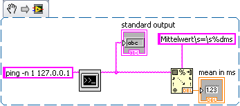
Also, I want to display the elapsed time for the connection (which varies due to fluctuations in the internet), performing actions such as continuously 'ping' the receiver from the server. Can someone show me the way to achieve this? Thank you very much.
Best regards
yukfai88
Please do not shout

How about using ping?
Insert the output in an analysis of string to read the value you need. Sorry my OS is in German so you have to adapt ;-)
-
Remote access share folder between two computers
I have two computers connected by a CAT5 cable, have all two firewall is enabled. This network has a server, DNS & DHCP server or router. Only two computers XP SP3.
- Firewall is enabled
- File sharing and printer checked with selected custom list
Two types of tests:
Test 1: I configured two computers with a static IP address and enter the IP subnet 10.0.0.0/24 network in the custom list. The PC - A (10.0.0.1) and typing\\computername or \\IP_AddressPC - B (10.0.0.2) access. Access to shared folder has no problem with this setting.
Test 2: I changed the dynamic IP address static IP on both computers and let XP itself generate dynamic IP 169.x.x.x. I went to the list of custom and changed in 169.0.0.0/16, this settings I'm unable to access the remote folder.
- I could not access by \\IP_Address get a message error "network path was not found.
- \\Computername took almost a minute to open a window, but he has now shared resources, such as file sharing.
- I can ping by IP address, but could not ping by ComputerName
Issues related to the:
- Class B is allowed in the custom list?
- Can I use the IP address dynamic Windows XP for the connection between two computers or on multiple computers?
- Why class C has worked very well and no class B?
- Is it because I used XP dynamic IP or custom list accesses no class B or both?
Johnny
Hello
Part of a Wireless cable/DSL Router is a DHCP server.
The server assigns the IP address to network computers are configured to Auto obtain IP address.
If for some reason, the computer cannot connect to the router, it cannot obtain an IP address and Windows assign a default IP 169.xxx.xxxx.xxx. This IP address is not functional for regular internet IP and network.
Since you don't have any DHCP server on your system, you must use static IP as you did before.Jack-MVP Windows Networking. WWW.EZLAN.NET
-
Hello. I am trying to solve a practical problem and I can't seem to deliver the VLAN. The presentation is as follows:
You have two two routers connected to each other. Each router has a switch and each switch has four related generic PC. Each PC on this switch belongs on its own VIRTUAL local network. Thus,.
Switch 1 Switch 2 - PC A - VLAN 10
- PC E - VLAN 10
- PC B - VLAN 20
- PC F - VLAN 20
- PC C - VLAN 30
- PC G - VLAN 30
- PC D - VLAN 40
- PC H - VLAN 40
So A PC on the router/switch 1 1 can ping ROUTER2/switch 2 E PC and it cannot ping all the others. So on and so forth.
So I tried to adjust the C VLAN 10 PC to check if the configuration of my work, and it does. But then I tie my router and sub interfaces, set the fa0/1 interface on my switch such as trunk and permit VLAN 10, 20, 30 and 40. Now, all PC on the router can ping each other! That should not happen. Now I don't know what the problem is. Can someone help me?
I have attached the docx and the tracer file package.
Sorry that I just realized you don't want connectivity between all computers.
Which is a relief, because watching your Setup, I didn't see why they wouldn't be able to :-)
You must use the ACLs on your subinterfaces to allow only the traffic you want.
If you want to allow any PC from any other PC on the same site to ping but only the PC in the same vlan on the other site, then use an outbound acl on the router serial interfaces.
If you only want to allow ping between the PC in the same vlan ACL use traffic entering on the subinterfaces.
Jon
-
Want to use internet to share WRV210 router between two LANs
Hello
I have the following scenario:
A LAN has access to internet via ADSL through a Fortigate 50B (192.168.100.0)
A new LAN (different segment) that should have access to the internet. (192.168.102.0)
Two local networks need to have shared access resources among themselves.
We have a WRV210 router between two LANs (192.168.100.0 WAN, 192.168.102.0 on LAN) configured in router mode.
Resources work very well, but internet does not work.
We receive answers internet addresses on 192.168.102.0 ping and tracert works very well, but we cannot navigate or connect to Skype, msn msg, etc..
We made on fortigate 50B routes this way:
192.168.102.0/255.255.255.0 192.168.100.102 internal
192.168.100.102 is an address WAN WRV210
We tried the gateway mode and internet works fine on 192.168.102.0, but 192.168.100.0 cannot contact 192.168.102.0 resources (obviously)
What can be wrong in case of ping and tracert works very well, but nothing else works?
Hi Willy,.
You need the WRV210 in not the router mode gateway mode.
Gateway mode active Stateful inspection, which will address translation from private to public IP addresses and NAT....
"But I think that the VLAN on the router segments members to talk to other members on the other vlan, so your comment.
Two local networks need to have shared access resources among themselves. "creates a problem.
.
A community previous publication says "with Port Based VLAN on the WRV210, there is no VLAN tagging and so on." It's more like say port 1 not to talk to port 2, because they are on separate physically designated VLAN (even if on the same subnet) and it is far as it goes. But with your configuration you want also to have the 2nd SSID do not talk to any wired client based on the RVS4000 as well? If so, this facility would not work because all wireless clients would be able to talk to cable customers and vice versa. But if you primary concern is simply to prevent the SSID 1 speaking with 2 SSID, it's doable in the page VLAN for the WRV210.
So if you want the WRV210 to allow switching between the VLAN port basis, it won't work the way it is set up now...
If you want to restrict access between IP hosts, I suggest using the list feature to access a managed switch that focuses on the PC or servers. A switch may be as a series of 200 or 300 small businesses switch, see URL below...
http://www.Cisco.com/en/us/products/ps10898/prod_models_comparison.html
But then allow all ports to be a member of the VLAN by default. I hope that I read your question correctly
Best regards, Dave
-
Routing between two remote sites connected over the VPN site to site
I have a problem ping between remote sites. Now the Cryptography and no nat ACL's for different sites just to affect traffic between the remote site and main site. I tried to add roads, adding other subnets to the crypto and no. ACL Nat at the remote sites... nothing worked. Any ideas?
Main site:
192.168.100.0 - call manager / phone VLAN
192.168.1.0/24 - data VLAN
Site 1:
192.168.70.0/24 - phone VLAN
192.168.4.0/24 - data VLAN
Site 2:
192.168.80.0/24 - phone VLAN
192.168.3.0/24 - data VLAN
Main router
Expand the IP ACL5 access list
10 permit ip 192.168.1.0 0.0.0.255 192.168.70.0 0.0.0.255
20 ip 192.168.1.0 allow 0.0.0.255 192.168.4.0 0.0.0.255
30 permits ip 192.168.100.0 0.0.0.255 192.168.4.0 0.0.0.255
IP 192.168.100.0 allow 40 0.0.0.255 192.168.70.0 0.0.0.255)
50 permit ip 10.255.255.0 0.0.0.255 192.168.70.0 0.0.0.255
Expand the IP ACL6 access list
10 permit ip 192.168.1.0 0.0.0.255 192.168.80.0 0.0.0.255
20 ip 192.168.1.0 allow 0.0.0.255 192.168.3.0 0.0.0.255
30 permits ip 192.168.100.0 0.0.0.255 192.168.3.0 0.0.0.255
IP 192.168.100.0 allow 40 0.0.0.255 192.168.80.0 0.0.0.255Expand the No. - NAT IP access list
10 deny ip 192.168.2.0 0.0.0.255 192.168.70.0 0.0.0.255
20 deny ip 192.168.200.0 0.0.0.255 192.168.4.0 0.0.0.255
30 deny ip 192.168.2.0 0.0.0.255 192.168.80.0 0.0.0.255
40 deny ip 192.168.200.0 0.0.0.255 192.168.3.0 0.0.0.255
320 ip 192.168.1.0 allow 0.0.0.255 any
IP 192.168.100.0 allow 330 0.0.0.255 anySite 1:
ACL5 extended IP access list
IP 192.168.70.0 allow 0.0.0.255 192.168.1.0 0.0.0.255
ip licensing 192.168.4.0 0.0.0.255 192.168.100.0 0.0.0.255
IP 192.168.70.0 allow 0.0.0.255 192.168.100.0 0.0.0.255
ip licensing 192.168.4.0 0.0.0.255 192.168.1.0 0.0.0.255
IP 192.168.70.0 allow 0.0.0.255 10.255.255.0 0.0.0.255
No. - NAT extended IP access list
deny ip 192.168.70.0 0.0.0.255 192.168.1.0 0.0.0.255
refuse the 192.168.4.0 ip 0.0.0.255 192.168.100.0 0.0.0.255
deny ip 192.168.70.0 0.0.0.255 192.168.100.0 0.0.0.255
refuse the 192.168.4.0 ip 0.0.0.255 192.168.1.0 0.0.0.255
deny ip 192.168.70.0 0.0.0.255 10.255.255.0 0.0.0.255
IP 192.168.70.0 allow 0.0.0.255 any
ip licensing 192.168.4.0 0.0.0.255 any
Site 2:
ACL6 extended IP access list
IP 192.168.80.0 allow 0.0.0.255 192.168.1.0 0.0.0.255
ip licensing 192.168.3.0 0.0.0.255 192.168.100.0 0.0.0.255
IP 192.168.80.0 allow 0.0.0.255 192.168.100.0 0.0.0.255
ip licensing 192.168.3.0 0.0.0.255 192.168.1.0 0.0.0.255
IP 192.168.80.0 allow 0.0.0.255 10.255.255.0 0.0.0.255
No. - NAT extended IP access list
deny ip 192.168.80.0 0.0.0.255 192.168.1.0 0.0.0.255
deny ip 192.168.3.0 0.0.0.255 192.168.100.0 0.0.0.255
deny ip 192.168.80.0 0.0.0.255 192.168.100.0 0.0.0.255
deny ip 192.168.3.0 0.0.0.255 192.168.1.0 0.0.0.255
deny ip 192.168.80.0 0.0.0.255 10.255.255.0 0.0.0.255
IP 192.168.80.0 allow 0.0.0.255 any
ip licensing 192.168.3.0 0.0.0.255 anyWhat should I do for these two sites can ping each other? I looked through the forums but can't seem to find someone with a similar problem, which has received a definitive answer.
Thanks in advance!
Hi, I assume that you need site 1 and 2 to communicate with each other via the main site right? If this is the case, then you need to set add the following lines to your ACL crypto:
Main router
Expand the IP ACL5 access list
IP 192.168.80.0 allow 0.0.0.255 192.168.70.0 0.0.0.255
IP 192.168.80.0 allow 0.0.0.255 192.168.4.0 0.0.0.255
ip licensing 192.168.3.0 0.0.0.255 192.168.70.0 0.0.0.255
ip licensing 192.168.3.0 0.0.0.255 192.168.4.0 0.0.0.255
Expand the IP ACL6 access list
IP 192.168.70.0 allow 0.0.0.255 192.168.80.0 0.0.0.255
IP 192.168.70.0 allow 0.0.0.255 192.168.3.0 0.0.0.255
ip licensing 192.168.4.0 0.0.0.255 192.168.3.0 0.0.0.255
ip licensing 192.168.4.0 0.0.0.255 192.168.80.0 0.0.0.255
Make sure you add these lines before the last permit
Expand the No. - NAT IP access list
deny ip 192.168.80.0 0.0.0.255 192.168.70.0 0.0.0.255
deny ip 192.168.80.0 0.0.0.255 192.168.4.0 0.0.0.255
deny ip 192.168.3.0 0.0.0.255 192.168.70.0 0.0.0.255
deny ip 192.168.3.0 0.0.0.255 192.168.4.0 0.0.0.255
deny ip 192.168.70.0 0.0.0.255 192.168.80.0 0.0.0.255
refuse the 192.168.4.0 ip 0.0.0.255 192.168.80.0 0.0.0.255
deny ip 192.168.70.0 0.0.0.255 192.168.3.0 0.0.0.255
refuse the 192.168.4.0 ip 0.0.0.255 192.168.3.0 0.0.0.255
Site 1:
ACL5 extended IP access list
IP 192.168.70.0 allow 0.0.0.255 192.168.80.0 0.0.0.255
ip licensing 192.168.4.0 0.0.0.255 192.168.80.0 0.0.0.255
IP 192.168.70.0 allow 0.0.0.255 192.168.3.0 0.0.0.255
ip licensing 192.168.4.0 0.0.0.255 192.168.3.0 0.0.0.255
Make sure that these lines are added before the last permit
No. - NAT extended IP access list
deny ip 192.168.70.0 0.0.0.255 192.168.80.0 0.0.0.255
refuse the 192.168.4.0 ip 0.0.0.255 192.168.80.0 0.0.0.255
deny ip 192.168.70.0 0.0.0.255 192.168.3.0 0.0.0.255
refuse the 192.168.4.0 ip 0.0.0.255 192.168.3.0 0.0.0.255
Site 2:
ACL6 extended IP access list
IP 192.168.80.0 allow 0.0.0.255 192.168.70.0 0.0.0.255
ip licensing 192.168.3.0 0.0.0.255 192.168.70.0 0.0.0.255
IP 192.168.80.0 allow 0.0.0.255 192.168.4.0 0.0.0.255
ip licensing 192.168.3.0 0.0.0.255 192.168.4.0 0.0.0.255
So make sure that these lines are added before the last permit
No. - NAT extended IP access list
deny ip 192.168.80.0 0.0.0.255 192.168.70.0 0.0.0.255
deny ip 192.168.3.0 0.0.0.255 192.168.70.0 0.0.0.255
deny ip 192.168.80.0 0.0.0.255 192.168.4.0 0.0.0.255
deny ip 192.168.3.0 0.0.0.255 192.168.4.0 0.0.0.255
So you're saying good enough your routers with these definitions which will be reached via one main remote sites (sites 1 and 2).
I would like to know if this is what you need.
-
cannot ping between remote vpn site?
vpn l2l site A, site B is extension vpn network, connect to the same vpn device 5510 to the central office and work well. I can ping from central office for two remote sites, but I cannot ping between these two vpn sites? Tried to debug icmp, I can see the icmp side did reach central office but then disappeared! do not send B next? Help, please...
permit same-security-traffic inter-interface
permit same-security-traffic intra-interface
!
object-group network SITE-a.
object-network 192.168.42.0 255.255.255.0
!
object-group network SITE-B
object-network 192.168.46.0 255.255.255.0
!
extended OUTSIDE allowed a whole icmp access list
HOLT-VPN-ACL extended access-list allow ip object-CBO-NET object group SITE-a.
!
destination SITE-a NAT (outside, outside) static source SITE - a static SITE to SITE-B-B
!
address for correspondence card crypto VPN-card 50 HOLT-VPN-ACL
card crypto VPN-card 50 peers set *. *.56.250
card crypto VPN-card 50 set transform-set AES-256-SHA ikev1
VPN-card interface card crypto outside
!
internal strategy group to DISTANCE-NETEXTENSION
Remote CONTROL-NETEXTENSION group policy attributes
value of DNS server *. *. *. *
VPN-idle-timeout no
Ikev1 VPN-tunnel-Protocol
Split-tunnel-policy tunnelspecified
Split-tunnel-network-list value REMOTE-NET2
value by default-field *.org
allow to NEM
!
remote access of type tunnel-group to DISTANCE-NETEXTENSION
Global DISTANCE-NETEXTENSION-attributes tunnel-group
authentication-server-group (inside) LOCAL
Group Policy - by default-remote CONTROL-NETEXTENSION
IPSec-attributes tunnel-group to DISTANCE-NETEXTENSION
IKEv1 pre-shared-key *.
tunnel-group *. *.56.250 type ipsec-l2l
tunnel-group *. *.56.250 ipsec-attributes
IKEv1 pre-shared-key *.
!!
ASA - 5510 # display route. include the 192.168.42
S 192.168.42.0 255.255.255.0 [1/0] via *. *. 80.1, outside
ASA - 5510 # display route. include the 192.168.46
S 192.168.46.0 255.255.255.0 [1/0] via *. *. 80.1, outside
ASA-5510.!
Username: Laporte-don't Index: 10
Assigned IP: 192.168.46.0 public IP address: *. *.65.201
Protocol: IKEv1 IPsecOverNatT
License: Another VPN
Encryption: 3DES hash: SHA1
TX Bytes: bytes 11667685 Rx: 1604235
Group Policy: Group remote CONTROL-NETEXTENSION Tunnel: remote CONTROL-NETEXTENSION
Opening time: 08:19:12 IS Thursday, February 12, 2015
Duration: 6 h: 53 m: 29 s
Inactivity: 0 h: 00 m: 00s
Result of the NAC: unknown
Map VLANS: VLAN n/a: no
!
ASA - 5510 # display l2l vpn-sessiondbSession type: LAN-to-LAN
Connection: *. *.56.250
Index: 6 IP Addr: *. *.56.250
Protocol: IPsec IKEv1
Encryption: AES256 3DES hash: SHA1
TX Bytes: bytes 2931026707 Rx: 256715895
Connect time: 02:00:41 GMT Thursday, February 12, 2015
Duration: 13: 00: 10:00Hi Rico,
You need dynamic nat (for available IP addresses) for the two side to every subset of remote access to the other side remote subnet and so they can access every other subnet as if both from the traffic from your central location.
example:
Say, this IP (10.10.10.254) is unused IP to the central office, allowed to access remote tunnel 'A' and 'B' of the site.
object-group network SITE-a.
object-network 192.168.42.0 255.255.255.0
!
object-group network SITE-B
object-network 192.168.46.0 255.255.255.0dynamic source destination SITE-a. 10.10.10.254 NAT (outdoors, outdoor)
public static SITE SITE-B-Bdestination NAT (outdoors, outdoor) SITE-B 10.10.10.254 dynamic source
SITE static-SITE aHope this helps
Thank you
Rizwan James
-
Cannot connect call between two SX20
Hello world
I've implemented two Cisco SX20 units at two sites. When you attempt to place the call between two units, it is unstable. In particular, sometimes the call is connected, sometimes, it is not connected even if ping, tracert are Ok. It's very strange. I'm sure that the SX20 unit works well. If I make a conclusion that there is a problem with my network but I don't exactly know why.
All the world is facing this problem before?
Dzung.
Hey yours,
Disable NAT if you do not use.
Also useful to configure QoS, check on your link packet loss and bandwidth.
-
Is - a used the 3602e as a bridgeing only between two networks?
Is - a used the 3602e as a bridgeing only between two networks? 2504 controller version 7.4.100 I can't ping anything on one side or the other of the network, but I can ping from each access point controller. I have two 1552 setup the same way with no problems. Anyone seen this before?
Thank you!
In the case of 3602e as bridge link and you bet the config is a working one, then I would check the antennas if they are properly aligned, if you use a higher gain, a good one would be a necessary in the case of 3602e, I think that Yes.
-
How backup VPN configuration between two universities?
Hello, I am a student of the Greece and I have a graduation project to configure Backup VPN between two universities. Principal of communication made with leased lines. I study a lot, but now that it's time for implementation I have some thoughts:
-What hardware and software IOS do I need? Cisco 1841 it is ok for A & D routers?
-Use GRE IPSec transport mode or IPsec Tunnel mode?
-What will be the failover mechanism for switching traffic lines leased to IP VPN Backup and opposite? A teacher told me something about the Interface Prioritys. I read somewhere that this is done with the such as EIGRP routing protocol. who was right the Professor or the book? :-D
-In the same place, they have Firewall and NAT, I need to do any action for this?
The attached file contains topology I want to implement
'My' talk site 1
2 a Central Site
E communicates with A, but no traffic is to A of E with normal circumstances. Subnet on E access Internet through F, then press D. VPN will be implemented on the LAN but the specific source E traffic will pass through the Backdoor VPN (I think that the solution to this is ACL on the router). They have no routing protocol in 'my' site A directly connected routers and the default routes.
How imlement this?
I think the first thing to do is A to D connectivity
I will try to do this to tracers package first, but how can ' I imitate the SP network?
I need help I can get!
Hi John,.
In our scenario, given that our main connection is a direct leased line between E and F, so I guess there is no other network between the two routers. In this case we do not need to configure SLA monitoring or any interface a priority. We can simply enter two default routes:
IP route
IP route 254
In this scenario, if the leased line interface goes down, the second default route is used and the traffic should be routed by A router.
SLA monitoring monitors connection (using the ping tests) by one of the interfaces of the router, and when we are not able to ping from one server (specified in the configuration of the SLA) through the interface, then we change the default track to track traffic through some other interface.
So, in your scenario, we can monitor the connection between E and F, and when the link goes down, we can change the default route to point a.
This is useful in the scenario where we have another ISP connection as our primary connection.
Here is a link on how to configure SLA monitoring on the router:
http://www.Cisco.com/en/us/docs/iOS/12_4/ip_sla/configuration/guide/hsicmp.html
After you have configured the SLA followed by using the link above, you can bind it to the default route by using the following command line:
track road IP / / default main route
IP route 255 / / default route with a metric of higer that comes into play when the main default route goes down
In addition, the sample configuration that you give in the doc is almost correct, defined transformation is missing just a hashing algorithm. Here is a link with an example for a tunnel from lan-to-lan between two routers:
-
IPsec VPN between two routers - mode ESP Transport and Tunnel mode
Hi experts,
I have this question about the Transport mode and Tunnel mode for awhile.
Based on my understanding of 'Transport' mode is not possible because you always original "internal" private in the IP headers or IP addresses. They are always different as public IP on interfaces enabled with Crypto Card addresses. When encapsulated in the VPN tunnel, the internal IP addresses must be included or the remote VPN router won't know where to forward the packet.
To test, I built a simple GNS3 with three routers laboratory. R1 and R3 are configured as VPN routers and the R2 must simulate Internet.
My configs are also very basic. The R2 is routing between 1.1.1.0/24 and 2.2.2.0/24. It is defined as the gateway of R1 and R3.
R1:
crypto ISAKMP policy 100
BA aes
preshared authentication
Group 2
ISAKMP crypto key 123456 address 2.2.2.2
!
Crypto ipsec transform-set ESP_null null esp esp-sha-hmac
!
10 map ipsec-isakmp crypto map
defined peer 2.2.2.2
transformation-ESP_null game
match address VPN!
list of IP - VPN access scope
ip permit 192.168.1.0 0.0.0.255 10.0.0.0 0.0.0.255
!R3:
crypto ISAKMP policy 100
BA aes
preshared authentication
Group 2
ISAKMP crypto key 123456 address 1.1.1.2
!
!
Crypto ipsec transform-set ESP_null null esp esp-sha-hmac
!
10 map ipsec-isakmp crypto map
defined peer 1.1.1.2
transformation-ESP_null game
match address VPN!
list of IP - VPN access scope
Licensing ip 10.0.0.0 0.0.0.255 192.168.1.0 0.0.0.255I configured transform-"null" value, while it will not encrypt the traffic.
Then I tried the two 'transport' mode and mode "tunnel". I ping a host in the internal network of the R1 to another host in the internal network of the R3. I also tried 'telnet'. I also captured packets and carefully compared in both modes.
Packets encapsulated in exactly the same way!
It's just SPI + sequence No. +
+ padding I will attach my screenshots here for you guys to analyze it. I would be grateful for any explanation. I confused maybe just when it comes to the NAT...
I guess my next step is to check if the two modes to make the difference when the GRE is used.
Thank you
Difan
Hi Difan,
As you point out the mode of transport is not always applicable (i.e. applicable if IP source and destination is equal to corresnpoding proxy IDs).
A typical scenario in this mode of transport is used:
-Encryption between two hosts
-GRE tunnels
-L2TP over IPsec
Even if you set "transport mode" this does not mean that it will be used. IOS routers and I blieve also ASA will perform backup even if the mode of transport is configured but does not apply in tunnel mode.
I can take a look at your traces to sniff, but all first can you please check if you transport mode on your ipsec security associations? "See the crypto ipsec his" exit you will show the tunnel or transport mode.
HTH,
Marcin
-
L2l VPN between two ASA5505 works not
Let me start who I know a thing or two about networks. VPN not so much.
I am trying to configure a Site-toSite VPN between two ASA 5505. I am building this in a laboratory of the Office before I deploy it to the end sites. I are the indications on this very informative forum and think I have it set up correctly. I can see the tunnel is being built and I see same incrementation of the traffic counters. But the real user sessions do not seem to work. For example, ping and telnet does not work.
An excerpt from the syslog for a ping test on a computer on the remote end.
(10.1.10.5 is the local computer, 10.1.11.5 is the remote computer. 10.1.11.1 is the interface of the ASA remote interior)
6. January 20, 2012 | 01:04:12 | 302021 | 10.1.11.1 | 0 | 10.1.10.5 | 1. Connection of disassembly for faddr gaddr laddr 10.1.10.5/1 10.1.10.5/1 10.1.11.1/0 ICMP
6. January 20, 2012 | 01:04:10 | 302020 | 10.1.10.5 | 1. 10.1.11.1 | 0 | Built of outbound ICMP connection for faddr gaddr laddr 10.1.10.5/1 10.1.10.5/1 10.1.11.1/0
6. January 20, 2012 | 01:04:07 | 302021 | 10.1.11.1 | 0 | 10.1.10.5 | 1. Connection of disassembly for faddr gaddr laddr 10.1.10.5/1 10.1.10.5/1 10.1.11.1/0 ICMP
6. January 20, 2012 | 01:04:05 | 302020 | 10.1.10.5 | 1. 10.1.11.1 | 0 | Built of outbound ICMP connection for faddr gaddr laddr 10.1.10.5/1 10.1.10.5/1 10.1.11.1/0
6. January 20, 2012 | 01:04:02 | 302021 | 10.1.11.1 | 0 | 10.1.10.5 | 1. Connection of disassembly for faddr gaddr laddr 10.1.10.5/1 10.1.10.5/1 10.1.11.1/0 ICMP
6. January 20, 2012 | 01:04:00 | 302020 | 10.1.10.5 | 1. 10.1.11.1 | 0 | Built of outbound ICMP connection for faddr gaddr laddr 10.1.10.5/1 10.1.10.5/1 10.1.11.1/0
6. January 20, 2012 | 01:03:57 | 302021 | 10.1.11.1 | 0 | 10.1.10.5 | 1. Connection of disassembly for faddr gaddr laddr 10.1.10.5/1 10.1.10.5/1 10.1.11.1/0 ICMP
6. January 20, 2012 | 01:03:55 | 302020 | 10.1.10.5 | 1. 10.1.11.1 | 0 | Built of outbound ICMP connection for faddr gaddr laddr 10.1.10.5/1 10.1.10.5/1 10.1.11.1/0
6. January 20, 2012 | 01:03:48 | 302021 | 10.1.11.5 | 0 | 10.1.10.5 | 1. Connection of disassembly for faddr gaddr laddr 10.1.10.5/1 10.1.10.5/1 10.1.11.5/0 ICMP
6. January 20, 2012 | 01:03:46 | 302020 | 10.1.10.5 | 1. 10.1.11.5 | 0 | Built of outbound ICMP connection for faddr gaddr laddr 10.1.10.5/1 10.1.10.5/1 10.1.11.5/0
6. January 20, 2012 | 01:03:43 | 302021 | 10.1.11.5 | 0 | 10.1.10.5 | 1. Connection of disassembly for faddr gaddr laddr 10.1.10.5/1 10.1.10.5/1 10.1.11.5/0 ICMP
6. January 20, 2012 | 01:03:41 | 302020 | 10.1.10.5 | 1. 10.1.11.5 | 0 | Built of outbound ICMP connection for faddr gaddr laddr 10.1.10.5/1 10.1.10.5/1 10.1.11.5/0
6. January 20, 2012 | 01:03:38 | 302021 | 10.1.11.5 | 0 | 10.1.10.5 | 1. Connection of disassembly for faddr gaddr laddr 10.1.10.5/1 10.1.10.5/1 10.1.11.5/0 ICMP
6. January 20, 2012 | 01:03:36 | 302020 | 10.1.10.5 | 1. 10.1.11.5 | 0 | Built of outbound ICMP connection for faddr gaddr laddr 10.1.10.5/1 10.1.10.5/1 10.1.11.5/0
5. January 20, 2012 | 01:03:32 | 713041 | IP = 192.168.24.211, initiator of IKE: New Phase 1, Intf inside, IKE Peer 192.168.24.211 address local proxy 10.1.10.0, address remote Proxy 10.1.11.0, Card Crypto (outside_map)This is the configuration for one of them. The other is configured in the same way with the usual across settings.
ASA Version 8.2 (1)
!
hostname ASATWDS
!names of
name 10.1.11.0 remote control-network
!
interface Vlan1
nameif inside
security-level 100
IP 10.1.10.1 255.255.255.0
!
interface Vlan2
nameif outside
security-level 0
IP 192.168.24.210 255.255.255.0
!
interface Ethernet0/0
switchport access vlan 2
!
interface Ethernet0/1
!
interface Ethernet0/2
!
interface Ethernet0/3
!
interface Ethernet0/4
!
interface Ethernet0/5
!
interface Ethernet0/6
!
interface Ethernet0/7
!
passive FTP mode
access extensive list ip 10.1.10.0 outside_1_cryptomap allow 255.255.255.0 255.255.255.0 network-remote control
access extensive list ip 10.1.10.0 inside_nat0_outbound allow 255.255.255.0 255.255.255.0 network-remote control
pager lines 24
Enable logging
asdm of logging of information
Within 1500 MTU
Outside 1500 MTU
ICMP unreachable rate-limit 1 burst-size 1
don't allow no asdm history
ARP timeout 14400
Global 1 interface (outside)
NAT (inside) 0-list of access inside_nat0_outbound
NAT (inside) 1 0.0.0.0 0.0.0.0
Route outside 0.0.0.0 0.0.0.0 192.168.24.1 1
course outside remote control-network 255.255.255.0 192.168.24.1 1
Timeout xlate 03:00
Timeout conn 01:00 half-closed 0:10:00 udp 0:02:00 icmp 0:00:02
Sunrpc timeout 0:10:00 h323 0:05:00 h225 mgcp from 01:00 0:05:00 mgcp-pat 0:05:00
Sip timeout 0:30:00 sip_media 0:02:00 prompt Protocol sip-0: 03:00 sip - disconnect 0:02:00
Timeout sip-provisional-media 0:02:00 uauth 0:05:00 absolute
timeout tcp-proxy-reassembly 0:01:00
dynamic-access-policy-registration DfltAccessPolicy
Enable http server
http 10.1.10.0 255.255.255.0 inside
No snmp server location
No snmp Server contact
Server enable SNMP traps snmp authentication linkup, linkdown cold start
Crypto ipsec transform-set esp-SHA-ESP-3DES-3des esp-sha-hmac
life crypto ipsec security association seconds 28800
Crypto ipsec kilobytes of life - safety 4608000 association
card crypto outside_map 1 match address outside_1_cryptomap
card crypto outside_map 1 set pfs
peer set card crypto outside_map 1 192.168.24.211
card crypto outside_map 1 set of transformation-ESP-3DES-SHA
card crypto outside_map 1 phase 1-mode of aggressive setting
card crypto outside_map 1 the value reverse-road
outside_map interface card crypto outside
crypto ISAKMP allow outside
crypto ISAKMP policy 10
preshared authentication
3des encryption
sha hash
Group 2
life 86400
Telnet timeout 5
SSH timeout 5
Console timeout 0
dhcpd outside auto_config
!
dhcpd address 10.1.10.5 - 10.1.10.36 inside
dhcpd dns 209.18.47.61 209.18.47.62 interface inside
dhcpd allow inside
!a basic threat threat detection
Statistics-list of access threat detection
no statistical threat detection tcp-interception
WebVPN
tunnel-group 192.168.24.211 type ipsec-l2l
IPSec-attributes tunnel-group 192.168.24.211
pre-shared-key *.
!
class-map inspection_default
match default-inspection-traffic
!
!
type of policy-card inspect dns preset_dns_map
parameters
message-length maximum 512
Policy-map global_policy
class inspection_default
inspect the preset_dns_map dns
inspect the ftp
inspect h323 h225
inspect the h323 ras
inspect the rsh
inspect the rtsp
inspect esmtp
inspect sqlnet
inspect the skinny
inspect sunrpc
inspect xdmcp
inspect the sip
inspect the netbios
inspect the tftp
inspect the icmp
!
global service-policy global_policy
context of prompt hostname
Cryptochecksum:b4bea5393489da3aa83f281d3107a32eThe Configuration looks good to me, but I think that you don't need next: -.
card crypto outside_map 1 phase 1-mode of aggressive setting
card crypto outside_map 1 the value reverse-road
Anyway,.
1 > can you please check if the computer you are trying to Ping or Telnet isn't the Machine based Firewall or anti-virus or iptables (Linux)?
2 > dough out of the
a > sh crypto ipsec his
b > sh crypto isakmp his
Manish
-
Traffic is failed on plain IPSec tunnel between two 892 s
Have a weird case and you are looking for some suggestions/thougs where to dig because I have exhausted the options.
Note: I replaced the Networkid real to a mentined below.
Topology: a classic IPSec VPN tunnel between two 892 s of Cisco, with pre-shared key and no GRE. A 892 (branch_892) has access to the Internet using PPPoE and has three network / VLAN behind it. A VLAN is coordinated to the PPPoE internet access. Access to the other two VLAN - VL92 (100.100.200.0/24) and VL93 (100.100.100.0/24) is performed via the VPN tunnel.
Second 892 (892_DC) has just one interface - WAN on Gigabit enabled/connected and a static route to the default GW. It doesn't have any defined interal network. If the router is strictly used to send traffic to VL92/VL93 to the domestic 892 via IPSec tunnel.
Here's the problem: access to VL93 (100.100.100.0/24) works, however for VL92 (100.100.100.0/24) - does not work.
Devices in VL92 I ping IP address of 892_DC through the VPN tunnel. The 892_DC router I can ping devices in VL92. However, I can't VL92 ping any device beyond the 892_DC and at the same time the packets arriving on 892_DC for VL92 are not sent through the VPN tunnel.
I took the package trace on 892_DC using capture point/buffer to nathalie caron to VL92 packages and saw that the traffic coming to the 892_DC. I run the nathalie caron even on Branch_892, and there was not a single package.
So... What's the problem? More interesting, I modified the way left on VL92 access list and still - no packets are sent through the tunnel.
Any idea? Two routers config are below
-------
892_DC #show ru
!
crypto ISAKMP policy 10
BA aes 256
hash sha256
preshared authentication
Group 2
isakmp encryption key * address 1.2.3.4
ISAKMP crypto keepalive 10 periodicals
!
address of 1.2.3.4 crypto isakmp peers
Description of-COIL-892
!
!
Crypto ipsec transform-set IT-IPSec-Transform-Set esp - aes 256 sha256-esp-hmac
Crypto ipsec df - bit clear
!
map IT ipsec - IPSec crypto - Crypto - map 10-isakmp
defined peer 1.2.3.4
disable the kilobytes of life together - the security association
86400 seconds, life of security association set
the transform-set IT-IPSec-Transform-Set value
match a lists 101
market arriere-route
QoS before filing
!
interface GigabitEthernet0
IP 10,20,30,40 255.255.255.240
IP 1400 MTU
IP tcp adjust-mss 1360
automatic duplex
automatic speed
card crypto IT-IPSec-Crypto-map
!
IP route 0.0.0.0 0.0.0.0 10.20.30.41
!
access list 101 ip allow any 100.100.100.0 0.0.0.255 connect
access list 101 ip allow any 100.100.200.0 0.0.0.255 connect
-------------------------------------------------------------------------------------
Branch_892 #sh run
!
crypto ISAKMP policy 10
BA aes 256
hash sha256
preshared authentication
Group 2
isakmp encryption key * address 10,20,30,40
ISAKMP crypto keepalive 10 periodicals
!
address peer isakmp crypto 10,20,30,40
!
!
Crypto ipsec transform-set IT-IPSec-Transform-Set esp - aes 256 sha256-esp-hmac
Crypto ipsec df - bit clear
!
map IT ipsec - IPSec crypto - Crypto - map 10-isakmp
defined peer 10,20,30,40
disable the kilobytes of life together - the security association
86400 seconds, life of security association set
the transform-set IT-IPSec-Transform-Set value
match address 101
market arriere-route
QoS before filing
!
FastEthernet6 interface
Description VL92
switchport access vlan 92
!
interface FastEthernet7
Description VL93
switchport access vlan 93
!
interface GigabitEthernet0
Description # to WAN #.
no ip address
automatic duplex
automatic speed
PPPoE-client dial-pool-number 1
!
interface Vlan1
Description # local to #.
IP 192.168.1.254 255.255.255.0
IP nat inside
IP virtual-reassembly in
!
interface Vlan92
Description fa6-nexus e100/0/40
IP 100.100.200.1 255.255.255.0
!
interface Vlan93
Description fa7-nexus e100/0/38
IP 100.100.100.1 255.255.255.0
!
interface Dialer0
no ip address
No cdp enable
!
interface Dialer1
IP 1.2.3.4 255.255.255.248
IP mtu 1454
NAT outside IP
IP virtual-reassembly in max-pumping 256
encapsulation ppp
IP tcp adjust-mss 1414
Dialer pool 1
Dialer-Group 1
Authentication callin PPP chap Protocol
PPP chap hostname ~ ~ ~
PPP chap password =.
No cdp enable
card crypto IT-IPSec-Crypto-map
!
Dialer-list 1 ip protocol allow
!
access-list 101 permit ip 100.100.100.0 0.0.0.255 any
access-list 101 permit ip 100.100.200.0 0.0.0.255 any
!
IP route 0.0.0.0 0.0.0.0 Dialer1
Yes correct sounds - so another possible problem is the routing is routing 100% correct on both sides? Can you put the two sides config for review?
Maybe you are looking for
-
VAIO 13 Pro won't turn on without plug
Since I started to install the new updates, which never completely installed through vaio updates. They would fail to install. Since then, my laptop lights not connected.Don't load increased from 77 per cent and if I unplug the power, the laptop auto
-
Satellite L450D - nothing else happens after the BIOS update
Toshiba Bulletin Board recommended 1 new message. Downloaded updated BIOS available. Frozen computer during the update and what would not be it. Now, the computer is totally dead. Power light turns on when the connected external CAP but nothing else.
-
Pavilion 231014: need help from ERD com.
We must use the repair disk to see if it will be useful. The computer is current on and has different problems. The info on the drive says press any key to start the computer from the system repair disc if you are prompted. If the computer is not
-
Programmatically create new consumers in a MANUAL
Howdy, I am struggling with a concept for an installation of BAU. Say I have a main VI consisting of one producer and single consumer sharing a queue, which can be filled in entries/actions of the main front of the VI. Convening of reentrant under
-
Hello, I would like to know if I can replace my CPU in my laptop. I have a laptop HP 15-r007tx .