single-board rio Guide
I bought a Single-Board RIO 9636. It is not a trial edition, and I don't know how to program the single board rio. Where can I find the user for sbrio guide? This is my first time to use sbrio.
Hey Percy,
The user manual and specifications for the sbRIO-9636 are linked from the tab "resources" in the template page sbRIO-9636 on ni.com.
About the getting started with your new system, I recommend that you follow the guidelines here: http://www.ni.com/gettingstarted/
This tutorial is a directive "choose your adventure. When he asks you what hardware you use, follow the path for CompactRIO systems, which is a packaged version of the NI Single-Board Rio.
See you soon,.
Tags: NI Hardware
Similar Questions
-
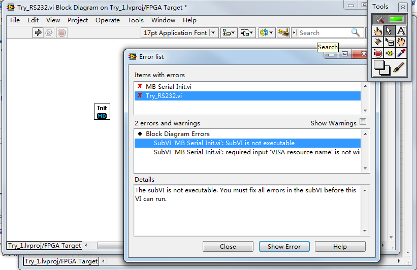
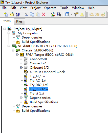
I want to apply the library modbus (http://sine.ni.com/devzone/cda/epd/p/id/4756) on the single-board rio sbRIO-9636 for serial RS232 communication. And what is the procedure in detail for this application?
I copy the files "NI Modbus.llb" and "nimodbus.mnu" under the D:\Program NIUninstaller Instruments\LabVIEW 2012\user.lib.
But when I add the module "Init.vi MB" in vi for FPGA, it shows that it is not executable.
If I'm wrong, but I don't think that the Modbus Library is supported on the sbRIO.
-
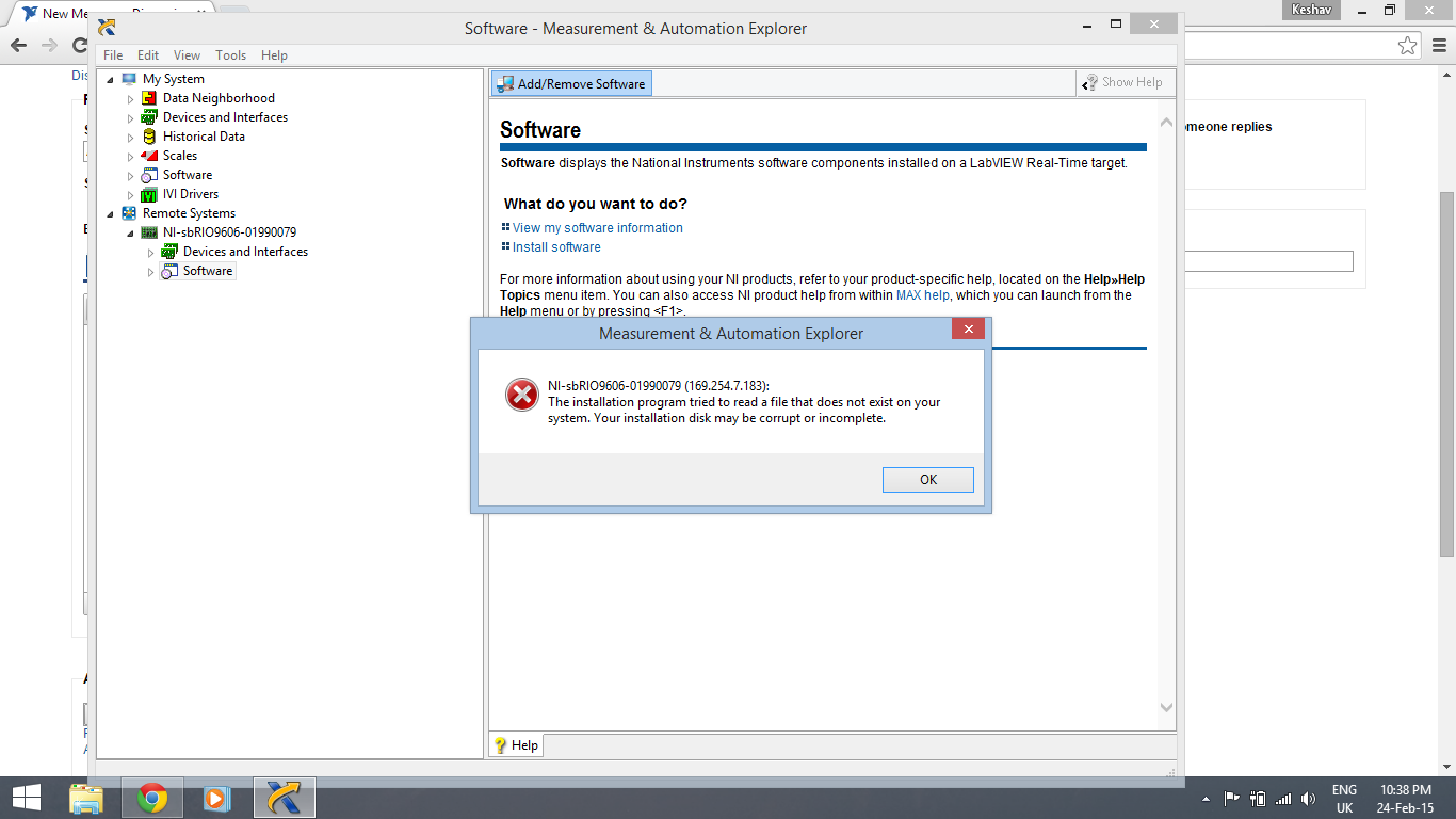
Add software to Single Board Rio NI Max
Hello
I am trying to install the software required for Sb rio using 9606 or MAX.
However, this message is to be invited:I would appreciate if you guys can be of any help.
Thank you
Kind regards
KeshavThe error you get generally occurs only if you have something installed on your target that is not available from your host. If you feel that you have everything you need already on your host the safest to do thing is probably to format the target of MAX and then proceed to install what you need.
-
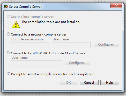
Hello, I have deployed the vi successfully, but when I click on the button "run" in the vi, the following diagram appeared, I wonder what is the compiler and where I could find it?
My only advice rio is sbRIO-9636.
And Labview 2012 edition in English
I installed the 2012 Eng real-time, FPGA 2012 Eng and rio 9636 the disk driver.
The system is 32-bit win7.
Thank you.
Hi percy.
I think you are missing the FPGA Xilinx tools:
http://Joule.NI.com/nidu/CDs/view/p/ID/3209/lang/en
More information can be found here:
Compilation of Xilinx tools I have to compile my Code FPGA?
http://digital.NI.com/public.nsf/allkb/A4B20D58C051DFB386257A56007BB0B2 -
sbRIO-9651 IO corresponding length
We plan to interface high speed ADC (1gech/s x8bit) that uses a wide interface LVDS (two samples) from 16-bit to a sbRIO-9651. Is there a resource that provides information about the sbRIO-9651 module layout details as worst case length offset series in differential pairs and between differential pairs that exist on the module (independent of our own layout of the Board of Directors)?
Since the interface use a common differential clock and wide 16-bit interface, I'm trying to get a sense tilt the worst case there might be between pairs differential seperatate.
I can they use sheet date architecting to get an idea of the maximum transfer rate, but are there restrictions on the module itself that will limit rates date?
Hi abadobid,
The SbRIO-9651 manual specifications (table 8) should have the details of length sur-module trace info you are looking for.
In addition, I recommend reading the Design Guide for the SOM carrier for detailed techniques, guidelines and requirements for the design of carrier card.
Finally, for future issues are the design of specific equipment for the SOM, we have implemented a dedicated community/forum that will probably be the best place to get help.
Community of developers of hardware for NI Single-Board RIO and module system
Resources for the system OR on the Module
Kind regards
-
I have a sbRIO 9602. He worked well with an executable running when it lights up. Now, the system is not responding. I can't reach it to the static IP address, that he had. The status light does not come on when it is running (no POST?). I tried to reset the IP address but MAX is not discovered it. The console out seems to be not working either. I can try, or should it be sent in for repair?
Hi Skryger,
If the Self Test (POST) does not occur, as evidenced by the lack of light when turned on the status light, then the jury you have is probably damaged and will need to be repaired.
If you want to troubleshoot more yourself, I would first check the supply voltage that you apply to the Single-Board RIO input terminals is not reversed and is between 19-30VDC with a multimeter. If you can check that you apply voltage to the input terminals but the Single-Board RIO still don't POST, while it is damaged.
If you want to dig a little deeper, you might probe both terminals of F2, the fuse input power (it's in the corner of the nearest the power connector card), with a measure of resistance or continuity AFTER you make sure that you unplug the Single-Board RIO of all power. If the fuse is high impedance or open, so very probably something accidentally shorted connections on the circuit board causing a surge of current, blowing the fuse (2Amps, not replaceable, the sbRIO-9602 User Guide).
Another possibility for the damage is documented in the User Guide on page 11. If Single - Board RIO is used as a constant in a system point and more of 3Amps of current through its plan to return to power, constituent of protection will be fuse opened. You need to check the external devices that share the power used for Single - Board RIO have their own lanes dedicated to the power supply ground.
You can contact OR for a return authorization of hardware (RMA) to www.ni.com/support (here is a step by step checklist for info to be ready when you call). After contacting the support, they can help you solve what may have spent in Single-Board RIO and determine if the Single-Board RIO is under warrantly also.
Kind regards
-
meter in the sbrio limitations
I received conflicting information on the width minimum counter on a sbrio pusle.
The documentation specifies a minimum 100 ns pulse still dig it can be done at 40 MHz.
Why is it not possible to count impulses pretty accuratly using a loop of an individual program timed to 25ns impulses which are separated at least 25 ns.
I do not have 100% of all counted impulses but need to get the best of them.
What is the cause for the limitations, I haven't read any of the sctl?
Hi all
Another emphasis of the number 10 MHz is that it represents what can be accomplished with a common wiring for Single - Board RIO and using 5V signaling rates and operates all 110 DIO lines at the same time (worst case scenario). The user guide for Single-Board RIO gives a schematic representation of the circuits between the DIO and FPGA pins and discusses the characteristic impedance of the traces on the map (60 ohms). Given this knowledge, you can see the part number of the switch bus single board onboard, which further investigation part shows will ensure only 5V to 3.3V translation at speeds of up to 10 MHz. If the external signaling levels are 3, 3V native FPGA, the throttling of the bus switch would become less of a problem. Given a combination of good matching impedance of the trace to the impedance of the cable (use the cable recommended in the user guide), 3.3V report levels and carefully select what DIO lines operate simultaneously, you can get bandwidth signals significatly higher for the FPGA with signal integrity is good. Come on, I dare a range of 30 to 35 MHz consistantly.
The bandwidth of traces connections between the fitting and FPGA is a different specification for sampling frequency. It is true, as fast as you can get the a VI LabVIEW FPGA to compile reliable, enjoy the signal in LabVIEW FPGA (60 or 80 MHz for example). Fastest sampling will give you the best temporal resolution when the edges occur, but does not mean that you can communicate reliably via a digital Protocol to 80 MHz. Traces will always limit to how signals are transmitted to and from the FPGA.
Hope this clears things up,
-
Problem with analog inputs on sbrio 9627
Hey guys!
I have a problem in my Single Board RIO 9627.
I use 4 differential analog inputs (AI0, AI1, AI2 and AI3).
What happens is that when I place a sensor or even a button on one of the entries and nothing on the other inputs, it affects all other inputs, increase in the level of each input voltage.
Can someone tell me how to solve this problem in the hardware or software?Thank you!
Multiplexed inputs must have a low impedance! If you have pictures of ghosts.
Attach entries open to GND (or do not read
 )
)If you want to read switches or buttons use a pull upwards or downwards the resistance.
-
Restrict the LabVIEW deployment on NOR sbRIO
Hi all
I searched a lot to find a solution, but could not find one.
I have to protect my controller sbRIO OR deploy any application of LV
For example, if anyone with LV connects to the network of the controller, it should be not able to deploy anything to sbRIO before filling the credentials of the controller.Web configuration of the controller, I deleted all permissions to "everyone" group and set password for the user "admin".
After that, MAX OR requires a password before you save anything to the controller, but LV does not require anything before you proceed with the connection of the programmer and the deployment of a VI on it.Could you please help me?
Thank you in advance.
Khoren
What Single-Board RIO device do you use (Linux or VxWorks RTOS based?)
The following white paper explains how to protect a Single-Board RIO and CompactRIO against unauthorized access.
Overview of best practices for safety in RIO systems
http://www.NI.com/white-paper/13069/en/
Looks like you need configure access to the server VI in part 1 to read the Security white paper.
Kind regards
-
specifications of clock sbRIO-9651 SoM FPGA fabric.
Hello
I would like to know the following specifications about the clock (clock of fabric) FPGA of the NOR sbRIO-9651 SoM:
-Precision (ppm)
-Aging (ppm/year)
-Temperature (ppm / ° C)
-Skew (ppm)I couldn't find anything related to this in the specification document.
Is it possible to use an external clock to repalce this one if the specification does not meet our requirement? This clock would be managed by a Board of business custom.
Thank you
Michel
Michel,
The accuracy of the clock is ±50 ppm. You can use an external clock as a source for single-cycle timed loops. The first logical level - things outside SCTLs - is still controlled by the internal oscillator at 50 ppm, but logically or e/s who needs a different precision can be placed in a SCTL and use the external clock. There is some good information on how to import a clock on our developer community material for NI Single-Board RIO and module system. Remember that the quantity of resources used and their frequency toggle will have an impact on the overall jitter of your system.
Thank you
Bryan
-
I have a cRIO-9075 serving piece of alternative/backup for one of our production test systems. I was about to try a new code on this backup, but I can't connect to it. I searched in MAX and tried to ping to the IP address that it should be, but I get no response. It has been configured with a static IP address so it would be ready to be deployed if necessary.
Is there anyway that I can get back to the default IP address so I can connect to it?
Take a look at page 17 of the user of 9075 Manual: http://www.ni.com/pdf/manuals/375650b.pdf
To reset the IP address of the 9075 you will need to walk through the following steps:
1 press and hold to reset for 5 seconds, then release. The status light
comes on, then starts to blink three times every few seconds. The
chassis is now in safe mode with the release of the compatible serial port.
You can use a serial port terminal to read the IP address of the
controller. If you want the controller to a new DHCP protocol
connection, go to step 2.2 press and hold to reset for 5 seconds, then release. The status light
Repeat the same behavior. The cRIO-9075/9076 trying to establish
a new connection to DHCP. If he fails, he attributes to a link-local
IP address. If the DHCP connection is effective and appropriate for
your application, go to step 4.3. configure the IP address and other network settings in MAX.
4. press and release the Reset button to restart the chassis.
The following documents will also be useful.
Why don't my CompactRIO or Single-Board RIO controller is displayed in Measurement & Automation Explorer (MAX)? - http://digital.ni.com/public.nsf/allkb/ABE4BC247E8AC9BC8625734E005CAB42?OpenDocument
Connection to a target LabVIEW Real - Time (RT) directly with a cable crossed - http://digital.ni.com/public.nsf/allkb/72AE8CADA1AF075686256A16005D55B1
-
Hi all
I'm under LabView 2013 and have updated all drivers and versions on my local computer and also on the Single Board RIO 9636 I use. My goal is to measure 4 similar entries corresponding to four different microphones and then each individual signal as an output wave form. I try this using the FIFO DMA 4.
The problem that I am running is that I am not able to read data from the RT Microprocesssor VI using the FIFO 4. Reading methods. I'm relatively new to using a FPGA and labVIEW programming. I attach two diagrams for information purposes. I thank in advance for any help, you may be able to provide.
mcoe12 wrote:
What happens is that data from the FIFO are just 1 and the real are not the case of the incoming data.
AH! If you said that in the first place, I have identified the problem in the first post. It seems that your data types do not match - fixed point for the FIFO DMA configuration does not match data from the analog input. That's what the small red "points of coercion" you are showing on writing of FIFO. My guess is that's why data is not properly through.
While you edit digital representations, also change the sampling frequency is an integer, to match the input of the timer.
-
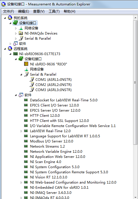
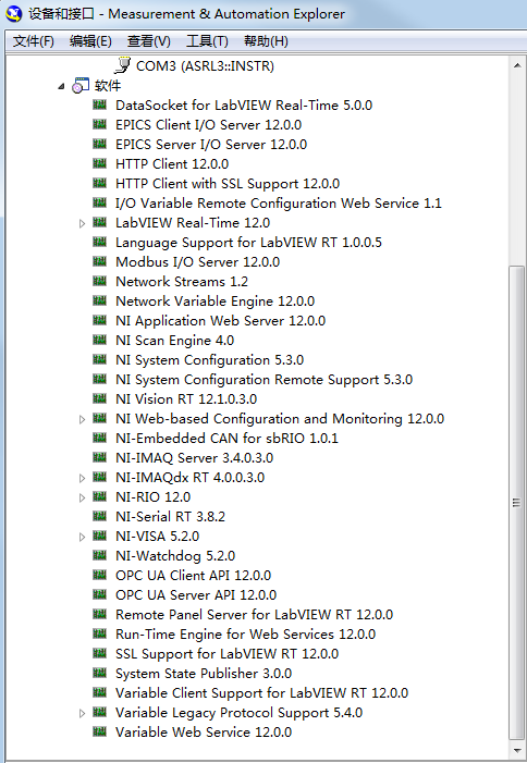
the use of camera web usb on sbrio 9636
Hello
I want to use logitech camera / webcam C170 on single board rio sbRIO9636 to the perception of the vision.
(a) is this unit supported by sbRIO9636, page on http://digital.ni.com/public.nsf/allkb/33131C00626C5B6E8625788D00025FC1 shows that the manufactured by Basler and axis IP camera are supported.
(b) are there any drivers must be installed on sbRIO and where I could find the drivers?
(c) Is there examples for the usb camera capture?
The software is installed in sbRIO9636 is displayed as shown in the pictures:
Thank you!
You will not be able to use a USB camera on a target RT LV.
-
Hello
I'm working on a better solution for my project. I use an Edimax IP camera (model IC - 3110p) I currently streaming using VLC X asset control and then call the node to add the target and play the stream. I was able to find the raw video stream, and I use that as the uri in the control. My project also includes the startup OR Robotics 1.0 kit which has a compact single board RIO on I looked into this as a solution as well, but I think that only the Basler cameras and Axis Network are supported on Compact RIO. The video is streaming OK but I had a lag in like 2 seconds, which can cause problems when I add it to the robot. I was just curious to know if anyone had any other suggestions for this problem. (buy a new camera is not is an option I've tried cheap school). Also, I tried to get audio through VLC as well. When I give the node invoke my raw video (currently http://URL+/mjpg/video.mjpg) disseminates IP camera but let that audio and the invoke node will not accept the URL directly. I'm relatively new to the acquisition of vision in LabVIEW and this is my first post a problem. Any help would be greatly appreciated!
Thank you
Gil
P.S. I do not attach the code I got so far!
Hello Gil,.
Sorry, I completely missed that you posted your code immediately...

I had the chance to try to run your program, and I also saw that there was a disconnect. However, when I tried to start the stream in VLC in itself, I saw again the offset. This makes me think that the shift is from VLC and not communication between VLC and LabVIEW. When I tried typing in Measurement & Automation Explorer directly, there was no lag.
Most IP cameras are not supported by IMAQdx and therefore wouldn't appear in MAX. However, there is a 3rd party utility that can emulate an IMAQdx device based on network flow, of an IP camera, which is contained in this knowledge base article. I suggest that you try to view the stream to the MAX to see if you still see the shift. If there is no lag, then the issue is definitely with VLC or stream.
-
LabVIEW FPGA CLIP node compilation error
Hello NO,.
I work on an application for my Single-Board RIO (sbRIO-9601) and faced with a compile error when I try to compile my FPGA personality via the ELEMENT node. I have two .vhd files that I declare in my .xml file and all at this point works great. I add the IP-level component to my project and then drag it to the VI I created under my FPGA.
Within the FPGA personality, I essentially have to add some constants on the indicators and entries CLIP to my CLIP out and attempt to save/compile. With this simple configuration, I met a compilation error (ERROR: MapLib:820 - symbol LUT4... see report filling for details on which signals were cut). If I go back to my VI and delete indicators on the output (making the output pin of the CLIP connected to nothing), compiles fine.
I've included screenshots, VHDL and LV project files. What could be causing an indicator of the output of my VI to force compilation errors?
Otherwise that it is attached to the output ELEMENT, a successful compilation...
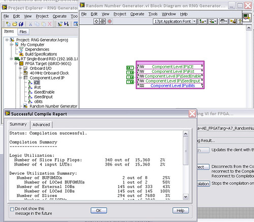
After that the output indicator comes with CLIP, compilation to fail...

NEITHER sbRIO-9601
LabVIEW 8.6.0
LabVIEW FPGA
Windows XP (32-bit, English)
No conflicting background process (not Google desktop, etc.).Usually a "trimming" error gives to think that there are a few missing IP. Often, a CLIP source file is missing or the path specified in the XML file is incorrect.
In your case I believe that there is an error in the XML declaration:
1.0
RandomNumberGenerator
urng_n11213_w36dp_t4_p89.vhd
fifo2.vhd
This indicates LV FPGA to expect a higher level entity called "RandomNumberGenerator" defined in one of two VHDL files. However, I couldn't see this entity in one of two files. If urng_n11213_w36dp_t4_p89 is the top-level entity, edit the XML to instead set the HDLName tag as follows:
urng_n11213_w36dp_t4_p89 Also - in your XML, you set the 'oBits' music VIDEO for output as a U32, however the VHDL port is defined as a vector of bits 89:
oBits: out std_logic_vector (89-1 downto 0)
These definitions must match and the maximum size of the vector CLIP IO is 32, so you have to break your oBits in three exits U32 output. I have added the ports and changed your logic of assignment as follows:
oBits1(31 downto 0)<= srcs(31="" downto="">
oBits2(31 downto 0)<= srcs(63="" downto="">
oBits3(31 downto 0)<= "0000000"="" &="" srcs(88="" downto="">Both of these changes resulted in a successful compilation.
Note: The only compiler errors when you add the flag because otherwise your CUTTING code is optimized design. If the IP is instantiated in a design, but nothing is connected to its output, it consumes all logic? Most of the time the FPGA compiler is smart enough to get it out.
Maybe you are looking for
-
HP ENVY 5530: Printer HP moment of new ink and now can't print with cartridges, I have already
I recently had my printer replaced by HP due to a fault. I was told to just my HP cartridges that I did. However, I am bound to instant ink all with my printer which means now that I can't use the full ink cartridges that I have. Please notice that I
-
Carpet * does not play a UJ - 846 s CDR and DVDR player
I think that the drive is a carpet * a s drive, uj - 846.It used to play and read the CDR and DVDR, but now it doesn't.How can I fix? The computer recognize even there is a disc in the drive now when I put one less than his Blanck.
-
My Photos have disappeared. How to recover?
My Photos have disappeared. How to recover?
-
This has happened for a week now since I downloaded explorer 8! I can't even uninstall so at present can't stop sending this virus from msn messenger. Can I get help on how to stop this or how uninstall msn im desperate now.
-
Windows 7 SuperFetch is not running on the computer.
Original title: windows 7superfetch I am real new to computers, I read some responses on superfetch, do not understand, is not runing, I thnjnk, it should be. Neve got this messge befor. Pleae help