Trainer of OCR OR in LabVIEW
Hi friends,
I am using the NI trainer OCR in LabVIEW module directly which is now accessible only in vision assistant. But it is not loadable, and I'm not able to open the VI it draws vision assistant OCR. Is there a way to call NI LabVIEW trainer OCR?
Currently, the command line arguments, I mentioned is the only way to pass parameters between LabVIEW and OCR training executable.
Once you're done in the training interface, if you have made changes, the software prompts you to save the character set the file at the specified location.
In LabVIEW, you can use the OCR screws located in the Machine Vision > palette OCR open file character set and get all of the properties that have been defined in the training interface.
Watch the screw IMAQ reading OCR Character Set file, IMAQ OCR property.
Hope it makes sense.
Christophe
Tags: NI Hardware
Similar Questions
-
How can I form OCR characters through labview
Hi, I want to do a UI in labview for characters of training for the OCR application. I want to know how I can do this.
-
Recycle the OCR in LabVIEW (retrieve the index of characters found in the set of characters file)
Hi all
I'm trying to recycle my set OCR file in LabVIEW. Basically, I show the reading string to the user and in case something goes not the respective character must be corrected in the charatcer set file, according to the text entered by the user. It sounds pretty simple, but I haven´t find a way retrieve the character index in the file must be recycled. For this I would be needs to know what character in the set file has been found to resemble one give read character. Do you know how I can get this info? I intend to use the OCR rename character VI.
Best regards
Esteban
Hello Arroyo,
You can retrieve the total number of characters formed using IMAQ OCR VI property and looking for property "size of char set.
http://zone.NI.com/reference/en-XX/help/370281W-01/imaqvision/imaq_ocr_property/
Kind regards
Elli
-
DC 4276 bias introduced by Labview
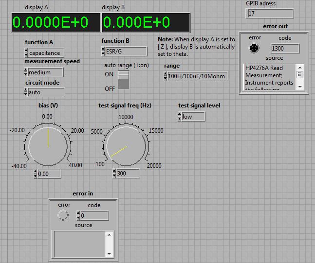
I work with the meter of LCZ 4276, and I downloaded and installed the driver for it. However, I opened the example VI and it seems to work except it puts an error 'ERROR 1300' in Labview and on the instrument really it shows "ER 13".
I talked to my colleagues about it and it seems that there are some hypotheses of labview over the instrument. In the manual of 4276a (Section III, 3-14) (page 56 in pdf format), it is said that this error occurs if internal polarization DC voltage has been set via the HP IP but the instrument is not equipped with Option 1 (which is a DC Supply), or it occurs if the comparer enable code (E1) was sent through the HP - IB , but the instrument is not equipped with option 2 (which is a comparator/Manager interface).Well, this 4276a does not have the option. The switch on the instrument that turns DC polarization is off. However, as you can see from the picture showing my error, it is a DC bias in the VI himself.
So I ask myself, how I would you turn off the DC bias or LabView to stop running? I looked through the subVIs that make up this example.VI, and there is no code which entered the channel 'E1' for the activation code, so I don't think that the error occurs due to Option 2.
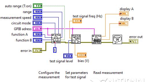
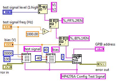
I have added the block diagram for the example.VI. In addition, I added the Subvi (ConfigTestSignal.VI) that contains the DC Bias input.I would like to know what you think. Thank you!
Hello Erny123,
I have not read the manual, but I guess that BI is a string that specifies a configuration of bias, and indicates the end of the command. "%.1f" is a format specifier that inserts a value decimal floating point with a figure of precision (see this link for the syntax requirements when you use the Format function). Right at the top you can see that a similar format function is used to insert the test frequency in the chain of command using EN rather than BI and a slightly different digital format.
The example you are using was not written using the standard style of LabVIEW, it can be a little difficult to follow the entries and exits to go where. Try to click the icon own schema in the block diagram of example to rearrange things in a more logical way of left to right.
That makes this VI composed a string of commands to send to the device - you need to consult the manual to see what are the requirements of presentation, but I guess you can just delete the second format value function and wire the output of the first through sending message VI.
I wouldn't say you have to start from scratch every time, but yes, you will need to make some changes in this example so that it can work for you. I highly recommend that you go through one or more of the LabVIEW tutorials available online, it will save you a lot of time in the long run.
If you have an active support contract and your serial number of the software has been activated on your account of ni.com, you should have access to the basis of LabVIEW training online here:
OR Online Self-pace free-training
If you do not have access to that, there are a number of other Introduction to LabVIEW tutorials available on ni.com links on the right side of this page are a very good starting point for online tutorials:
LabVIEW academic training: how to learn NI LabVIEW
http://www.NI.com/academic/labview_training/
Kind regards
-
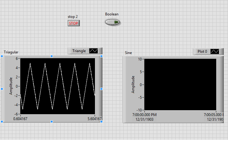
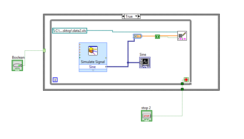
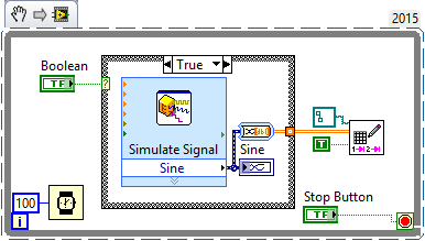
I am a beginner. I'm trying to create a simple VI only switches beetween two types of signals like sine and triangle when someone press on the push button and at the same time, save the data in the file to my desktop. I also have a stop button which no longer record data. Here are my questions and dproblems:
1. when I press the button, it does not the true and false in the structure of the case so that I can see the triangle wave stops and begins the sine waveform table.
2 when I press the stop button, I want the program still running, but the process of writing data in time the loop stops. I don't mind if the graph of the wave stops too but it would be better for the user to see the wave form is running, but the data will stop recording.
3. Although the condition of the loop did not accept the local variable for the stop button inside the loop or within the structure of the case, so I put the button outside all the loops and the structure. (I know that this is a problem, I do not know how to use a single button several times in a single code. The local variable did not work the world premiere? I have to?)
4. the data file it creates hase a lot of lines and columns. I expect a time column and a column of mixed signals based on the push button amplititude this user press every time. I did that with the acquisition of data and a sensor, it automatically gives me the voltage and time in a column. I tried 2D and 1 d and it has not changed anything.
Thank you for your help
Like you said, you read only your entries at the beginning, then whatever value they had before you hit run is worth to be seen by the rest of the code. Programming LabVIEW is based entirely on the data flow and parallelism. It is incredibly powerful and has led to its success over the years (coupled with graphical programming), but is usually one of the first things the new developers stumble on. This is a simple resource to familiarize themselves with its functioning. The function to highlight execution is a great way to watch how your application uses data streams.
Simple code goes like this:
- Containing the main code of while loop
- Inside of the whole loop is all user interaction code or modify the code entry
- Stop the terminal loop is attached to stop certain criteria or user selection of a stop button
- Loop initialization above all if necessary
- Closing referrals and communications, etc after all loop
It's very simple code. If you want to watch in more advanced architectures that are scalable, Google "LabVIEW State Machine" or "LabVIEW producer consumer."
If you are just starting, you should do a free training have the capabilities of LabVIEW.
"Give me six hours to chop down a tree and I will spend the first four sharpening the axe. -Abraham Lincoln
Here are some free training focused mainly on LabVIEW and hardware tools to help get started.
-Guide of MyRIO project Essentials (a lot of good simple circuits with links to youtube events)
Learning OR training videos resources
Introduction to LabVIEW for 3 hours
Introduction to LabVIEW for 6 hours
Paced self-study for students
Self Paced Training beginner to advanced, required SSP
LabVIEW training Wiki - Containing the main code of while loop
-
redeclenchables out initial varaible on each trigger with delay
I'm trying to implement a redeclenchables generation digital pulses of the train on 6363 PCIe with LabVIEW with the additional feature of an initial delay variable.
For example:
-J' have a fixed pulse train
-After the 1st trigger, it is generated without delay
-2nd after trigger, there is a delay of 10µs
-Each subsequent trigger increases the delay of 10µs
I tried to do by writing new samples to the digital output, which include an initial delay. Since it merely controls how the buffering is managed this does not seem to work reliable with reboot and redeclenchables ouput.
Is there another way to do this using a perhaps additional internal counter for the generation of delay?
Thank you
Christoph
I would look at using an additional counter that your delay generator. There is a counter property called
Delay 'auto increment Count', which lets specify you such a regularly increasing. Here is one
DevZone article and example that should help get you started.
The idea is that the extra meter comes between your initial trigger signal and the
pulse train finish that you want to generate. The additional counter made its own triggered impulse
with time growing after the initial trigger and your finite pulse train gets triggered by
This additional counter output.
-Kevin P
-
Reads OCR training character, but not the program labview
I am training characters, then check my program is able to read the same characters. Every article I read has 8 of the same characters in different parts of the King. Because it is a curved surface, each position is formed independently. 3 the posistions, I formed the character '5' and it will recognize without any problem in the roc training program. Using the exact same ROI, it will not read the characters in my program. All settings, IE the resolution read, read strategy, erosions, etc. are the same in both programs. It notes the character, don't know what it is. I use non-linear threshold. Indicator report of character, I took the threshold values, it uses in my program and is entered as a range threshold fixed on the formation of ocr. This turned the blue character just as expected and read without any problem. Unless there is a setting I'm missing, it seems that the OCR Application does not use the text for reading OCR Idem 3 I use in my program. Any suggestions? I know it's complicated, I'll add the image and a screenshot showing what I mean
I fixed it! I became crazy and set all the properties of ocr, even those I was using just the default setting. Weird.
-
Bounding box character labview OCR code
OR na no escape codes and examples entirely for Vision Assistant so I have to use the Assistant whenever I train some characters.
I want to add the simple workout for my main program routine.
As a starting point, I would like to detect the character bounding rectangle of OCR object (like a red of attachment box) before reading a character set.
Y at - there no related vi for this work?
labmaster.
*) OR read LCD/LED.vi does not work for my purpose. abandoned after investing time and different camera.
NEITHER provided labview code in the Panel of the OCR.
-
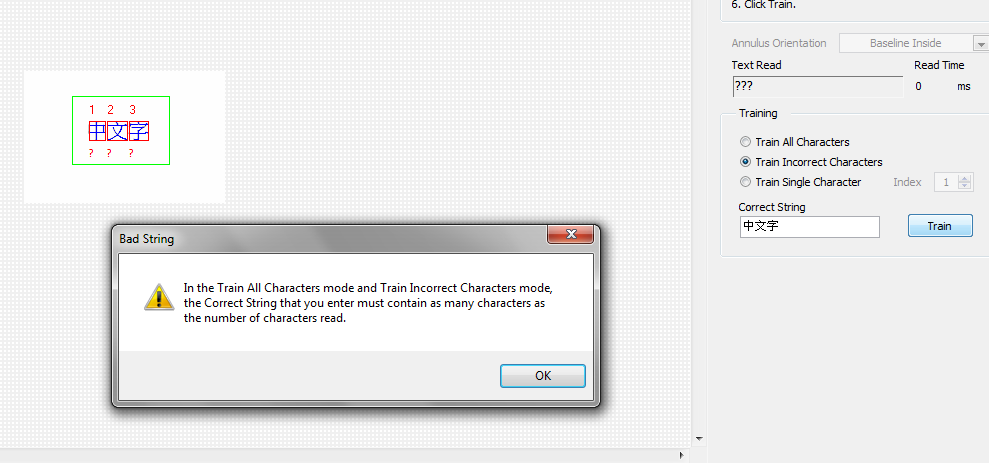
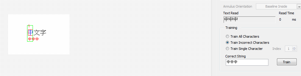
OCR training on Chinese characters
Hi all
I want to recognize the Chinese characters via OCR toolkit
In regard to English characters and numbers, I could train chacters several at once, say "abc123".
When I, however, form several Chinese characters, it will come out of bad character number warning popup.
In additional, it may appoint one character to several Chinese characters.
This means that I have to form Chinese characters one by one, never all of the characters?
Chinese characters are not 'effective' for the toolkit characters LabVIEW OCR to process individual and may not treat them together to deal with.
Could someone give me some suggestions? Thank you very much.
I think that Chinese characters are represented in the operating system by several characters, probably a sequence of two characters. Even if it is displayed as a single character, for LabVIEW, it seems that you type two characters. It might be interesting to verify this by checking the length of the string in LabVIEW.
I think that the formation of character both would work well. If you do a lot of training, you could write a quick utility that loop over each unknown character and ask the correct character, resulting in the formation of a single character at a time by a long sequence of characters.
Bruce
-
LabVIEW, c. 8 training c. 2014 material
Industrial technician basic training in LabVIEW, a reference book for version 8 do work well with the current version of LabVIEW 2014 student? For example, menus and screenshots of version 8 still viable for 2014 of learning, etc. ? If the new reference materials are needed, which recommended it?
Thanks, people. These are very useful comments and suggestions.
-
I'm using LabVIEW 2012 evaluation of training mode in order to find a location using LabVIEW. A MVC tutorial looks like a very good example and I can open the first VI, Starter.vi of MVC, but when I try to open the project which includes screws to MVC OOP advanced with controls and Factory.vi, it must IMAQ live but when I try to install Vision in order to get the screws IMAQ, it needs LV 2011 installed in order to install the Vision and will not proceed with the installation of Vision/IMAQ.
After searching the site OR days to get responses LVOOP I found this tutorial that could be useful, if it's actually working.
Setup of Vision should probably work with 2012, but the installer was not setup to work with 2011 or later.
In addition, I have not found a good description of what the MVC "framework" is all about.
I used LabVIEW since the beginning of the 1990s, but not from my NI Suite which included LV 8 and LVOOP about 2007. I desperately need a step by step "how-to and why ' for LVOOP, ACTOR, etc. I'm through the core I and Core II manual of training for certification, but it needed LabVIEW work as soon as POSSIBLE and do not have the $2,500 to upgrade my NI Suite or $10,000 for training or time to complete certification now.
It seems that every time that I start to make progress and NI LabVIEW, I hit a roadblock. Nothing seems to ever work as announced.
Help, please!
First, you must determine what version of LabVIEW, you: 2011, 2011 SP1, 2012, 2012 SP1. You can find this by opening LabVIEW and navigate using-> on LabVIEW...
Then, you download and install the compatible version of the Vision Development Module. Here is the link you should use:
http://www.NI.com/downloads/products/ (search for Vision Development Module).
In addition, there is a driver software that exists that is called Vision Acquisition Software. But, if you do not interact with the hardware at this stage, then you don't need it. Here's a better explanation:
What is the difference between software Vision VDM, VBAI and going TO?
About MVC, I'm no expert, but you should know what a MVC is and understand LabVIEW and characteristics before you dive into this example of MVC in LabVIEW. My recommendation is to not try to understand/learn MVC for the first time looking at this example. More information can be found by conducting a search on any search engine. Here is the Wikipedia article.
-
The interface OCR training manual
I need to know the different options and their uses in the interface of OCR training as a format of image (in terms of how it determines the recognition), bi modal inspection, precision of speed etc...
Can someone help me...
Hello
Chapter 18 of this document will help you to:
Concerning
-
Hi guys,.
I'm having a problem with OCR function test. The error I get in return is IMAQ OCR attribute-1074395583. This happened just today after I made changes to an existing application. I had no problems with this before and also nt have made updates to suggest that this was the cause of it. I wonder if it's a question of repertoire that it cannot find the file?
Thank you
Damien
I'm not sure unless I see the character of code and ocr set (if you can provide, it will be easy to know where it happened)
-You said you have amended the application, have you you edit the code or the file character set?
-You use assistant vision or labview?
-Check that the character set the character spacing of the file Min in NI OCR training Interface. -
Greetings,
I am very new to machine vision, I am creating a number plate recognition system, I trained each character set in the license plate in the formation of OCR and when im opening each individual character image, sound successfully converts it to a string, but to an entire image (of the plate) its does not (I'm '?') I tried using KING for selection of specific areas but does not work... I don't know what seems to be the problem please help.
You must connect the region of interest to the vi IMAQ OCR read text 3.
The following example shows how to use the screw of OCR:
C:\Program NIUninstaller Instruments\LabVIEW\examples\Vision\2. Functions\OCR\OCR first Example.llb\OCR first Example.vi.
With this example, you can even load your character set file and try on your images.
I hope this helps.
Best regards
Christophe
-
Using a neural network with box Toolbox MATLAB in LabView?
I would like to know how to train a neural network in Matlab and use it in Labview? I know I should be using the MathScript, but as I do once the network formed in matlab is a dull file?
Hi GringoButzlaff1,
Well, it's not all MATLAB code/script that can run in LabVIEW using MathScript.
If there is a function of IP (intellectual property) in the code, that is, any Toolbox MATLAB functions, you won't be able to execute it using the MathScript.
In fact, you must call the MATLAB script node in your code. This node calls the script software MATLAB server to run scripts written in MATLAB language syntax and are only available for windows.
Try encoding using the MATLAB script node and tell me if it worked for you.
Best regards.
Maybe you are looking for
-
Lightning don't talk to Google Calendar - problem with cookies?
Execution of Thunderbird 31.1.0 with Lightning 1.0 and the module supplier of Google. I maintain four different calendars with google (work room, home, other, conf) account. When I woke up today all my calendars worked. They have been set up in light
-
HP TouchSmart tm2t-2200 CTO: drive recovery system for laptop HP TouchSmart tm2t-2200 CTO
Anyone know if the recovery disk Windows 7 for laptop HP ProBook 640 G2 is compatible with the HP TouchSmart tm2t-2200 CTO Notebook PC? When I bought the Tm2 a few years back, I not create a system for her recovery disk. Now that I have the ProBook 6
-
Spilled Coke, not too loud low speaker
As the title suggests, I spilled coke all over my phone. The phone screen still works, but I noticed that the low speaker is much milder than the speaker at the top of the page. I know the imbalance in volume is not because of the lollipop bc update,
-
Windows live photo gallery; How to put the Picts in a specific order
I can, t find a way to put pictures in a specific order in windows live photo gallery.
-
Hello I have a security problem on my Q10. Some sort of spyware has been installed, I did a Wipe of security but I have doubts if it is deleted. Could you please help and tell me what can I do to erase all data on my BB and that system restore? Thank