Triangular signal on fpga
Hello
I am trying to create a triangular signal on a FPGA target, I can compare it to an analog input signal, so I can create a PWM signal. If you can help me generate triangular signal on a target fpga and I was wondering if using a simple comparison just to compare the two signals point-by-point?
THX
Hello
Please contact us.
If you want to do something like this: http://decibel.ni.com/content/docs/DOC-2387 , you can try it.
Simple comparison is enough, but if you have a noisy input signal, you must use a filter.
Kind regards
Peter
Tags: NI Software
Similar Questions
-
Greetings,
I did this VI, but there's a mistake in there and I don't think it's solvable like that.
The triangular output signal should start when I press the Boolean value. Otherwise, the DAQ Assistant mette 0V.
When I press the button stop the DAQ Assistant also needs to 0V
Is there another solution?Thank you
Hello Innervision,
I suspect that this issue is related to the following forum post:
http://forums.NI.com/T5/LabVIEW/analog-output-signal-stops/m-p/2321672#M728
677I will continue the discussion there, because I've already posted my question there.
-
Best way to generate signals of activation (square wave) with my 9401 on my 9022?
Hi, I tried seriously over the past two days to find the best way to do it. I am trying to generate a very precise square wave, controlling the duty cycle and frequency, with the OID on the 9401 in testbed cRIO 9022.
I have a VI that is theoretically able to do this, but whenever I try to go above 5 Hz or more, duty cycle and frequency becomes inaccurate (I have watch on an oscilloscope), various a lot too for my needs. I have a feeling that this is caused by my addiction on the calendar software controlled, with errors at the time (of the ms order) accumulate as they get processed and the signal is sent. I have attached a piece of code that illustrates the basic idea of what my VI have in them.
I have avoided the square wave generators integrated because I could never work to satisfaction, but I can work with them so that will solve my problems. Selection structures and cases prevent the user to exaggerate their inputs. Unwaited so the loop was just to test.
I'm running the 9022 as target in real time, but also tried to run in the FPGA and I was able to produce much more accurate signals using FPGA VI square wave, displaying a Boolean variable, but I couldn't see the best way to get double precision variables to work with everything (and I want more precision than variables FXP enabled clock 40 MHz).
I feel there is just a mistake in my approach here. I've seen other discussions where people throw around using meters to edge of the test bench to produce a square wave, and I see the example screws as Gen dig pulse - continuous Train, I'm not sure if initially these screws DAQmx for my situation (eg. How to identify my counters, because they are clearly not Dev1/ctr0 by default in these examples)
Thank you
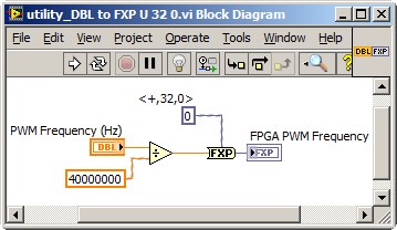
Dealing with the representation of Point fixed and all is a reality for LabVIEW FPGA<= 2011="" programmers.="" you="" might="" build="" a="" small="" sub="" vi,="" such="" as="" the="" one="" attached,="" to="" encapsulate="" the="" frequency="" calculation,="" thereby="" abstracting="" the="" conversion="" formula="" and="" fixed="" point="" data="" type.="" you="" can="" adjust="" the="" properties="" of="" the="" floating="" point="" input="" control="" to="" accept="" only="" valid="">
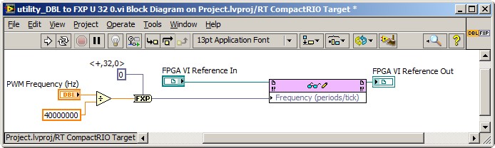
This implies the series VI void on the host of the RT, and not on the FPGA target. So, you also need nodes in the Palette of the FPGA Interface to send PWM fixed Point RT frequency to the FPGA. The complete solution of frequency may resemble the following. It is common for FPGA programmers to build a collection of thesesub screw, that make up the API for hardware.
Note that 40 MHz is hard-coded. For increased flexibility, consider making the FPGA clock rate an entry to the Subvi with a default value of 40 MHz.
-Steve
-
VI quadrature encoder does not work after programming of FPGA
I'm rather new on the MyRIO, and I work on the motor of the MyRIO and read control in a quadrature encoder at the same time. Programmed individually, the two pieces of work at Marvel, but once I have combine them and try programming, control of motors not to not work signals, but the reader encoder does not work. I use the Express VI for the LabVIEW quadrature encoder reader, and I produce four stepper motors signals using FPGA.
It seems as if the encoder is disabled when I program the FPGA with my code, because if I have two parallel loops, one for the reader encoder and the control of step motors, if I stop the loop of step motors, the encoder works immediately.
Is there something simple that I'm missing? Any suggestions would be greatly appreciated!
Thank you
Enan
I realize now that my last answer could have been confused and not useful to someone else who may come across the same problems later.
Here is how I solved the problem I've had:
I had to derive Boolean expressions for an encoder quadrature (essentially to create my own) and then used the outputs (UP, DOWN) to increment/decrement a counter using the conditional statements. Then, I stored the value of direction in a flip flop implemented using two conditional statements of T/F in series and connected to a shift on the edge of the loop register.
It was all able to be implemented in a single cycle timed Loop, and then I managed to place in the same loop that I used to control stepper motor.
In this way, I could have a VI collected in a Bitfile and could be programmed to the FPGA.
Hope this is clearer!
Enan
-
optimization of signal for MEMS applications
Hello guys,.
I hope that I will find more help here than on the french forum!
OK... Here's my problem:
I'm working on MEMS technology (Micro electromechanical system), it converts the electric signal into a movement.
My entry is a voltage vs time signl V (t) = SUM (I * sine(w*t+phii) I = 0--> 3)
My output is the displacement of the MEMS (t) Z. This displacement is measured.
Since my entry and exit, I can draw Z (V)... and it has a fairly complicated shape... so what I do is I change manually 'have' and 'Phil' until I get Z (V) = alpha * V + beta on the quarter (V is sine wave)... Or, in other words, do Z (V) triangular signal
I have to generate a vi that reads "IA" and "Phil", can change until I reached my goal.
I used Labview 7 years ago (and I thought beginner mode), now I feel I lost my abilities... and I work at the level of the hard mode.
I hope to find clues to solve my problem here
Thank you
I don't know whether you mean something like what I send an attachment
Test it
It uses a step for one and pi that you choose and also accuracy -
FPGA SIT VI disturb application feature!
Dear Sir/Madam,
I have a question about FPGA combined with the Simulation Interface Toolkit and I will be happy if you could give me some advice!
I have a HiL application that is based on the following:
-Host VI on Windows PC.
-VI driver on the system in time real VxWorks on CompactRIO 9014.
-VI FPGA, which contains 2 nodes of e/s which I use to swap frames with an external CAN CAN network to control a machine'S FPGA-VI-controls that represent the different channels of the Messages CAN get their signals through FPGA mappings that I set with the SIT connection manager.
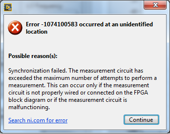
My problem is how to get the best time for the FPGA VI to synchronize it with the driver VI. The default method, I get the model comes from the interruptions. Although my FPGA target 9104 supports interruptions, when I run the Application and after the deployment of all the screws on the cRIO target, the simulation stops and I get an error: (see attached screenshot).
I wonder why the request could not be started when it is connected with an external CAN network, because when I tested it with a cable loop (I connected CAN 0 with 1 CAN leave the Modul NI 9853 CAN with a CAN cable), it worked without problem.
So I will be grateful if you could explain to me how can I change the FPGA VI or VI driver to get their work together!
I have also attached my FPGA VI.
Thank you in advance!
--
Yours sincerely,
Mehdi MeddebDetails of software zur: LabVIEW FPGA 2009 version
Material: RIO (cRIO, series R, FlexRIO, sbRIO) device CRIO-9014, NI 9853 CAN
Driver version: NI RIO 3.2
Operating system: Windows XPHello Andreas,
Thank you very much for your answer!
The problem was exactly what you explained! I wonder why the default value of the timeout is so great!
Fortunately, I found the solution for a week, and given that the application works well!
A big thank you once again and I look forward to hearing from you soon!
-
L755 satellite internet connection drops but stilll connected to the network
Hello
I hope one of you can help me. I have a laptop 13 q Satellite L755 nice for a year and a half.
My problem is that I surf the net and suddenly my internet connection drops down. On Firefox or IE, I have a message with a triangular signal yellow saying: "your connection has be revived."
I'm still waiting on my network but I can't access the internet.The strangness, is that my family other PC or laptop have no problem on the connection.
This happens on the wifi and cable. At home or other places of connection.
In France and the United States. So my conclusion is that there is a problem with my laptop.I looked around some forums. It seems that some have a problem with IPv6.
I have disabled the option to use IPv6 on my laptop, but I still have the problem.Another comment: I play the Kingdom of the fortress online.
Sometimes I disconnect from this game but I can still surf the internet for a few minutes before undergoing a total disconnection.Looking forward for your help.
As this happens using WLan and LAN its really hard to say why your connection is interrupted.
Have you tested the internet connection with fresh preinstalled system?
I mean it is possible that some software / updates received or installed in the past it would affect. -
Problem of generation of Sync trigger in several synchronization USRP RIO 2943R problem
Generation problem shutter Sync in several synchronization USRP RIO 2943R problem.
Previous SR you may already know I'm stacked in USRP RIO multiple synchronization problem, especially in the mode based on the signal. Now I can cut down, the problem is mainly due to the outbreak of sync signals generation.
First of all, I read the article and the discussion in the following two links:
http://forums.NI.com/T5/USRP-software-radio/how-to-synchronize-multiple-USRP-Rio-294x-devices/TD-p/3...
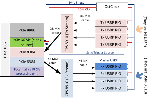
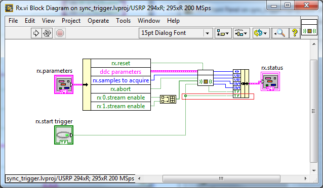
http://zone.NI.com/reference/en-XX/help/373380D-01/usrphelp/synchronization/and I did my connection of the material according to the suggestions in the second link. My system schematic is shown in the following image:
I checked OctColck and SMU 6674 T connections. They are all connected correctly and the cable are fine. I use the niUsrpRio200_XcvrSyncPps.lvbitx.
According to the description of documents and discussion forum, the USRP RIO 1st in the list of devices are considered to be the USRP Master. Then, the FPGA to master USRP RIO released "trigger of sync" signal through the 'PPS Trigger Out' SMA port in RIO USRP box.
Based on the my analysis of the system, the first impression I have is the USRP Master does not export the 'sync trigger' correctly. The host VI reports the error like this:I was trying to measure the "synchronization trigger" using oscilloscope, but I found that it is impossible, because the host VI can not yet run, so there is that no signal can be seen from port 'PPS Trigger OUT.
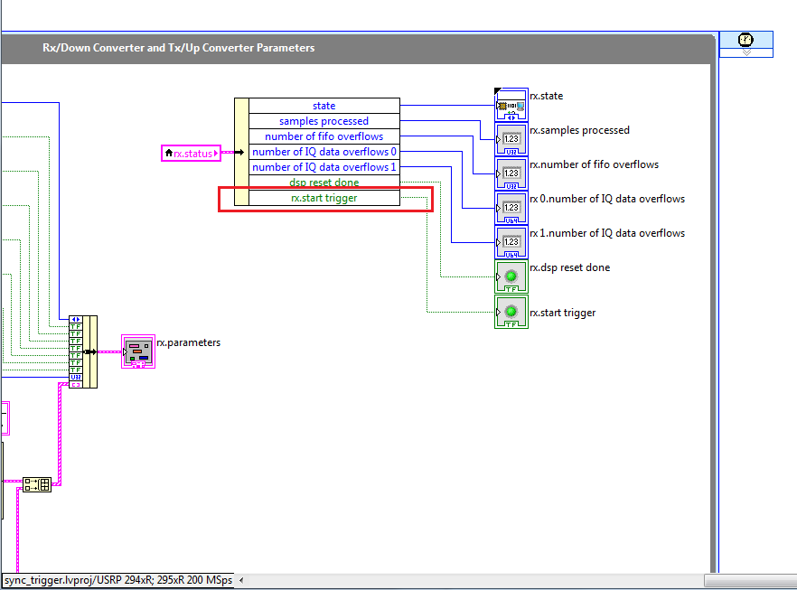
So I think that if I can watch this signal "sync trigger" in home VI by importing this signal from FPGA to host VI. I did some changes on the FPGA VI as shown in the following image to watch this signal of façade of the host VI. but not so successful. the rx.start tragger relaxation and tx.start do not appear on the host vi read/write control function.
-
NEITHER 9234 fifo dma file samples
Hello
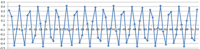
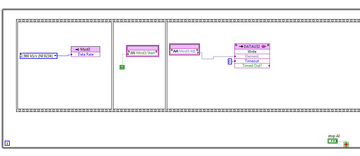
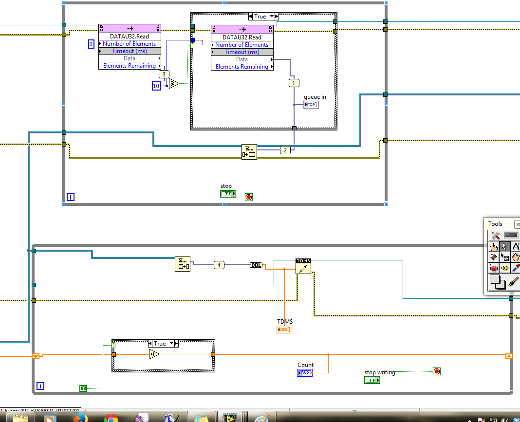
I have a problem when sampling using the cRIO and map AI NI 9234, currently configured to sample a signal of Hz 1 k of the side signal generator FPGA goes directly to the DMA which is (1023 elements in size) on the side of the host (size of the element 1 million). With the help of the producer, architecture of consumption and saving on PDM on the consumer side. The producer has read dma fifo. Please see pictures any help would be great!

If I plot the data, I get this:
Here is my code FPGA:
Here is my version of the host:
Hello
The problem has been resolved on this post.
Thank you
-
Photon counting using the FPGA of the series R. problem generation TTL signals
Greetings,
I try to use the R series FPGA to read and count the pulses TTL of a discriminator (count of photons of the Hamamatsu C9744 unit) connected to a PMT (Hamamatsu-H7422P-40). The release of PMT looks fine (signal.png H7422P-40) but the discriminator wasn't able to generate corresponding TTL 5V pulse. There was some scattered and random spikes, but nothing significant. Instead, the only stable the PMT signal is a single + 5V pulse no matter how, I adjusted the PMT (C9744 output.png) control voltage. The PMT and the discriminator is connected by an ordinary BNC cable 50 ohms.
I am really confused because it was supposed to be a really simple installation. Anyone have a similar question or have similar Instrumentation (but no problem) configuration? Comments/suggestions are greatly appreciated.
Thank you very much in advance!
Hi Kelli,
Thanks for your help. Sorry it took so long to get back to you.
I actually found the question. The discrimination of the Hamamatsu unit level is set too high that all signals got filtered. After adjustment of the threshold of manuallyt, I was able to get the camera TTL pulses. And 7842R worked correctly for count impulses. Everything works fine now. Thanks again for the input.
-
CRio, Ethercat 9144, Ni9264, FPGA RT, cannot send signal AO to 9264 in Ethercat 9144
Greetings,
I am trying to send write them in a host program to a "user defined variable" AO for a NI9264 located in a module of Ethercat 9144, as the 9144 does not support an interactive control.
The FPGA vi compiles successfully but I get the error that the variable defined by the user that is associated with my AO control does not exist.
I can read values from other modules in the Ethercat 9144 crate from a host computer, but cannot write to the AO 9264.
Any ideas what I am doing wrong, other on the assumption that it is possible to perform this task on a CRio system?
Thank you
Jim
Hi S.,.
Thanks for the help. The problem has proved to be a problem with the installation of "User Defined Shared Variables." For the analog output of the module there is a tab in the shared property Variable that must be set to "Host to FPGA", for analog signals, it will be "FPGA to host."
Simple enough, I got a couple of them set up correctly but not all of my AO, so I got the error. And then, I got a question bitfile has been loading for the FPGA, a lot of things to follow, but it seems to work fine now.
Thanks for your reply, I feel into a solution reguardless.
Jim
-
MyRIO FPGA read framework signals SENT
Hello community,
I now have a myRIO with Labview 2013. I try to read a digital signal to a sensor on the port DIO0 (C-Port). It works very well. The problem is that I don't know how to find the start (the SYNC nibble) of the frame SENT - and how it works with the ticks of the clock / time clock of the FPGA (40 Mhz) system. I do not understand the meaning of the clock. ticks of the clock.
The next problem is to measure the time between a front down to falling edge. In fact I can detect every falling edge of the signal SENT but I cannot measure the actual time between them. How can I measure the real time based on the system FPGA clock time? The nibble of SYNCHRONIZATION were all 56 time graduations. But how long are 56 ticks?
Best regards
Basti
Hello, Alexander.
Thank you. It works very well.
Now my problems are solved. The main problem was to build something that is capable of converting 56 ticks of the SYNC signal SENT for correct ticks of the sampled signal. The two frequencies, the Signal SENT (333kHz) and the sampled signal (40 Mhz) are different, so I divided the frequency of the signal sampled frequency of the Signal SENT - (factor of about 120). Now I can convert 56 ticks to correct the number of ticks of the sampled signal and I can find the SYNC - Puls in FEEL. The result of 56 times the factor of 120 ticks is 6720 ticks. So, I convert ticks to the correct frequency.
Thank you very much for your help!
Best regards
Sebastian
-
Exhibitor block signal - Xilinx FFT v7.1 - FlexRIO - FPGA
I use Xilinx FFT v7.1 IP (FPGA - OR 7965R, LabVIEW 2012). I am computing the FFT of real integer 16 bit signed.
Bit 5 signal exposing block block floating point FFT in module v7.1 Xilinx FFT signed or unsigned? Pdf document talks shift to the right of the data output to use the dynamic range, mentions not moving to the left, neither gives sufficient detail on this subject.
Is there a base value as format IEEE floating point should I use to find the correct output value?
I guess that it is unsigned unless you have comments to the contrary. The basic behavior is to keep bits on the left in order to prevent any overflow, so the scale always implies move on to when you think that some of the more significant bits are unused. They provide an example of b00101 = 5, so that indicates there is no bias to apply.
-
[FPGA] Problem with the sinusoidal signal generator
Hello!
At first I want to apologize for my English is not my mother tongue.
Hardware and software I use is:
LabVIEW 8.5
NEITHER RIO 2.4.1
NEITHER cRIO-9014 (controller in time real CompactRIO)
NEITHER cRIO-9104 (chassis and FPGA)
NEITHER 9264 (16 channels, +-10V, 16-bit voltage analogue output Module)
I made a very simple FPGA VI: a while loop, generator of sinusoidal signal and a FPGA of e/s node in the loop. I've specified the Gnerator settings by following the path:
Frequency = 50 Hz
Amplitude = 1
Phase shift = 0.00
Size of the table look-up = 1024
= 16-bit amplitude resolutionFPGA clock frequency (40 MHz)
But the wave of "sine" I got is not what I wanted to get. First of all, its amplitude is 1 V. shouldn't it be coded on 16 bits? If I wanted to get 1V I should have specified Amplitude as a 3277. In addition, 'sine' is not very detailed, it's look like "steps", as many samples vere missing. What I did wrong? I checked the samples and tutorials, I did everything the same way. A I forgot something or not has not specify other parameters?
Thanks a lot for your help!
OK, I solved a problem. It's embarrassing to admit, but maybe this will help someone else
 I blame my inexperience
The main solution to the problem was changing calibration of calibrated RAW Mode. After that, everythoing works as expected. I had a problem with a sample because I was using a multiplier to control the generated sine wave amplitude. But... She was set to 1 in the sinusoidal signal generator. That was the reason for waveform Gradin. Please, don't laugh too much

In any case, thank you for an answer! It is now resolved
-
FPGA: the internal signals in ModelSim display
I have a piece of code written LabVIEW FPGA in that I am trying to simulate in ModelSim. I followed the instructions in this link, but the example is a simple incrementer with no internal signal (only the input and output).
I created a test bench and started the simulation, but the macro provided .do only adds the entries and exits to the wave window. ModelSIM lists pages and pages of processes and signals that can be added to the waveform window; all have names completely opaque. I found something called 'TheWindow', and then a subdirectory called "Thatcher" and added all these signals to the waveform window. The names are things like ResHolder00000000000001 and provide no information on where they came from.
I tried to assign labels to the sons of my LabVIEW diagram, but that did not help at all in creating useful names. I need to check the progress of States in my VI but can't find anything that seems like the appropriate signal. A lot of available under 'Thatcher' waveforms are waveforms static, uninitialized, or both. How can I assign names to internal signals so that the waveforms are actually intelligible?
On a side note, it is also a problem in the synthesizer. I'm used to using the synthesizer output to 'pre-debug"my code, but LabVIEW seems to ignore the process of inference any macro. I tried to put a SCTL with an incrementer and LabVIEW does not infer a counter. I have never seen one of my machines of State recognized in the synthesizer, even if the code works correctly.
Using ModelSim PE 10.3, I understand is not "officially supported", but the fact that the synthesizer and the Simulator have the same denomination made problem wants me eliminate this as a problem. I do not use one of the PE extensions on the version SE.
Hi Nick,
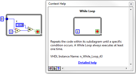
If it is not the most readable, its not too hard to find signals that you are looking for. Your biggest help will be context-sensitive help in LabVIEW. If you hover over the structures, nodes, or son, in your LabVIEW FPGA design, at the bottom of the help context window, you'll see what we call the 'name of the VHDL Instance".
Once you navigate through the hierarchy down through the window, in the VI, you should start to see some of your top-level objects, such as while loops etc. From there, you can navigate down in whatever the level and find the wire you are looking for.
I did not have the ModelSIM on my machine, but it works for the ISIM. I wish they had a search function, so you can just type in the signal you are looking for.
Maybe you are looking for
-
IPad has the latest updates to iOS. Is there a way to limit the number of messages downloaded from my Verizon account. for example, download only the last 30 days?
-
iTunes automatically checks all my pieces purchased at random times
It absolutely makes me in the wall. For some reason I don't understand quite, iTunes checks ALL the songs that I bought in iTunes which seems to be totally random times (but it looks more whenever I do something with iTunes these days, it happened tw
-
Discover the 1280 X 1024 on s1931a without distortion
Hello- is it possible to change a resolution of 1280 x 1024 on my new s1931a without distortion? I don't care if it shows with black side bars. currently when I try to do this in windows 7 it distorts the image (fun vertically it fills the entire s
-
Photo of BlackBerryContact at EncodedImage
Hi, I want to get a byte [] photo EncodedImage in the BlackBerryContact, how can I do this? When I try to do, an illegal argumet exception is thrown by the createEncodedImage (byte [] b, int offset, int length); I call it like that byte[] binary = co
-
WARNING on 13/10/2011 11:06:08 Kernel - PnP 219 (212) Log name: SystemSource: Microsoft-Windows-Kernel-PnPDate: 13/10/2011 11:06:08Event ID: 219Task category: (212)Level: WARNINGKeywords:User: SYSTEMComputer: Buzz_Murdock-PCDescription:The driver fai