Trough come reading USB TTL signal
Hi all
I am currently working on a project for my internship. For this project, I need to connect a GPS to my PC. So far, i've got material that generates output a NMEA asynchronous serial connection (TTL) sentence. Here you can see the diagram of the card. Now, I need to connect to the PC so that I can get the bits in labview. My current idea is to use an FTDI cable to convert the data in USB TTL and that plug into the PC.
Now, I have a few questions:
-Is a good way to connect the device to my pc
-How to collect data from USB in labview
-Have you guys any idea about connection/reading data to do better or to use a completely different approach?
Kind regards
Jesse Bax
Student Mechtronics
In what concerns the data "collection". NMEA compatible GPS send continuously in the form of "sentences" NMEA data, you do not querry it.
These phrases are just ASCII text, you must capture and analyze the text to get the information you want.
Here is a good discussion on the decoding of the NMEA sentences.
http://www.gpsinformation.org/Dale/NMEA.htm
Tags: NI Software
Similar Questions
-
How to generate a continuous ttl signal with a USB-6501
Hello everyone,
I am a beginner with LabView, so maybe my problem, it's very easy to fix.
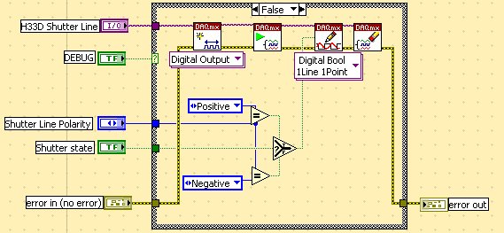
I need to generate a digital output using a USB-6501. This TTL signal will then switch to a device. Basically, I need the digital output to be permanently to TTL high level until a user active departure is given. Then the digital output must stay to the TTL low level until another stop active user is given.
Does anyone have any suggestions on how to do? I have failed so far to get something different high TTL to my USB 6501.
Thank you very much.
Hi there, take a look at the VI I enclose. You can find more information about the device in textbooks and on this forum. I hope this helps
-
15-in-1 reader (USB 2.0 with 1 USB port) 2 USB 1 1394 Audio (headphone Sockets and microphone)
I have a pavilion d4996t on which the 15-in-1 card reader is a failure. (USB 2.0 is no longer detected by the system and cannot write on cards SD.) I want to buy a replacement but can't find documents in saying what the product number is for the 15-1card Reader / USB 2.0 unit is. Anyone happen to know? I've been looking at different websites hoping that I could find a match with a picture, but the few who have photos aren't mine.
Thank you.
Real components are separated. http://PartSurfer.HP.com/search.aspx?SearchText=KC787AV
The 15 in 1 player's 5070-2040, USB/Audio Unit depends on the connectors, IE 5070-2055 or 5070-4708.
-
Reading of analog signal using DAQPad-6016
I'm reading an analog signal using DAQPad-6016. An entry is on the ground, the other is Vdc. I can't operate at MAX and I'm confused becaue MAX alone gives me an option for differential reading, but the list of pins give enough information on how to connect in a different way. Is there a reference as well?
Hello, Bernadette.
This link should have what it takes to equip themselves properly: http://www.ni.com/gettingstarted/setuphardware/dataacquisition/analogvoltage.htm
After that you have put work in place, specifically see step 11 for check the connections of the device.
I hope this helps!
-
Don't boot to desktop-Boot computer ups always come with "no input signal" for monitor
Thanks for the research on this issue. So first of all, he could start after a few attempts in the end goes to the blue screen error at approx. 5 min. I started this path several times that in "safe mode with network" to try the many suggestions of repair for two days. " At this point, it's freezing just at "windows is loading files", but probably will go to blue screen error. Boot ups always come with "no input signal" for the monitor and signal switching in the Help menu for 5 min periods I've mentioned and then fails or "monitor going to sleep" occurs.
The error messages rec'vd: corrupted image, corrupted file and header file check sum does not match the sum of computer control. The recommendations of the screen blue: disable the BIOS memory, any material current or drivers and check disk space.
Some tent to fix: memory diagnostics and it showed 'no problem', checked monitor on another computer and it works, in a session of 5 min a download to 'fix' Microsoft via a USB problem like "search of windows crashes" but was 'unable to set', a few other attempts would show the "windows installer has stopped working" preventing any action.
At the present time, am unable to start even with advanced at F8 options. It's HP Pavilion 10/2007, with the help of HP. Its on a wireless network with a netbook, Blu - ray, occasionally a cell phone that works on windows live but none presents as a device.
Hello
· You did changes to the computer before the show?
· What is the exact error message that you receive?
Method 1: Remove the external devices except the keyboard and mouse and try to restart the computer in safe mode and check if you can start inside.
If you are able to boot into safe mode then try a restore of the system it and check if it helps solve the problem:
http://Windows.Microsoft.com/en-us/Windows-Vista/system-restore-frequently-asked-questions
Method 2: I suggest you do a system recovery options system restore and see if it helps:
Method 3: If the system restore does not help then do a startup repair and check if this solves the problem.
http://Windows.Microsoft.com/en-us/Windows-Vista/startup-repair-frequently-asked-questions
-
Ideas for a COM active USB push button device
Hello world
What I want to do is very banal and straighforward, but I would like to have some ideas of the community about my question.
Essentially what I want to do, it's some type of VISA helped COM device control program timer in my LABVIEW program. What my program is currently controls vibration motors by an Arduino MEGA, using the Labview for Arudino SDK files.
That guys do you recommend for a sort of Staples 'Easy button' feature that can be turned on and detected as a FTDI COM device USB? Is there something out there on the market that might be easier to just buy premade, or it would be relatively easy to build such a device? The final objective is to capture the reaction time (in ms) of the subjects who are exposed to vibratory stimulus of the engine.
Thank you!
Check an arduino
-
generate the TTL signal for synchronization from another device with Labview
Hi all
I use NEITHER-6071E and try to generate and send a TTL signal so I can synchronize another device with my Labview code. My code (code attached) generates a sine wave, and I want to send a singal TTL out at an angle of phase on the sine wave. Currently, the code sends a sinusoidal signal and a square using similar wave output on BNC Plug. I thought I could just use a square wave, and send it out as analog output for the other device, but apprantly that he works with a TTL signal.
Could you please take a look at my code and advice me how to generate a TTL signal while being able to send it to some phase shift?
Thank you davance
Pooya
There is almost everything using examples > find examples... menu
but here is one which simply sends a single impulse:
Note that I expect the line have been pre-defined in MAX (it's always a good idea to check that your DIO line behaves as expected by trying it in MAX).
-
read the analog signal 0-10 volts of NI6123
I'm reading the analog signal of NI 6123. The range of the analog signal is 0 to 10 volts. This works well when the signal voltage is 0 to 5v (0 ~ 32767). But when the signal is 5 to 10 volts, the value read is always 32767. I also tried the different reading function: DAQmxReadBinaryI32, DAQmxReadBinaryU16, DAQmxReadBinaryU32. The value is identical to DAQmxReadBinaryI16. My OS is windows vista. Here's the part of my codes.
**************************************************************************************************************************************************************************
Create analog data tasks.
DAQmxErrChk (DAQmxCreateTask("",&datHandler));
DAQmxErrChk (DAQmxCreateAIVoltageChan(datHandler,"Dev1/ai0:7","",DAQmx_Val_Cfg_Default,-10,10,DAQmx_Val_Volts,NULL));)
DAQmxErrChk (DAQmxCfgSampClkTiming(datHandler,"",RATE,DAQmx_Val_Rising,DAQmx_Val_ContSamps,RATE*MAXLAS));
DAQmxErrChk (GetTerminalNameWithDevPrefix(datHandler,"ai/SampleClock",trigName));
Create counter tasks.
DAQmxErrChk (DAQmxCreateTask("",&ctrHandler));
DAQmxErrChk (DAQmxCreateCICountEdgesChan(ctrHandler,"Dev1/ctr1","",DAQmx_Val_Rising,0,DAQmx_Val_ExtControlled));
DAQmxErrChk (DAQmxCfgSampClkTiming(ctrHandler,trigName,RATE,DAQmx_Val_Rising,DAQmx_Val_ContSamps,RATE));
DAQmxErrChk (DAQmxRegisterEveryNSamplesEvent (datHandler, DAQmx_Val_Acquired_Into_Buffer, SPLEEN, 0, EveryNCallback, NULL));
DAQmxErrChk (DAQmxRegisterDoneEvent(datHandler,0,DoneCallback,));
Start the task.
DAQmxErrChk (DAQmxStartTask (ctrHandler));
DAQmxErrChk (DAQmxStartTask (datHandler));
In the call back function:
DAQmxErrChk (DAQmxReadBinaryI16 (datHandler, SPLEEN, 3.0, DAQmx_Val_GroupByChannel, data.laser, MISS * MAXLAS, & (data.dataRead), NULL));
DAQmxErrChk (DAQmxReadCounterU32 (ctrHandler, SPLEEN, 3.0, data.counter, SPLEEN, & (data.ctrRead), NULL));
write data to the file.
data.cfile.Write (data.counter, sizeof (int32) * RATE);
data.cfile.Write (data.laser, sizeof (int16) * RATE * MAXLAS);
**************************************************************************************************************************************************************************
Thanks in advance
To make sure that your device is working properly, I recommend first to test the entry in measurement and Automation Explorer (MAX) analog. You can test your device by right clicking on it in the configuration tree and selecting test panels. See if you acquired signal 0 - 10V as you expect. The next step would be to try one of the sample programs that perform a task of analog input. These examples can be found in the start menu > programs > National Instruments > NOR-DAQ > text based code supported. Try an example that does an analog input continues and double bed (instead of binary data not adjusted).
Your program looks good at first so I found nothing that stood out. However, one thing to check is if your function generator (or signal source) expects a 50 ohm or high impedance. This could cause reflections of the signal and cause the device to possibly read a voltage of half of the desired value.
-
My computer will not read usb flash drives or recognize the iphone using windows xp
How can I get my computer to read usb flash drives or recognize iphone using windows xp both can be played on other computers, but not this one.
Hi Nate53,
· You have the latest drivers installed for the computer?
· Have you tried to connect the player to different ports on the same computer?
Check to see if the following is useful.
Method 1: Try to reinstall the USB controllers and check if it helps.
a. click the Start button and then right click on my computer. Click on properties.
b. click on the Hardware tab, and then click Device Manager. Expand the Bus USB controllers section by clicking on the sign «+»
c. each of the devices under the USB controller section uninstall by right-clicking on each one, then click on uninstall.
d. close Device Manager, and then restart your computer. Windows XP re - automatically installs the USB controllers in your computer, so you don't have to do anything further. Your computer is now running properly USB devices.
Method 2: Log on to the manufacturer's Web site and update the latest chipset drivers and other updates to the device driver.
-
The VAIO's biometric fingerprint reader USB error
For those of you who have problems USB on Vaio Laptops
(mainly wrong with biometric fingerprint reader and mouse).
Follow the link (copy and paste into your browser)http://Forum.NotebookReview.com/Sony/34... blems.html
Read the response of | SONY |
Not perfect, but the best solution and faster that I found after extensive research on Google.
Basicely, off, remove the battery AND power cord for 10 seconds and restart.
Works every time.
If this happens to you, if possible, leave the battery permanently, stop computer.
Power cord to UNPLUG.
Restart after 10 seconds (plug back in obviously) guarantee all the USB work.And by the way: do so radically to extend your battery life when you really need it. Store in a dry place at room temperature, with approximately 50% of charge. (just reload once a while)
Good luck
Thank you very much for your useful post.
-
Photon counting using the FPGA of the series R. problem generation TTL signals
Greetings,
I try to use the R series FPGA to read and count the pulses TTL of a discriminator (count of photons of the Hamamatsu C9744 unit) connected to a PMT (Hamamatsu-H7422P-40). The release of PMT looks fine (signal.png H7422P-40) but the discriminator wasn't able to generate corresponding TTL 5V pulse. There was some scattered and random spikes, but nothing significant. Instead, the only stable the PMT signal is a single + 5V pulse no matter how, I adjusted the PMT (C9744 output.png) control voltage. The PMT and the discriminator is connected by an ordinary BNC cable 50 ohms.
I am really confused because it was supposed to be a really simple installation. Anyone have a similar question or have similar Instrumentation (but no problem) configuration? Comments/suggestions are greatly appreciated.
Thank you very much in advance!
Hi Kelli,
Thanks for your help. Sorry it took so long to get back to you.
I actually found the question. The discrimination of the Hamamatsu unit level is set too high that all signals got filtered. After adjustment of the threshold of manuallyt, I was able to get the camera TTL pulses. And 7842R worked correctly for count impulses. Everything works fine now. Thanks again for the input.
-
NI USB-6251 - Signal Express - Input Ports display signals idential
Hello
I plugged a DET50B (phototedector) at the port of entry Ai0 in my case NI USB-6251 and thanks to LabView SingalExpress 3.0.0 took a look at the Ai0 signals and Ai1 by clicking on the following points:
Acquisition of Signal-> DAQmx acquire-> analog input-> voltage
I was expecting the Ai1 signal or 0 Volt, because there is nothing connected to it and the Ai0 signal vary in what concerns the light I was shinning on the photodetector. Instead, the Ai0 amplitudes both Ai1 were identical and corresponded to the light I'm shinning.
How is it that these ports appear to be connected? It's the same thing when I opened other ports for viewing by SignalExpress except the Ai8; This one seemed to be at zero (probably because he does not physically exist on the NI USB 6251 which Ai0 - Ai7).
No, you will not read 0 Volts to a channel not connected. Do a search for 'ghosts' for a detailed explanation. If you want 0 voltas on a channel, you need to gnd.
p.s. You do not have a signal generator Board. New questions should be mailed to multifunction DAQ and Signal Express cards
-
Sensor reading USB in the RT PC target.
Hello
I have a sensor of incilinometer with USB port. After I installed the driver in windows, LabVIEW, he acknowledges with COM port and I can communicate with him through LaVIEW VISA.
Now, I want to use this sensor on a target RT PC, but I encountered a problem. After connecting the sensor into the USB port of the RT PC, the software MAX target in home shows the sensor as a USB RAW device. How to read the sensor data? Is it possible to change the RAW USB on the COM port in windows?
The inclinometer sensor model is RION DMI420.
Thank you very much
When you say that the PC desktop as target RT I assume you mean the Pharlap ETS software? In this case, there is practically no chance of getting any USB device operates independently from the operation to the USB Raw level.
-
LabView is a VI to read a USB Joystick/game controller. Y at - it no support to achieve in CVI?
I don't need anything more complex than the X & Y mark positions and detect keys.
Google found me some MSDN info "Raw Device Input", but when I try to save the WM_INPUT messages with:
RAWINPUTDEVICE Rid[2];

Rid[0].usUsagePage = 0x01; Rid[0].usUsage = 0x05; Rid[0].dwFlags = 0;                 // adds game padRid[0].hwndTarget = 0;

Rid[1].usUsagePage = 0x01; Rid[1].usUsage = 0x04; Rid[1].dwFlags = 0;                 // adds joystickRid[1].hwndTarget = 0;

if (RegisterRawInputDevices(Rid, 2, sizeof(Rid[0])) == FALSE) {    //registration failed. Call GetLastError for the cause of the error}
My compilation fails as my SDK installation seems to be missing something as including windows.h is not enough and the RAWINPUTDEVICE typedef and RegisterRawInputDevices prototypes are missing.
-wally.
a quick search in MSDN for RegisterRawInputDevices() says:
Minimum version of DLL User32.dll Header Declared in Winuser.h, include Windows.h Import library User32.lib Minimum operating systems Windows XP This means that you must add user32.lib to your project and it does not work unless you have Windows XP or newer. the Windows SDK that comes with CVI 8 from Windows 2000, so it's not going to define these functions: you must update to 9 CVI or download a recent Windows SDK on the microsoft site.
However, take a look at this section of the Windows development kit that describes a longer way in charge (and longer) use of joysticks. Some functions in this section are as old as windows 95.
-
Reading USB-6008/DAQmx sampling
I use LabVIEW Student Edition 2009 with an acquisition of data USB-6008 on a Windows 7 computer. I must confess that I am rather self-taught in LabVIEW and may lack in fundamentals.
I wrote a code to move motor back with a sine wave with the 'Signal to simulate"VI and VI"DAQmx Write. " I think that this part of the code is OK but its probably sloppy.
The part that that concerns me is the "DAQmx Read" part - I use this to get a feedback of the motor position on an analog scale 0 - 5V via the port of AI1. I also use this DAQmx Read to get another feedback voltage from a force sensor that feels the force in a piece of material set by the engine. I want the information to all-terrain such as graphs or tables with the last 30 seconds, and then a value of information, but that's all I want to see since this cycle repeats for hours. I also need to process this information - if the strength of the material gets high, I need to stretch less etc. So far, everything is working fine, but now I want to use the "peak detector" VI for expressly that the "peak" of the sine wave is part of a certain range of strength and the '' Valley '' falls into a second range of force and clearly since I read this information as a single integer/sample there is no 'memory' of the last seconds in the form of a table of examples past or a waveform or something like that I can't detect the peaks.
So my question is - should be sampling this information differently to temporarily store information (such as a waveform or something?) or should I use individual samples to build a continuous array for the last 30 seconds? In other words, what is the best way to read this information in a way that will make it easy to detect the peaks on the final seconds, but not to store hours of endlessly repeated information? I also want the release of LabVIEW and feedback from the system graphics to match so that the signal sent to the engine for the same positional signal back to LabVIEW from the engine. I should add that I do not know if the system works in real time or on a little late, but nothing like over delay of 30 seconds.
I have attached a code that I use to calibrate my system - is not the same as I mentioned earlier, but things 'DAQ read' are the same and you get the idea with the rest of it. I can also reach more detailed code if it would help.
Yet once again, I'm sorry for my skills of coding bush-league and thanks for any help!
-Chris
If you always use a waveform chart to display your data and your happy with length of time of the chart, you can use the 'Historical data' property node for recover your data from 'short term' gathered. From there, you take the data and make a type of waveform data using the 'build' primitive waveform.
Maybe you are looking for
-
Password in clear text in the settings personal WiFi hotspot?
is ios10.0.1 - necessary to show wifi password in clear text? Why? Now I have to worry about pwd wifi being exposed to anyone who uses my phone. I can give them the phone to use for other purposes, but not at the risk of password exposure. This is a
-
Monitor turns off after a few seconds on Satellite A50
The monitor of my laptop A50 has this morning began to be empty. The monitor works for about 3 or 4 seconds after you start / change the screens (with Fn + F5 or Ctrl + Alt + F3) but then goes off completely new. I am currently using an external moni
-
I just got a black screen with "this copy of Windows is not genuine".
Original title: OS not real question? Well, I bought a computer off Craig's list this week. Yes, I know this isn't the safest place to get a computer, but what's done is done. The current operating system of the computer is Win7. However I just got t
-
ListView causes large empty area below.
I have a ListView with two entrances and a label underneath. ListView causes a large empty space appears below its two entriesm and I can not understand how to get rid of. I tried to put a negative padding or margin on the bottom, but nothing helped.
-
Remote access VPN user permission
Hi support them. It is a way for a remote access VPN to allow some users access to "Host A, B, C" and other users to access hosts D, E, F? Basically, we want to have some users have access at home to a few servers and other users have access only to