Counter DAQmx signals routing
People,
I'm unable to learn how to change the routing of the counter on a cDAQ-9174 chassis entries.
There are two modules OR-9401 in the chassis, one is used for the inputs of a rotary encoder.
In this announcement (first a page on), Tom W mentions using a knot of DAQmx channel property to select the input terminals.
In the attached file Task count, I placed a channel DAQmx property node.
I don't get any routing options when I use this property node. What I am doing wrong?
Software environment: LV2010, DAQmx 9.2.3 Max 4.7.7
I enclose a configuration file that you can import to MAX to create a simulated with modules cDAQ chassis.
Thank you
Steve
Hi Steve,.
Please double-check that your property filter setting is "display attributes for configured devices ': lack of properties in the property DAQmx nodes
Brad
Tags: NI Software
Similar Questions
-
How to choose destinations for counter/timer signals in NOR-DAQmx?
In the document M Series DAQ
M series user manual
622 x, NI 625 x and the materials NOR x 628
M series user manual
July 2008
371022K - 01appears on page 7-30:
Counter/Timer default pinout
By default, NEITHER-DAQmx routes counters/timers and outputs inputs to the PFI pin, shown in table 7-4.
Table 7-4. 68 peripheral pins by default Counter/Timer pines NOR-DAQmx
Counters/timers fail-safety connector 0 PIN (name)
0 2 CTR (PFI 12)You can use these default settings or select other sources and destinations for the
counters/timers of NOR-DAQmx signals. Refer to the connection counter signals
in the NOR-DAQmx help or the help of LabVIEW in version 8.0 or later for
more information on how to connect your signals for common counter
measures and generations.I couldn't find any hint to the appropriate command of DAQmx in the "NOR-DAQmx C reference Help" to select other destinations for counter/timer signals in NOR-DAQmx.
Please can you tell me the DAQmx command right? Thank you very much.
I use the NI USB-6259 M material Series DAQ, BNC end unit.datafriend,
If I remember correctly, you can "free" the output terminal of default counter by calling DAQmxSetCOPulseTerm and passing an empty string in the 'data '.
Hope that helps,
Dan
Edit: You can also set this to any other valid terminal (IE... "Dev1/PFI0") and to send the output to.
-
IP ISP lease time does not count on E3000 router
Hi all...
I just installed an E3000 router and have updated the firmware on the support site. I noticed that when I look at the router status page, the term of the lease IP ISP seems to be stuck and does not count down. When I reboot the router time will change, but it does not change as it should without a restart or a Relase and survivor.
I am connected to the service of Time Warner Road Runner as my ISP...
Does anyone else have this problem?
Is this a known issue?
Routers Linksys tells you only when the term of the lease ends.
-
Computer "is" more low-signal router instead of range extender
I've seen a few similar posts; but nothing seems exactly like my problem; or I missed it.
I have a router WRT54G and WRE54G range extender; seem to be working well and talk to each other. (Took a while, but I got it; and it has been fine since.) I connected to the signal stronger WRE fast when Internet and slow Internet when WRT connected to the lower signal (which is further) - just like one would expect.
The problem: my computer (only place Office) will be unrelated to the stronger signal "Range Extender". I'll work some time or leave and come back - and the link will be back signal Extender, fast router signal slow, lower. I can click on my profile; Connect and sometimes come back on the most powerful signal. (If not, try again and again until it crashes into the most powerful signal.) [Even with "site survey" - I select Connect to the stronger signal, but it seems to connect randomly either.]
- & - Another post, I think I could do something with the MAC addresses - for example, block my USB MAC of the router wireless receiver, so he 'only' to connect to the Extender. (Better yet, I can say my network connection to connect only to the MAC of the extender?)
Operating system is - 2000
Here's something I put in place earlier - for the most part just repeats above:
Equipment:
LinkSys wireless router; WRT54G; 6 worm. Firmware 1.00.7 (now 1.02.7)
LinkSys Range Extenders; WRE54G; Firmware Ver 3 3.01.01 (now 3.04.01.)
USB LinkSys network adapter: WUSB54G Ver 4
-WHY it keep coming back to the lowest signal from router? (The big question).
-Why, when I do a site survey, select the strongest signal and select Connect, enter the WEP code, he still occasionally connect back right at the lowest signal from router, even if I've highlighted the stronger signal Repeater when I hit the Connect button?
-If I create profiles with the most powerful signal, it is always the same (that is, sometimes it connects the signal the most powerful signal "Extender" and sometimes the Repeater weaker signal, except that I do not need to enter the WEP code if I connect to the profile instead of the signal of view survey.)
-According to information online, I found that the router must be on 'Firmware version 2.02.2' to be compatible WRE; But - if I check for the latest version of the firmware for WRT54G version 6, it is 1.02.7 - does that mean the Extender is incompatible with my router?
-Are there a way to "force" the wireless network connection to bind to a specific MAC address - so I can restrict to a stronger signal of the Extender?
Scrooge, thanks for the suggestions. Earlier, I tried the following solution, based on a similar condition a few - this on another post:
Solution: Configure the router MAC filtering does not to allow connections to the MAC address of the wireless USB network card.
Since I tried this a few days ago I was followed and it worked. So, before he would keep switching to the smaller Repeater link. In saying the Repeater from the heat to let the link not only the Extender to post a link and it is now to stay connected to the Extender and the speed remains constant.
-
Wireless connection: adapter with no signal router
The adapter wireless in my Dell vista basic laptop deoes does not receive signal wireless to my router.
Hello
Turn off the router and the Modem - wait 3 minutes and reverse. Restart the computer.
Your router could be suspicious here, you have successfully updated its firmware as a possible solution? And I would like to
Update your WiFi drivers on computers. How you are positioned in the router? Are there
obstacles in the path?Actually try updating your driver and disabling the network logon. Use a wire or download drivers
on another computer and use removable media to transfer to your system.
Control Panel - network - write down of the brand and the model of the Wifi - double click top - tab of the driver - write
version - click the driver update (cannot do something that MS is far behind the pilots of certification). Then
Right click on the Wifi device and UNINSTALL - Reboot - it will refresh the driver stack.Look at the sites of the manufacturer for drivers - and the manufacturer of the device manually.
http://pcsupport.about.com/od/driverssupport/HT/driverdlmfgr.htmHow to install a device driver in Vista Device Manager
http://www.Vistax64.com/tutorials/193584-Device-Manager-install-driver.htmlDownload - SAVE - go where you put it - right click – RUN AS ADMIN.
You can download several at once however restart after the installation of each of them.
After watching the system manufacturer, you can check the manufacturer of the device an even newer version. (The
manufacturer of system become your backup policies).Repeat for network (NIC) card and is a good time to get the other updated drivers as Vista like
updated drivers.I would also turn off auto update for the drivers. If the updates Windows suggests a just HIDE as they
are almost always old, and you can search drivers manually as needed.How to disable automatic driver Installation in Windows Vista - drivers
http://www.AddictiveTips.com/Windows-Tips/how-to-disable-automatic-driver-installation-in-Windows-Vista/
http://TechNet.Microsoft.com/en-us/library/cc730606 (WS.10) .aspx------------------------------------------------------
Make sure you know the details of connection to your wireless router - SSID and password.
You lose connection when you do and have to redo your logon.
Control Panel - Network & Sharing Center - right, click Customize - page set of network locations.
lower left click on merge or delete network locations - REMOVE all instances of your network (and the
others you don't use anymore) - REBOOT. Start - Connect To log on to the network.-----------------------------------------------------
Check this box:
Strange problem with Internet under Vista
http://www.catonett.com/blog/archives/194Windows Vista cannot obtain an IP address from certain routers or some non-Microsoft DHCP servers
http://support.Microsoft.com/kb/928233/en-us----------------------------------------------------
And:
Network connection problems
http://windowshelp.Microsoft.com/Windows/en-us/help/33307acf-0698-41ba-B014-ea0a2eb8d0a81033.mspxI hope this helps.
Rob - bicycle - Mark Twain said it is good. -
PXI-5421 Signal routing to PFI4 and PFI5
Hello
I am trying to route bits 0 and 1 of a waveform I generated using a PXI-5421 AWG group work PFI5 and PFI4 respectively for the ports. What seems to happen, this is the first installation is written the second set so that only one PFI port is set up. I've attached a screenshot of a section of the configuration of the VI. Can two bits of a waveform being routed to two ports separated the IFP at the same time?
Thank you
Steve
Hi Steve,.
Yes. There is data on the PXI-5421 4 markers, and each can be configured with unique values for each of the attributes of data marker. To set up the markers of data independently, you must specify a 'Active Channel' for the polarity of marker data and number of bits attributes. So in your example, you would just need to add an entry "Active Channel" on your property node above the attributes of marker of both data and wiring in the "datamarker0" to set up the first brand of data and the "datamarker1" for the second. "NiFgen waveform Arb marker" shows how to do this. Do not wire the active channel range cause really all markers 4 data to configure when the value of each attribute of data marker.
Hope that helps.
-
5154 TRIG, card fpga 7842R signals routing
Can someone tell me how to get a TRIG signal from 7842R 5154 digitizer card card. I thought I'd see RTSI as a choice in the drop-down list in the config OR-SCOPE VI trigger, is there a step I'm missing?
I should have digital triggering selected on the trigger to set up VI, must have been half asleep yesterday.
-
Traditional DAQ against DAQmx Counter
I'm trying to convert an existing legacy application written in LabVIEW LabVIEW 2012 6. I have a problem with a traditional Daq counter. Specicically the VI "event or time meter Config.vi. In the attached VI, you can see that 1 meter is configured to count the cycles of an internal signal, not a PIN counter SOURCE signal. This configuration generates an integer for each cycle of the internal signal: every 10 microseconds in this case. I can't find a way to replicate this feature in DAQmx. I use a DAQCard-6062E (PCMCIA Slot) card in a Dell D620 Laptop. I tried to attach a fully functional VI, but get the error 'the content of the attachment does not match the type of file.' to fix this I had to fix a JPG image. I've included comments in VI to clarify things. Any help appreciated. Thank you.
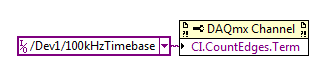
In DAQmx you can achieve the same result by setting the terminal entrance for a task of edge to the time base County internal 100 kHz:
The 100 kHz Timebase is considered to be a "Advanced terminal" (don't get started me on the topic) so see in the dropdown menu, you must right-click on the control / constant and select the appropriate name of I/O filtering option.
Best regards
-
Routing of signals DAQmxCfgSampClkTiming
Is it possible that I can find what type of routing not DAQmxCfgSampClkTiming between two boards?
I use the ANSI C interface and analog output PCI-6733 (series AO) two boards connected with a RTSI cable. I tried following suggestions on the manual on the device making slave have the same clock from 20MHzTimebase and I kept getting error "there are no more resources for this course" type of messages.
It was not up to what I've avoided any type of signal explicit routing and just used "/ Dev1/ao/SampleClock" as the clock source sample on the slave (Dev2) device that the analog compiling output began to work (after the reset of the device, BTW). I'm just curious to see what kind of signal routing DAQmxCfgSampClkTiming has put in place under the hood.
The test program seems to work well and signals in sync, but I want to make sure I am configuring correctly.
The DAQmxGetExported... Features of the term show nothing since I imagine that it is all related to the task rather than the immediate delivery. The DAQmxGetAO... functions do not seem anything to know the routes.
Thank you
One last thing: PCI-6733 uses the chip of TCC, which is what use the E series devices.
-
Analog output with counter Falling Edge
Hi all
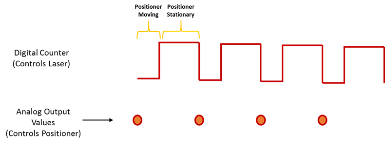
Here's the iamge which describes what wishes to accomplish. I would like to trigger that the AO output with the edge of the fall of the meter.
I have set the clock for my AO as the counter.
The analogue output should be raised whenever the Digital signal meter falls
SAMPLE_SIZE = 80
SAMPLING_RATE = 40 #Samples are written every 25 milliseconds
TIME = float ((SAMPLE_SIZE) / (SAMPLING_RATE))CREATE TASKS
CREATE CHANNELS OF AO
CONFIGURE THE TIMING CHANNELS
DAQmxCfgSampClkTiming (taskHandleAO, "PFI12", SAMPLING_RATE, DAQmx_Val_Falling, DAQmx_Val_FiniteSamps, SAMPLE_SIZE)CREATE TASKS
CREATE A CHAIN COUNTER
# Time high-low + time equals 25 milliseconds and is proportional to the frequency of sampling
DAQmxCreateCOPulseChanTime(taskHandleD,"DAQ/ctr0","",DAQmx_Val_Seconds,DAQmx_Val_Low,0.00,0.005,0.020)# The values of voltage DAQmx writing
DAQmxWriteAnalogF64(taskHandleAO,SAMPLE_SIZE,0,10.0,DAQmx_Val_GroupByChannel,Voltage,None,None)# DAQmx AO task start
DAQmxStartTask (taskHandleAO)# Counter DAQmx Start task
DAQmxStartTask (taskHandleD)#TIME is equal to the total time for the writing samples
DAQmxWaitUntilTaskDone (taskHandleD, 2 * TIMES)I get an error every time that I run the task:
DAQError: Over Acquisition or generation has been stopped until the required number of samples were acquired or generated.

 function DAQmxStopTask
That's because my AO task is stopped for some reason any.
Is there an obvious problem with the code. Can it be structured differently?
best regards,
Ravi
I do all my programming in LabVIEW, so I'm pretty limited to help with programming syntax text. That being said, here's what I * think * I see:
Your AO task issues a call to DAQmxCfgSampClkTiming, but is not your task of counter. This probably leaves you with a meter spot which creates only a single impulse, which causes only a single AO D/A conversion. In LabVIEW when I need a pulse train, I would call a similar function of the synchronization with the clock mode is defined as 'implied '.
Hope this helps you get started, I don't know enough to give you the specific syntax in the text.
-Kevin P
-
How to generate a pulse signal?
Hello
I'm relatively new to LabVIEW and I need to generate an impulse (Dirac function) in the motor continuous. At the same time, I need to be able to change the pulse width.
I am currently using LabVIEW 7.1.
Hey,.
With your E-Series cards, you can counter to generate impulses for the user.
The best way to find examples using the Finder example under the Help menu of LabVIEW. Simply navigate to the e/s material > DAQmx > Counter > generate signals or search for pulse generation.
-
Airport express to extend my wifi signal
I bought and set up the Airport express to extend a wifi signal in my house. I do not have an airport extreme as a base station - I thought I could use the express to extend the signal from my router/modem from verizon. Is this possible?
Turned it "on" now, I don't see the express network as an option in my combo network - so assuming that it will seek to expand, what's the problem with it only shows not not in the drop-down list?
The AirPort Express only wireless may extend over a network that is provided by another router from Apple. As such, it cannot extend wireless signal router left 3rd.
Another way of saying the same thing, it's that if you want to extend wireless network using a router from Apple, you will need two routers Apple.
If you can connect the AirPort Express Terminal to your main router using a wired Ethernet cable connection, permanent, then the Express can be configured to provide additional coverage of wireless signal in this way.
-
Helps the acquisition of photon counter data using LabView 12
Hey all,.
Student graduate Chemistry here new to LabView and are looking for some help moving in the right direction. I'm looking for help with connecting my meter to 12 LabView for data acquisition of trace-fluorescence photon PerkinElmer SPCM-AQR-14 (now owned by Excelitas Technologies). I just want to be able to acquire number of photon counts vs. time. Currently, I installed a PCI-6601 and use a BNC-2121 to connect the BNC of the sensor output. The detector has a pulse output digital TTL with 30 ns pulse width, and by contacting technical support on this issue, I was told that this pulse width was too short to always detected by the 6601, but can still go ahead and give it a try. Basically, if everyone is familiar with how to start with this configuration, ANY help would be greatly appreciated. As I said I'm all new to LabView and am currently spend all my spare time reading manuals and help files.
Please let me know if you need any kind of information to make me understand what I'm doing.
I would say something like this:
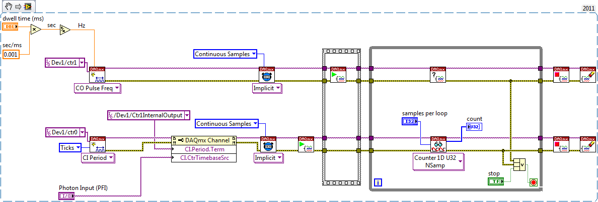
A measurement period the registry account out of the entrance of the samples as well as gives the meter. You will basically measure the 'period' of your sample clock fixed regarding ticks of the external photon signal.
According to the downtime, you may need to re-read several samples per loop so that the software can keep up with the incoming data. Also, the first sample is not useful because it represents the County between the software from the task of entry of the meter and the first clock signal - you should disregard/erase the first sample (or if you want you can set up a trigger to begin arms).
To do the same thing by using an edge County task would require using both the sample clock AND a counter reset signal - this not is not supported on 6601/6602 (even if it would be possible to set it up that way on a device of STC - 3 as a series of X).
Best regards
-
output signals of the rectangle a PEAK sine wave conversion
Hello
I have a question on the treatment of a PIC16F84 output signals. It seems that the simulation of Multisim does not work properly - but before I blame Multisim, I ask the community NOR or software engineers or a solution. Because I'm German, you are invited to continue this thread in German if it is allowed by the rules of the forum. If you need additional information to analyze my problem, I'll be happy to provide.
The circuit itself has to convert "composition by pulse" signals "tone" (DTMF tones). So you can get old, classic phones work on new devices that do not support the "composition of pulse" more.
The circuit is powered by the analog telephone line current loop line. The PIC is provided by a rudimentary voltage regulation and count pulse signals (voltage failures / power interruption on the telephone line). After that the captain means the series of impulses in their equal number (e.g. 3 pulses = number 3). The captain gives finally two signals with different frequencies to generate a DTMF tone (e.g. number 3 here is 697 and 1477Hz). As you can see in my PDF file attached, it works very well.
Now I have to convert the rectangle wave given by the captain to an at least similar to a sine wave form - otherwise the device that receives the DTMF tones won't understand them.
So I connected a low-pass filter at the output of the PIC. Now, expect the rectangle signal to be smooth in a way as the 'e-function' will (loading / discharging a capacitor through a resistor). But the results are very far from that - as you can see I have very strange curves.
When I implemented a frequency generator with the same output signal as the PEAK and the low pass filter even I get curves as expected.
So we can say that the output of the PIC works like a frequency generator in my circuit. But why does the filter not behave as it should?
I've tried a lot of different values for the parameters of my RC-filter and simulation - this does not solve the problem.
It would be nice if someone has any idea how to solve this problem.
Thank you.
The output impedance of the PEAK may be too high. May be that my car 50 output? Try scaling of impedance of the filter. Do the 10000 ohms resistance and capacitor 10 nF.
Lynn
-
Reduce the traces of routing between vias
With the help of Ultiboard and I'm curious to know if there is a setting in the motorway use, to reduce trace a path to go between vias in a PLUNGE? Or is redraw manually the copper trace the best method? See attached file...
TKS, Terry
TCjr,
Is there a reason that you don't want the tracks to go under the DIP?
(a) If you need create a specialized for certain signals routing path (as non-DIP), I recommend that send you these tracks manually first after the placement of the part.
(b) you can also place a narrow rectangular restricted area (and the automatic router must comply with the permitted/prohibited gave you) [in Ultiboard menu, place-> Keep-in/Kee-out area]. Keep out of the area by default prevents any trace routing through a particular area. If you don't want to keep everything out, first specify you a group net and then adjust the properties of the area to make the Dungeon to be applied to the net group only.
So it is possible, but only a few traces, it may be too much for what you do.
Kind regards
Pat Noonan
National Instruments
Maybe you are looking for
-
Cannot install Microsoft Silverlight
I try and intsaller microsoft silver light, but when I press on install I get a window that says "cannot install silverlight. another product is already installed. »But I don't know what else could settle. How would know that?
-
How can I keep my clock and icons when I go from desktop to a Web page?
Original title: XP Home Edition SP3. The clock and icons displayed in my taskbar, when I'm at the top of the desktop, do not remain when I go on a web page. Only the zoom feature is displayed. How can I keep my clock and icons when I go from desk top
-
I have an Advent Roma laptop and I know he has a webcam but I can't find a program here that will allow me to open it! can anyone help? There was also a little blue light next to the camera, which turned red and I did not Kow why?
-
Diff in regulars WAP vs LWAPs...
What is the difference between Pat and Pat light? I installed the 1100 (I think 1121) series about two years (relatively small deployments
-
BlackBerry Smartphones is frozen on the loading screen
Hi all Please help me for the below raised concerns (1) having the blackberry bold 9900 that freezes several times. He stuck where I worked to get resolved from this question in general I removed the battery from the handset. (2) but now after placin